10. Advanced DSL Customization
Introduction
You can design a good range of graphical languages just by editing the DSL definition. As we’ve seen in previous chapters, you can go beyond that, writing code to define validation checks (Chapter 7), to generate material from your users’ models (Chapter 8), and to customize the fine detail of the language features (Chapters 3–5). These extra facilities can be picked up progressively—the gradual steps upward that allow you broader and broader scope, as we illustrated in Chapter 1.
This chapter brings together the level of customization that involves writing code. Many of the topics have been touched on in earlier chapters, but here our intention is to go into customization techniques in more detail.
Tools for Customization
There are a number of basic mechanisms we use to enable us to integrate custom and generated code.
Partial Classes
Partial classes are the feature of .NET languages that allows the methods of one class to be compiled from several different files. All the generated classes are partial, allowing you not only to add methods of your own to a class in a separate file, but also to add overrides of methods defined in the framework base classes. Never change the content of the generated code—add material in separate files.
You can override and add methods to the generated code in your partial class. But if you add a private variable in a partial class, it won’t be kept in the store, and so (a) events and rules can’t be used to observe it, (b) any undo that the user performs won’t apply to it, and (c) it won’t be persisted and reloaded when the user saves the model. Generally, therefore, you should not declare member variables in custom code (even if you don’t need them to be persisted); declare properties in the DSL definition.
Double Derived—The Generation Gap
If you look at the generated code, for example, for any shape in DslGeneratedCodeShapes.cs, you’ll see that there are a variety of methods that it might be interesting to modify such as HasBackgroundGradient(), which always returns a fixed value (depending on how you have set the FillGradient domain property of the shape in the DSL definition). But perhaps you would like to make it variable at runtime so that the existence of the gradient can give some indication of state, and so you would like to override the method. Unfortunately, that is not how partial classes work; your custom code is in the same class as the generated material.
The solution is to select the domain class, relationship, or shape in the DSL definition and set to true the “Generates Double Derived” flag in the properties window. Now when you regenerate the code (by clicking “Transform All Templates” in the header of the solution explorer), the generator creates two classes, one derived from the other. All the generated methods and properties are placed into the base class, leaving only constructors in the derived class. It is always the derived class that is instantiated. In your custom code, you can now override any methods defined (or overridden) by the generated code (Figure 10-1).
Figure 10-1. Double derived classes

This is a use of the “Generation Gap” design pattern described by John Vlissides (in his book Pattern Hatching [Addison-Wesley, 1998]). It is an important technique wherever code is generated, enabling you to preserve the generated material and regenerate it when required without losing your customizations.
Double derived is useful for diagrams, shapes, and connectors. It is less useful for the generated code of domain classes and relationships because they just contain accessors for properties and relationships.
Some classes not directly defined in the DSL definition, such as Toolbox-Helper, are double derived by default.
Custom Constructors
Double derivation doesn’t work for constructors—the constructors have to be in the class they’re constructing, of course. If you want to override a constructor, therefore, you need to tell the generators not to create one. To do this, set the flag “Has Custom Constructor” in the domain class properties. The resulting generated code will not compile until you provide the constructor.
Customization Switches
Customization switches are Boolean properties in the DSL definition that cause the generated code to invoke a method that must be supplied by you. For example, if you set “Is Custom” in a connection builder, the solution will not build until you have supplied the missing code, in a partial class. Comments near the resulting errors in the generated code give brief guidance on what you need to provide.
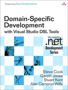
Table 10-1 lists the most commonly used customization switches.
Table 10-1. Customization Switches

Custom Overrides
A great many methods can be overridden to change the behavior of the designer, especially in shape, connector, and diagram classes. The complete set can be seen by writing a partial class and typing “override”—the Visual Studio IntelliSense system will prompt you with the possibilities.
Some useful overrides are listed in Table 10-2.

Responding to Changes
Much of the custom code you need to write within a designer is about responding to changes initiated by the user, or in some cases preventing certain changes. This section brings together all the techniques for doing that. Some of them we have discussed before, but here we try to compare and contrast so that you can see which technique to apply.
As a rough guide, consider the techniques in the order of presentation here.
Property Handlers “On Value Changed/Changing”
Each domain class has an internal handler class for each property. This has methods you can override: in particular, OnValueChanging() and OnValueChanged(), called immediately before and immediately after the changes.
For example, if a domain class IssueProject has a string domain property Sort, we can add a partial class like this:
public partial class IssueProject
{
internal sealed partial class SortPropertyHandler
{
protected override void OnValueChanged(State element,
string oldValue, string newValue)
{
if (!this.Store.InUndoRedoOrRollback)
{
// propagate in-Store changes here...
}
// propagate external changes here...
// And always call the base method!
base.OnValueChanged(element, oldValue, newValue);
}
}
}
The handlers are only called if the new and old values are not the same; they don’t get called just because an assignment has happened.
Use OnValueChanged to propagate changes either inside or outside the store.
One use of OnValueChanging is to throw an exception if you don’t like the value that is about to be set.
These handlers are not available for built-in properties such as the bounds of a shape.
Undo, Redo, and Property Handlers
If the user invokes “undo,” all of the changes made to the store in the most recent top-level transaction are undone. The undo mechanism essentially works by keeping a trail of previous values of every property, instance, link, and shape in the store. Undo replaces every value with its old one, while redo just winds the tape forward again.
This means that methods and rules that only propagate changes around the store should not operate when an undo or redo is happening. If a method’s job is to keep one store value in line with another, then it only needs to calculate a new value when we’re really going forward.
For this reason, the above code uses Store.InUndoRedoOrRollback to guard the part of the code that deals with in-store content, that is, anything that sets any domain property, or creates or deletes an instance of a domain class or relationship, or a shape, connector, or diagram.
However, let’s suppose that this domain property’s purpose is to be the proxy for some external state: a database entry, a piece of user interface, or even a chunk of hardware. In that case, the handler should certainly keep the external state in step with undos and redos, and that part of its code would be outside the guard.
Calculated Domain Properties
A calculated domain property is not stored but always computed using a getter you supply.
Calculated properties are good for any case where the property should be a determined function of either external state, or other parts of the model—for example, a sum of other values, a count of relationships, or a composition of other strings.
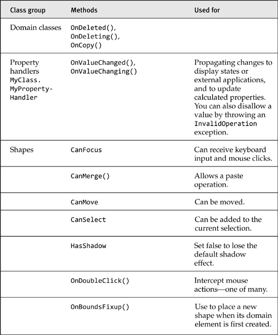
There is an example of a calculated property in the Class Diagrams sample that can be found in the Visual Studio SDK Samples. Each Model-Attribute displayed in a ModelClass has two domain properties called name and type, which the user can see and alter in the properties window in the usual way. But on the diagram, each ModelAttribute’s name and type appear in a single line: “name : Type”. This is useful because each model attribute appears as one line of a compartment shape (Figure 10-2).
Figure 10-2. Two property values displayed on one line in a compartment shape
To get this effect, we create a domain property called NameAndType in the ModelAttribute domain class, and set its “Kind” to Calculated in the properties window. “Transform All Templates” and an attempt at building produce the error message that we have not defined a method in the Model-Attribute class, and following the error takes us to a helpful comment in the generated code that tells us what’s expected: in this case, a getter method for NameAndType.
The expected method for a calculated domain property is always called GetXXXValue(), where XXX is the name of the domain property. In a separate custom code file, we provide the required code. It just combines the values from the two other domain properties:
public partial class ModelAttribute
{
public string GetNameAndTypeValue()
{
return this.Name.Trim() + " : " + this.Type.Trim();
}
}
To avoid confusing the user, we set the “Is Browsable” flag of this domain property to false, so that it does not appear in the properties window at runtime. (You could alternatively set “Is UI Read Only” to true, which allows the user to see it in the properties window without modifying it there.)
You can use any source data for the calculation—they don’t have to be in the store. For example, you might use the value to determine the orientation of an image, or perhaps to set the content of a file.
Custom Storage Domain Properties
A CustomStorage domain property is one where you provide both setter and getter. You save the value however you like—for example, in the state of some external application or just by setting the values of other properties in the store.
In the Name and Type example, rather than insist that values be entered through separate lines in the properties window, we can let the user set both name and type properties by typing into the display field, separating the name and type with a colon (“:”).
Set the NameAndType property’s “Kind” to CustomStorage, transform, and rebuild in the usual way. The build error tells us we need another method:
public partial class ModelAttribute
{
public void SetNameAndTypeValue(string newValue)
{
if (!this.Store.InUndoRedoOrRollback)
{
// in-Store changes
string[] separated = newValue.Split(new char[] { ':' });
if (separated.Length > 0) this.Name = separated[0].Trim();
if (separated.Length > 1) this.Type = separated[1].Trim();
}
// Handle here any propagation outside the Store.
}
}
Notice that this method guards changes it makes within the store with InUndoRedoOrRollback, in the same way as OnValueChanged(); and if there are any changes to be made outside the store, they should happen anyway.
If you really want to ensure that your custom storage domain property works just like a real one, then you should
• Do nothing if the old and new values are equal.
• Call ValueChanging() and ValueChanged() before and after your update; these in turn call OnValueChanging/ed() and ensure that any rules defined on the property work properly.
The extended result looks like this:
public partial class ModelAttribute
{
public void SetNameAndTypeValue(string newValue)
{
string oldValue = this.GetNameAndTypeValue();
if (oldValue != newValue)
{
ValueChanging(this, newValue, oldValue);
if (!this.Store.InUndoRedoOrRollback)
{
// in-Store changes
string[] separated = newValue.Split(new char[] { ':' });
if (separated.Length > 0) this.Name = separated[0].Trim();
if (separated.Length > 1) this.Type = separated[1].Trim();
}
// Handle here any propagation outside the Store.
// ...
ValueChanged(this, newValue, oldValue);
}
}
}
Tip: Calculated properties, Custom Storage, and value handlers
Use Calculated properties where you want a value to depend completely on others, and want it to be read-only. Use Custom Storage properties when you also want to write back to the places from which the value is derived. If those other values can’t represent all of its state, use an ordinary property but propagate its value with OnValueChanged ().
Notify Value Change
If you tried the Calculated Value example, you may have noticed that when you change, say, the Type property, the display of the calculated NameAndType does not immediately change. You have to reselect the diagram or cause a redisplay in some other way to see the change.
By themselves, custom and calculated values don’t automatically propagate changes to their observers. They will recalculate the value when asked, but unlike ordinary domain properties, have no inbuilt mechanism for telling interested parties when the calculated value might have changed. We have to do this for them, by observing each of the source values in some way—for example, by overriding a property handler—and calling Notify-ValueChange() on the calculated or custom domain property. That call will propagate changes to observers by firing rules and events just as a change in a normal property does.
public partial class ModelAttribute
{
internal sealed partial class TypePropertyHandler
{
protected override void OnValueChanged(ModelAttribute element,
string oldValue, string newValue)
{
base.OnValueChanged(element, oldValue, newValue);
element.Store.DomainDataDirectory.
GetDomainProperty(ModelAttribute.NameAndTypeDomainPropertyId)
.NotifyValueChange(element);
}
}
}
Notice the method is actually on the DomainPropertyInfo class, whose instance represents the definition of the NameAndType domain property within the ModelAttribute class. (This is one of the metadata classes from which you can get information at runtime about the DSL definition.)
Propagating Change from Model to Shape: OnAssociatedPropertyChanged
As we know from Chapter 4, the shape map is the principal method of defining how model elements and links are presented using shapes and connectors. The visibility of the shapes’ decorators and the text presented in the shapes can be controlled by the domain properties of the presented model elements.
The mechanism we look at here provides a complementary and more customizable method that allows change to propagate along the same conduit: the PresentationViewsSubject relationship between model elements and their presentation elements.
As an example, consider the class diagrams standard template that comes with the DSL Tools. Running it, you see that it allows you to draw classes that can be interconnected by several different kinds of association. Unfortunately, once you have created a particular sort of association, you cannot change it to any other, and the several different sorts make a long list in the toolbox (Figure 10-3).
Figure 10-3. Standard Class Diagrams template has several separate types of association.

We can make a substantial improvement on this. (And there is an implementation of this solution in the class diagrams sample that comes with the Visual Studio SDK—look in the sample browser.)
Let’s just have a single type of Association (a relationship between the model classes), and let’s give it an enumerated property Sort. We want the user to be able to change the sort of an existing association simply by selecting it and changing its “Sort” in the properties window. In response, the ends of the connector should change to show various combinations of diamonds, arrowheads, and plain ends.
First, features such as connector ends, line thicknesses, colors, and so on are not governed by the shape maps, so we need to use custom code to change them.
For OnAssociatedPropertyChanged() to work, we must first set it up by calling a static method of the connector. We only need to do this once for the class—it isn’t necessary to set up an observer relationship separately for each instance. We set it up like this:
public partial class AssociationConnector
{
protected override void InitializeResources (StyleSet classStyleSet)
{
base.InitializeResources(classStyleSet); // don't forget!
AssociationConnector.AssociateValueWith(this.Store,
Association.SortDomainPropertyId);
}
Tip: Override InitializeResources to set up per-class relationships involving shapes or connectors
Even though this is an instance method, it is called once for each shape or connector class when the package is loaded. It’s better to perform setups here than in a class initializer, because at this point all the required initializations will have been done.
In some cases it is necessary to set the “Generates Double Derived” flag for the shape or connector in the DSL definition.
In this DSL definition, AssociationConnector is the connector that will present Association relationships on the screen. The argument Association.SortDomainPropertyId identifies the Sort domain property of the relationship to which the connector is mapped. Each property has a XXXDomainPropertyId.
Once this setup has been performed, OnAssociatedPropertyChanged() will be called whenever this domain property’s value changes. We write it in the same class:
protected override void OnAssociatedPropertyChanged
(PropertyChangedEventArgs e)
{
// Called for a change in any property, so we must discriminate:
if ("Sort".Equals(e.PropertyName))
{
// OK; we know the type of domain property "Sort" from DSL Defn:
switch ((AssociationSort)e.NewValue)
{
// Set the arrowheads depending on the sort of association:
case AssociationSort.Aggregation:
this.DecoratorTo = null;
this.DecoratorFrom = LinkDecorator.DecoratorEmptyDiamond;
break;
// and so on for other values and other properties...
}
}
base.OnAssociatedPropertyChanged(e);
}
This method will be called on an instance of the connector whenever any associated property changes on the mapped domain relationship instance. It is essential to begin by checking which property has changed, because the generated code may have registered the class to observe several other properties. The event arguments contain the name of the changed property and its old and new values. The old and new values will always be of the appropriate type for the property (possibly including null).
The arrowheads, colors, line thickness, visibility, and other visual properties of a shape or connector are not domain properties, persisted in the store—although the shapes and connectors themselves are. These properties should therefore be handled as we’ve described for external state, so there is no check to see whether we are InUndoRedoOrRollback. (It is possible to define domain properties on shapes, and you could use OnAssociatedPropertyChanged() to update them from the model element properties. In that case, you would avoid updating them in an Undo.)
Always call the overridden method in base; in this case, we do so at the end, because it will take care of redisplaying the connector.
Tip: Use OnAssociatedPropertyChanged to link shape features to domain properties
This is the easiest way to make the color, line thickness, and other features of a shape depend on domain properties.
Why don’t we use some other method to perform this function? For example, could we define an OnValueChanged() in the Sort domain property, and make that update the arrowheads? Well, yes, but (a) it would be necessary to navigate explicitly the PresentationViewsSubject link between the model element and the connector, (b) to future-proof that, we should allow for the possibility of different views on the same model, and (c) putting the display logic in the main part of the model doesn’t feel like good separation of concerns. The OnAssociatedPropertyChanged() method provides you with a convenient way to add relationships between presentation and model, augmenting the basic facilities of the shape maps.
Rules
Rules are the most general purpose mechanism for propagating and responding to change within the store. Rules are triggered by changes in the store such as property value changes, or the creation or deletion of an object or link, shape, or connector.
In the usual case, the rule executes during the Commit() operation of the outermost transaction in which the triggering change occurred. A rule can trigger further firings, which are added to the end of the queue. The transaction is completed when the rule firing queue is empty. It is of course possible for badly organized rules to cause a transaction never to complete, until the firing queue runs out of space.
Tip: Consider other mechanisms before rules
Because rules can execute in a difficult-to-control order, a large set of rules can be difficult to debug. So although rules are a powerful and general mechanism, it’s good to look first for other ways of achieving the result you want.
Here is the code of a rule. This rule responds to the change of any shape’s absolute bounds (that is, if it moves or changes shape).
[RuleOn(typeof(NodeShape), FireTime = TimeToFire.TopLevelCommit)]
public sealed class ContainerShapeChangesRule : ChangeRule
{
public override void ElementPropertyChanged
(ElementPropertyChangedEventArgs e)
{
NodeShape stateShape = e.ModelElement as NodeShape;
if (stateShape == null) return;
if (stateShape.Store.TransactionManager.
CurrentTransaction.IsSerializing)) return;
if (e.DomainProperty.Id == NodeShape.AbsoluteBoundsDomainPropertyId)
{
RectangleD oldBounds = (RectangleD)e.OldValue;
RectangleD newBounds = stateShape.AbsoluteBoundingBox;
HandleAbsoluteBoundsChange(stateShape, oldBounds, newBounds);
} }
• The RuleOn attribute marks this class as a rule.
• The rule class can be called anything you like, but must inherit from one of a fixed set of abstract rules.
• The rule is defined on a class (NodeShape, in this case); it does not have to be separately registered for each instance.
• The code of the rule is entirely separate from the code of the class it observes.
The RuleOn Attribute
[RuleOn(typeof(NodeShape), FireTime = TimeToFire.TopLevelCommit)]
The attribute specifies the observed class, which may be any domain class, relationship, shape, connector, or diagram. You cannot specify that a rule observes a particular property of a class, nor that it observes specific instances. You must specify the class to which the property you are interested in belongs. In this case, we specify NodeShape so that we can look at the AbsoluteBounds properties of the shapes.
NodeShape is the common base class of all shapes. To catch all connectors, use BinaryLinkShape; all connectors or shapes, ShapeElement; all relationships, ElementLink. ModelElement is the superclass of everything.
You can apply as many rules as you like to the same class. Changes in any instance of the class (and its subclasses) will trigger all the applied rules.
TopLevelCommit is the usual FireTime, but you can also specify Local-Commit, which means that the rule executes at the end of the innermost transaction; or you can specify InLine, which means that the rule executes as soon as possible after the triggering change.
You can also set a Priority integer. The problem with using priorities is that you pretty soon get to devising some big table of all the relative priorities of your rules and start depending on them firing in that order, with one rule depending on another having set something up. Pretty soon after that, you’re into rule spaghetti, finding it impossible to debug heaps of rules that fire in the wrong order. So on the whole, it’s easier to leave the priority at the default and write your rules not to assume any particular order of execution.
You can set InitiallyDisabled = true in the RuleOn attribute, and rules can be turned on and off using the store’s RuleManager. In Chapter 7, we saw an example where the rule was turned off until the model had loaded.
store.RuleManager.EnableRule(typeof(ContainerShapeChangesRule));
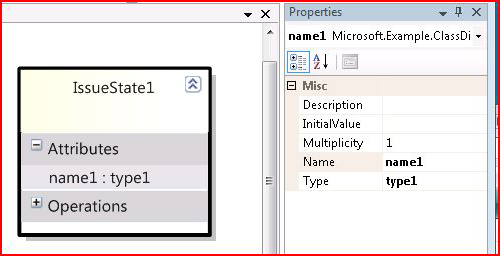
Rule Types
Each rule must be a subclass of one of a fixed set of base classes. These provide the means to observe different categories of events. Rule base classes are listed in Table 10-3.
Rule Body
The name of the method you override and its parameter type vary between rule types. Type “override” and let IntelliSense do the rest! For a ChangeRule, you get the model element that has changed, the Id of the property that has changed, together with its old and new values.
Remember to test the domain property Id, because the method will be called for every property of the class. Every domain property has a domain property Id, that is a static constant of its declaring class. In addition to the domain properties you have declared in your DSL, there is a small selection of predefined properties on the base classes. NodeShape has two such properties—AbsoluteBounds and IsExpanded—which in the method arguments are identified by their Ids AbsoluteBoundsDomainPropertyId and IsExpandedDomainPropertyId.
This example responds to changes in the location of a shape.
public override void ElementPropertyChanged
(ElementPropertyChangedEventArgs e)
{
NodeShape stateShape = e.ModelElement as NodeShape;
if (stateShape == null) return;
if (stateShape.Store.TransactionManager.
CurrentTransaction.IsSerializing)) return;
if (e.DomainProperty.Id == NodeShape.AbsoluteBoundsDomainPropertyId)
{
RectangleD oldBounds = (RectangleD)e.OldValue;
RectangleD newBounds = stateShape.AbsoluteBoundingBox;
HandleBoundsChange(stateShape, oldBounds, newBounds);
} }
Rules and Calculated and Custom Storage Domain Properties
Store rules and events cannot be set on calculated or custom storage properties. Instead, you need to set rules on the sources of the values.
Rules and Transactions
Every rule fires within the transaction that triggered it. This means that from the user’s point of view, the effects of the rules are all part of the same change as their trigger. In this example, moving a shape moves all those contained within it. If the user clicks the “Undo” button, all the shapes move back to their original places.
An alternative approach would have been to use the OnAbsoluteBounds-Changed event. This works after the original transaction has completed—to make any changes to the store (such as shape locations), you have to open another transaction. This means that if the user then clicks “Undo,” the contained shapes would be shifted back but the original move of the container shape would not. If this is the effect you want, don’t use a rule.
Rules are not called as a result of changes in an undo or redo, or when a transaction is being rolled back. The assumption is that all the changes you make in a rule are to other values within the store; the undo manager will reset these to their former values, so there should be no need to call any rules.
For this reason, you should not use rules to change values that are outside the store. This would be other values in your application such as file contents or some of the purely graphical properties of the shapes such as color or line thickness.
Transaction Context
Rules are a very powerful facility, but one of the difficulties working with rules is in passing information between rules, and between the triggering events and the rules. For this reason, each transaction carries a general dictionary to which you can attach information. Transactions can be nested, so it’s best always to make sure you’ve got hold of the outer one:
stateShape.Store.TransactionManager.
CurrentTransaction.TopLevelTransaction.Context.ContextInfo
You can get to the transaction from any domain class instance through the store. You may need to check that there is a current transaction first! The ContextInfo is a Dictionary <object, object>. In simpler cases, you might just use the top-level transaction name to check the reason your rule has been triggered.
Registering a Rule
To ensure a rule runs, you need to register it with your domain model class. (Check in the generated DomainModel.cs for its name.)
public partial class StateChartsDomainModel
{
protected override Type[] GetCustomDomainModelTypes()
{
return new System.Type[] { typeof(ContainerShapeChangesRule) };
}
}
If you have a lot of rules, you can cook up a reflexive mechanism that returns all the rule types so that you don’t have to add them all to this array manually.
Store Events
Store events are similar to rules, but are called after the completion of the originating transaction and are called on any subsequent undo or redo.
Tip
Unlike rules, store events are good for keeping non-store values in line with the objects and properties in the store
Like rules, store events are defined on a per-class basis. You don’t have to register the observer with each object it is observing, and you don’t have to modify the class you are observing.
In this example, we set up a change handler to deal with changes in any domain properties of the State domain class. Notice that we put this in the DocData class, which manages the loading of the document.
public partial class DocData
{
// Called once on loading.
protected override void OnDocumentLoaded(EventArgs e)
{
base.OnDocumentLoaded(e);
Store store = this.Store;
DomainClassInfo observedClassInfo =
this.Store.DomainDataDirectory.FindDomainClass(typeof(State));
this.Store.EventManagerDirectory.ElementPropertyChanged.Add
(observedClassInfo,
new EventHandler<ElementPropertyChangedEventArgs>
(StateChangeHandler));
}
private static void StateChangeHandler
(object sender, ElementPropertyChangedEventArgs e)
{
State changedElement = e.ModelElement as State;
if (e.DomainProperty.Id == State.NameDomainPropertyId)
{
// Do stuff to things outside store.
}
} }
Substitute for ElementPropertyChanged and ElementPropertyChanged-EventArgs to listen for different events. The flavors of events that can be handled are:
• ElementAdded
• ElementDeleted
• ElementMoved
• ElementPropertyChanged
• RolePlayerChanged
• RolePlayerOrderChanged
• ElementEventsBegun
• ElementEventsEnded
• TransactionBegun
• TransactionCommitted
• TransactionRolledBack
The corresponding argument types are called “<event name>EventArgs.”
Generally, if you want to respond to the same event with some work both on external and on in-store elements and their properties, then it’s best to set up a separate rule for the in-store material. However, if you do want to work on the store elements from the event, bear in mind that you must create a transaction to do it in, and you should not perform those actions if the event is called as a result of an undo or redo:
// Do things in Store, but not in Undo
if (!changedElement.Store.InUndoRedoOrRollback)
{
using (Transaction t =
this.Store.TransactionManager.BeginTransaction("event x"))
{
// Do things here to domain elements and shapes.
// ...
t.Commit();
} }
.NET Event Handlers
There are a number of .NET events that you can use, particularly in the shape classes. They mostly report user interface events like mouse and keyboard actions. They all happen outside any transaction, so if you want to use them to change a property, element, or link, you need to open a transaction. This kind of event will not normally be called on undo, since it originates outside the store, so we don’t need to guard against UndoRedoOrRollback.
public partial class StateShape
{
protected override void InitializeInstanceResources()
{
base.InitializeInstanceResources();
this.DoubleClick += StateShape_DoubleClick;
}
void StateShape_DoubleClick(object sender, DiagramPointEventArgs e)
{
StateShape shape = sender as StateShape;
// Do things here to non-store objects, outside transaction.
// ...
using (Transaction t =
this.Store.TransactionManager.BeginTransaction("double click"))
{
// Do things here to domain elements and shapes.
// ...
t.Commit();
}
}
}
Although in this example, the listener is the object itself, an advantage of an event handler is that you can set it up from any object to listen to any other object without changing the observed object’s code. However, the event listener has to be set up separately for each instance.
Events are available on shapes, connectors, and diagrams for Absolute-BoundsChanged, Click, DoubleClick, KeyDown, KeyPress, KeyUp, MouseDown, MouseMove, MouseUp, and MouseWheel.
Event Overrides
A simpler approach in cases where the listening code can be in the subject class is to override the event-raising method. For each event, there is a corresponding On<event name> method. In addition, there are some others, including BoundsFixup, Begin/EndEdit, ChildConfigured/ing, ShapeInserted/Removed, and a variety of drag, mouse, keyboard, and painting events.
Always be sure to call the base method.
public override void OnDoubleClick(DiagramPointEventArgs e)
{
base.OnDoubleClick(e);
Diagram d = e.DiagramClientView.Diagram;
// respond to event ...
}
Bounds Rules
A bounds rule is used to constrain the location or dimensions of a shape in response to a user gesture. It is very specific to this function, providing feedback in the “rubber band” as the user drags a corner to alter the shape. (As such it is rather different from the other change propagation mechanisms in this section, but we include it here because if we didn’t, you might think some of the other types of rules look like a reasonable way to achieve the effect!)
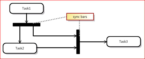
For example, in the Task Flow DSL, there is an object called “synchronization bar.” (It represents where a flow splits into concurrent threads or where they join again.) The shape is ideally a solid bar of fixed dimensions, but it can be used either horizontally or vertically (Figure 10-4).
Figure 10-4. Synchronization bars can be horizontal or vertical.
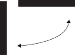
In the template that comes with the DSL Tools, the shape is represented by a rectangular geometry shape (with shadow and shading turned off). Unfortunately, the user can change the shape to any size or shape—we would prefer only to allow two alternatives, the horizontal and vertical. By adding a bounds rule, we can ensure that the user can only achieve two shapes (Figure 10-5).
Figure 10-5. This bounds rule constrains the shape to two alternatives.
A bounds rule is represented by a class. To attach it to a class, override the BoundsRules property of the Shape class.
public partial class SyncBarShape
{
/// <summary>
/// Provide a specialized rule that constrains the shape and/or
/// location of an element.
/// </summary>
public override BoundsRules BoundsRules
{
get
{
return new SyncBarBoundsRule();
}
}
}
The rule class itself has one method, GetCompliantBounds():
/// <summary>
/// Rule invoked when a shape changes its bounds.
/// Provides real-time mouse rubber-band feedback, so must work fast.
/// </summary>
public class SyncBarBoundsRule : BoundsRules
{
public override RectangleD GetCompliantBounds(ShapeElement shape,
RectangleD proposedBounds)
{
double thickness = 0.1;
if (proposedBounds.Height > proposedBounds.Width)
{
// There is a minimum width for a shape; the width will
// actually be set to the greater of thickness and that minimum.
return new RectangleD(proposedBounds.Location,
new SizeD(thickness, proposedBounds.Height));
}
else
{
// There is a minimum height for a shape; the height will
// actually be set to the greater of thickness and that minimum.
return new RectangleD(proposedBounds.Location,
new SizeD(proposedBounds.Width, thickness));
}
}
}
When you run the code, you’ll find that the shape is constrained while you drag the corners; it doesn’t go wherever you drag it and then snap to shape afterwards. The rule is being invoked repeatedly as you drag the corner. For this reason, it’s a good idea to make the code perform pretty snappily!
While this rule constrains the size or relative lengths of the shape, you could equally write a bounds rule that constrains the location of the shape. For example, you could anchor a shape to part of a container or neighbor. In the case where the user drags the whole shape, the rule is only executed once, when they let go.
Notice that there are two distinct cases—either users move the whole shape, or they drag a corner or a side to alter the lengths of its boundaries. In the case of a whole-shape move, the bounds rule is invoked once, and the lengths of the sides will not have changed. In the case of a side-length adjustment, the bounds rule is invoked repeatedly, and the side lengths vary. Within the rule, you can work out which case is happening by comparing the old and new side lengths; but remember that, as with any values of double or float types, it can be unreliable to compare for equality without some rounding.
Bounds Rules on Ports
You can apply a bounds rule to a port, for example, to fix or constrain it to a particular location on the parent shape. Your rule overrides the normal port positioning constraints.
Notice the following:
• The property ParentShape navigates from the port shape to its parent. It may be null when the child shape is first created.
• The location of the port shape that you should return is relative to the location of the parent.
This also applies to other kinds of child shape, although you can’t create these without custom code in the present version of the DSL Tools. This example comes from the Components sample that comes with the DSL Tools:
public class InPortBoundsRules : BoundsRules
{
public override RectangleD GetCompliantBounds
(ShapeElement shape, RectangleD proposedBounds)
{
InPortShape portShape = shape as InPortShape;
ComponentShape parentShape =
portShape.ParentShape as ComponentShape;
// on initial creation, there is no parent shape
if (parentShape == null) return proposedBounds;
double x = Math.Min(
Math.Max(proposedBounds.Left, proposedBounds.Width * 0.5),
parentShape.AbsoluteBoundingBox.Width
- proposedBounds.Width * 1.5);
double y = parentShape.AbsoluteBoundingBox.Height
- proposedBounds.Height * 0.5;
return new RectangleD(x, y,
proposedBounds.Width, proposedBounds.Height);
}
}
Undoable Changes
You’ll be familiar with the way Microsoft Word adjusts your quotation marks or indenting as you type. Sometimes you really did want what you typed in the first place, so you can undo the (sometimes irritating!) adjustment. You may want to provide the same facility in your DSL. The user moves the shape; you shift it to an “approved” place; then the user may press Ctrl+Z to undo your adjustment—she really does want it where she put it, thank you.
To do this, override OnAbsoluteBoundsChanged in your Shape class. This method is called after the close of the transaction in which the user’s move happened. Therefore, you must make your adjustment inside a new transaction. This means that if the user calls undo afterwards, the first undo will apply only to your adjustment, and another will undo the original move.
public override void
OnAbsoluteBoundsChanged(AbsoluteBoundsChangedEventArgs e)
{
base.OnAbsoluteBoundsChanged(e);
// Decide whether to adjust
if (e.NewAbsoluteBounds.Height > e.OldAbsoluteBounds.Width)
{
// Now outside the original transaction; so open another.
using (Transaction t =
this.Store.TransactionManager.BeginTransaction
("adjust shape"))
{
// Make adjustment
// ...
t.Commit(); // Don't forget to commit
// - notice BoundsRules will be called again here
}
}
}
Summary of Change Propagation and Constraint Techniques
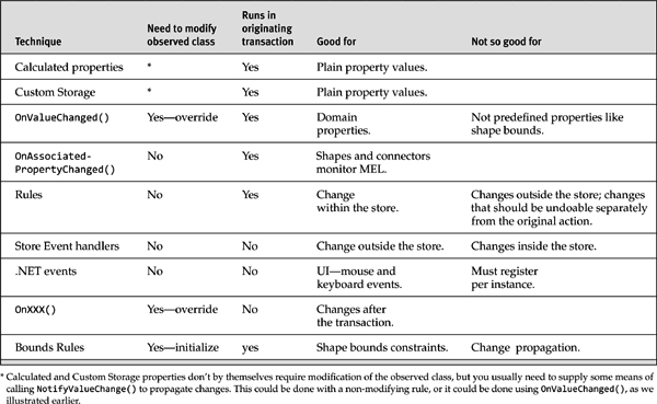
Table 10-4 summarizes the techniques we have discussed for propagating changes and applying hard constraints.
Table 10-4. Change Propagation and Constraint Techniques
The next few customizations aren’t limited to your DSL definition and its diagram; they’re more strongly tied to the way your DSL is integrated into the Visual Studio environment. To this end, it’s helpful before going further to have a better understanding of what a DSL actually is from the point of view of the IDE and its extensibility mechanisms.
DSL Shell Architecture
Visual Studio is a highly extensible tool platform. The product feels like a single integrated tool when you use it out of the box, but actually it’s based on a core IDE shell and a set of extensibility plug-ins called packages that provide most of the functionality, such as the C# code editor and project system, the Windows Forms GUI builder, and the RAD database tools.
A Visual Studio package is simply a DLL that contains classes that implement a well-defined set of interfaces to enable them to integrate into the IDE. Packages can be used to add or extend almost any kind of functionality within the IDE, such as new editors, programming languages, tool windows, debuggers, and so on. The Visual Studio SDK that the DSL Tools is contained in is primarily concerned with providing facilities to make this task easier. You can find much more information in the SDK’s included documentation and also online at the Visual Studio 2005 Extensibility Center at http://msdn2.microsoft.com/en-us/vstudio/aa700819.aspx.
The DSL Tools add a new editor for your DSL by creating a Visual Studio Package. You can find this in the DslPackage/GeneratedCode/Package.cs file of your DSL solution. We generally refer to the way the DSL is integrated into the IDE as the shell, because the IDE is providing an outer shell for your language. You’ll find the base classes for code in this area in the Microsoft.VisualStudio.Modeling.SDK.Shell.dll.
The key elements of a package declaration look like this:
[DefaultRegistryRoot("Software\Microsoft\VisualStudio\8.0")]
[PackageRegistration(RegisterUsing = RegistrationMethod.Assembly,
UseManagedResourcesOnly = true)]
[ProvideToolWindow(typeof(MyDSLExplorerToolWindow),
MultiInstances = false,
Style = VsDockStyle.Tabbed,
Orientation = ToolWindowOrientation.Right,
Window = "{3AE79031-E1BC-11D0-8F78-00A0C9110057}")]
[ProvideToolWindowVisibility(typeof(MyDSLExplorerToolWindow),
Constants.MyDSLEditorFactoryId)]
[ProvideEditorFactory(typeof(MyDSLEditorFactory), 103,
TrustLevel = __VSEDITORTRUSTLEVEL.ETL_AlwaysTrusted)]
[ProvideEditorExtension(typeof(MyDSLEditorFactory),
"." + Constants.DesignerFileExtension, 32)]
[RegisterAsDslToolsEditor]
[ComVisible(true)]
internal abstract partial class MyDSLPackageBase : ModelingPackage
{
protected override void Initialize()
{
base.Initialize();
// Register the editor factory used to create the DSL editor.
this.RegisterEditorFactory(new MyDSLEditorFactory(this));
// Create the command set that handles menu commands
// provided by this package.
MyDSLCommandSet commandSet = new MyDSLCommandSet(this);
commandSet.Initialize();
// Register the model explorer tool window for this DSL.
this.AddToolWindow(typeof(MyDSLExplorerToolWindow));
...
}
...
}
You can see that the package class has a lot of custom .NET attributes applied to it. The way Visual Studio is told about the existence and facilities of packages is primarily by creating a set of registry entries under the HKEY_LOCAL_MACHINESOFTWAREMicrosoftVisualStudio8.0 key. This activity is known as package registration. These attributes (derived from the base class RegistrationAttribute) provide a handy way of defining those registry entries in a relatively human-readable and easily maintainable fashion. They enable the DSL Tools to build infrastructure to extract the data and create the registry entries. This is done on the fly during a build in the IDE and also as part of creating a setup program for your DSL tool.
The package is the entry point into Visual Studio for your DSL and you can see from the preceding code that it has registry attributes declaring the existence of several other interesting items that are then created in the Initialize() method:
• EditorFactory—Creates instances of your DSL editor via the DocData and DocView classes
• CommandSet—Implements menu commands in your DSL
• ToolWindow—Adds extra non-editor windows (in this case, your DSL explorer)
Figure 10-6 shows how these pieces fit together.
Figure 10-6. Shell architecture of a typical DSL tool
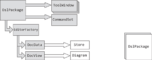
As we’ve seen, the package class registers the editor factory, tool windows, and command set. Visual Studio instantiates your package class as a singleton and also hooks it into the standard IServiceProvider mechanism to allow it to access other Visual Studio facilities (and provide its own services for use by other parts of Visual Studio, if desired). The package creates instances of the EditorFactory and CommandSet directly, but any tool windows are actually instantiated by Visual Studio; the package simply tells the system about their type.
The EditorFactory class is rather simple since it is, as its name implies, just a factory for your custom DSL editor. The editor itself comes in two parts, a DocData and a DocView.
The DocData class is your DSL’s backing store manager. It provides the entry points for loading and saving model and diagram files and manages the instance of the in-memory store in which your MELs live.
The DocView class represents the open window in Visual Studio, visualizing your diagram. It typically has a 1-1 relationship with the diagram instance within your store.
How to Add a Menu Command
The examples in this section are taken from the Class Diagrams sample that comes with the Visual Studio SDK (and can be found in the Samples Browser). This sample extends the plain Class Diagrams template solution in several ways.
Class diagrams have several sorts of association: aggregations, compositions, unidirectional, and bidirectional. In the template solution (that is, the one you get if you choose “Class Diagrams” in the wizard when you create a new DSL), each of these four sorts is separately implemented, with its own toolbox entry, its own domain relationship, and its own connector. The drawback of this arrangement is that if you want to change the sort of an association, all you can do is delete it and draw another one.
So in the Class Diagrams sample, there is a single class of association, but the sort is represented by an enumeration property. The user can change it either in the properties window, or by choosing the sort from a context menu. When the sort is changed, the line-ends (diamonds or arrows) change automatically.
The menu items appear when at least one association is selected (see Figure 10-7), and the change is applied to all associations selected.
Figure 10-7. Class diagrams example, with context menu on association

Add a Command Id for Each Command
In DslPackageCtcComponentsCommands.ctc, under the #include directives, add a line for each new command that looks like the following. The integer must be unique for commands in your DSL:
#define AssociationSortBidirectional 1
The Class Diagrams sample defines four commands in this way.
In the same file, add under “BUTTONS” an entry for each command like this:
guidCmdSet:AssociationSortBidirectional,
guidCmdSet:grpidContextMain,
0x0200,
OI_NOID,
BUTTON,
DIS_DEF,
"Set to Bidirectional" ; # Menu text
Notice that most of the content in this file (including the definitions of the constants) comes from the inclusion of GeneratedCodeGeneratedCmd.h and
<VS SDK>VisualStudioIntegrationCommonincDSLToolsCmdId.h.
Compare your entry with other lines in these files.
The first item on each line identifies the command. The prefix guidCmdSet qualifies it with a Guid unique to this DSL, and is defined in DslGenerated-CodeGeneratedCmd.h. The last item is the text that will appear on the menu.
More information about the Command Table Configuration (CTC) file (.ctc) can be found in the online MSDN Library (http://msdn.microsoft.com) under Development Tools and Languages>Visual Studio>Visual Studio SDK>Visual Studio Integration>Menu and Toolbar Commands. You can also install these help files locally with the Visual Studio SDK.
Increment Menu Resource Index
Whenever you change the CTC file, it is necessary to increment the second integer in this line in DslPackageGeneratedCodePackage.tt. (You do not need to do this when you are changing the code in the handlers of a command you have already defined.)
[VSShell::ProvideMenuResource(1000, /* Increment this: */ 5)]
This causes the Visual Studio menu cache to be reset when the package builds or installs.
As we mentioned earlier, “Provide...” attributes on the package are executed by regpkg during a build. The ProvideMenuResource attribute runs the compiled version of the CTC file. This places the commands into the Visual Studio command cache. The cache persists between runs of VS; this is because some packages require their commands to be visible even before the package is loaded so that a command can load and start its package. Because executing the cache update can be a lengthy operation, the ProvideMenuResource attribute doesn’t bother unless it notices a change of version. Running devenv/setup has the effect of rerunning all the command attributes for all the known packages.
Add Commands to Command Set
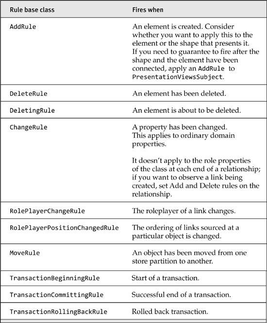
Add a new class file to CtcComponents. Ensure the namespace ends with DslPackage. (Delete the .CtcComponents that will have automatically been generated when you created the file.) Add using statements as shown here.
namespace Microsoft.Example.ClassDiagrams.DslPackage
{
using System;
using System.Collections.Generic;
using System.Text;
using System.ComponentModel.Design;
using Microsoft.VisualStudio.Modeling;
using Microsoft.VisualStudio.Modeling.Shell;
Create a partial class definition for YourLanguageCommandSet, marking it internal. (The other part of the definition is in GeneratedCodeCommand-Set.cs). In this class, define a constant that has the same name and value as you defined in the CTC file for each command.
Override GetMenuCommands(). This method is called once when the designer starts and registers handlers for each command. First get the command list from the base method, and then add your own command.
internal partial class ClassDiagramsCommandSet
{
private const int AssociationSortBidirectional = 1;
protected override IList<MenuCommand> GetMenuCommands()
{
// Get command list from base method.
IList<MenuCommand> commands = base.GetMenuCommands();
// Add my own menu item.
commands.Add(new DynamicStatusMenuCommand(
new EventHandler(OnStatusChangeAssociationSort),
new EventHandler(OnMenuChangeAssociationSort),
new CommandID(new Guid(Constants.ClassDiagramsCommandSetId),
AssociationSortBidirectional));
// For each separate menu item, add a new command here....
}
Notice that the actual CommandID is created from the Guid shared by all the commands in your DSL, and the integer you have assigned to the command. This makes it unique in the system.
To use this program code, you need to replace AssociationSort-Bidirectional with a name for your own command, ClassDiagrams with the name of your language, and OnStatusChangeAssociationSort and OnMenuChangeAssociationSort with handler names appropriate to your commands. In the Class Diagrams sample, there are four menu items registered in GetMenuCommands, with four separate command Ids. Typically, you would create a separate pair of handlers for each command, but in this example it is convenient for them to share the same code.
Define the Command Handlers
Define the command handlers in the same class. If your commands are complex, you may prefer to move the bulk of the code into a separate class.
You need an OnStatus... and an OnMenu... handler for each command; the first determines whether the command should be listed when the user clicks the right mouse button, and the second performs the command when the user clicks the menu item.
The OnStatus... handler should query the current selection to see whether the command is applicable, based on the selection’s type and current state. Decide whether the menu item should be visible and enabled (that is, not greyed out) and set the appropriate flags like this:
/// <summary>
/// Called by the framework command handler to ask if this menu item
/// should be displayed.
/// This method was registered in GetMenuCommands.
/// </summary>
internal void OnStatusChangeAssociationSort(object sender, EventArgs e)
{
MenuCommand command = sender as MenuCommand;
command.Visible = false; // Default not visible.
// Alternatively, we could leave it always visible, but:
command.Enabled = false; // Default greyed out.
foreach (object selectedObject in this.CurrentSelection)
{
// We'll get a mixed bag of connectors and shapes -
// just deal with the ones we're interested in.
AssociationConnector associationConnector =
selectedObject as AssociationConnector;
if (associationConnector != null)
{
// We could do more checks on its state here.
command.Visible = command.Enabled = true;
break; // Found one -- that's all we need!
}
}
// Visible and Enabled flags passed back to menu.
}
The OnMenu... handler should perform the command on each applicable member of the current selection. (There may be other items selected at the same time.)
Note that any change to a model item must be done within a transaction.
The selection is a set of shapes and connectors, but you normally want to operate on a shape or connector’s subject—in this case, the Association rather than the AssociationConnector.
///<summary>
/// Called to execute a command when the user selects the menu item.
/// This method is registered in GetMenuCommands.
///</summary>
internal void OnMenuChangeAssociationSort(object sender, EventArgs e)
{
MenuCommand command = sender as MenuCommand;
// All changes must be done within a Transaction
using (Transaction transaction =
this.CurrentClassDiagramsDocData.Store.TransactionManager.
BeginTransaction("Change Association Sort menu command"))
{
// There may be a mixed bag of shapes and connectors.
foreach (object selectedObject in this.CurrentSelection)
{
// Filter the ones we're interested in.
AssociationConnector connector =
selectedObject as AssociationConnector;
if (connector != null)
{
// Navigate to the Association that this Connector presents.
Association association = connector.Subject as Association;
if (association != null) // Just in case....
{
// This same handler is registered for several commands.
// What we want to do now depends on which command.
switch (command.CommandID.ID)
{
case AssociationSortBidirectional:
association.Sort = AssociationSort.Bidirectional;
break;
// ... code for the other cases here ...
}
}
// else ignore other types in the selection
}
} // Change every applicable object in the selection.
transaction.Commit(); // Don't forget this!
}
}
Good Practices for Command Handlers
• Make changes inside a transaction. Give it a descriptive name.
• Make changes only to the model (the domain class and domain relationship instances), not their presentation on screen. There should be separate rules or event handlers that keep the presentation up to date with the model, and they will be applied when the transaction closes.
• In the Class Diagrams sample, this causes the line-ends to change, because of the custom OnAssociatedPropertyChanged handler in AssociationConnector.
• Generally, define a separate pair of handlers for each menu command. Share the handlers between menu items (as in the example) only if there is little of the code that varies.
• If the handlers are big and complex, move them into a different class and put the code in a custom code file.
• Don’t forget that the current selection may include multiple shapes and connectors of different types.
Build and Run
The command should appear in the diagram’s context menu (right-click) whenever the OnStatus...() method sets the flags to true. (In the Class Diagram sample, this is whenever an Association is selected.)
Normally, clicking the right mouse button selects the single object underneath the arrow. But you can select multiple items by pressing the control key at the same time.
Providing Handlers for Standard Commands
Each command has a Guid and an index number; the combination must be unique. The Guid identifies a series, and the index number is any short integer. For your own DSL commands, a Guid is assigned and defined as CircuitsCommandSetId in Constants.cs in the generated code of DslPackage, and also as guidCmdSet in GeneratedCmd.h. (It’s important that the two are the same.) In the CTC file, we used that Guid to define our own command.
But in Chapter 5, we implemented the Copy and Paste commands, and called them from the standard Edit menu, or by pressing the usual key combinations. To do this, you don’t need to add anything to the CTC file—the commands already exist. You just need to add the OnStatus and OnMenu handlers to your CommandSet.
But you do need to know the Guid and index for the commands you want to implement. The commands are all listed in Program FilesVisual Studio-2005 SDK*VisualStudioIntegrationCommonInc. The two files of interest there are stdidcmd.h, which contains the Windows standard command Ids, and vsshlids.h, which identifies the standard Visual Studio commands.
Building the DSL Diagram into Another Interface
You can embed your DSL diagram inside a standard Windows control, which displays as a Visual Studio document.
First make a User Control file inside your DslPackage project. In solution explorer, right click on DslPackage, click the “Add menu” item, and choose the “User Control template.” Using the usual WinForms editor, add your buttons, menus, and so on, and a panel into which the DSL window will appear.
Add a public property into the User Control to let you get and set the content of the panel, or put it in a constructor. While you’re there, add a property to let you keep a reference to a DiagramDocView.
The extra code looks like this:
public partial class MyContainerControl : UserControl
{
public MyContainerControl()
{
InitializeComponent();
}
// Start of my extras
private DiagramDocView docView;
public DiagramDocView { get { return docView; } }
public MyContainerControl(DiagramDocView docView, Control content)
: this()
{
this.docView = docView;
panel1.Controls.Add(content);
}
}
Now add a partial class definition for your DocView class, and override Window. It should return your ContainerControl. If the control doesn’t exist yet, it should create it and put the base.Window inside it.
internal partial class WinformDSL1DocView
{
private ContainerControl container;
/// <summary>
/// Return a User Control instead of the DSL window.
/// The user control will contain the DSL window.
/// </summary>
public override System.Windows.Forms.IWin32Window Window
{
get
{
if (container == null)
{
// Put the normal DSL Window inside our control
container = new ContainerControl(this,
(System.Windows.Forms.Control) base.Window);
}
return container;
} } }
At this point, the DSL should display nicely inside the form.
Now you’ll probably want to access the store contents from buttons and so on, on the form:
private void button1_Click(object sender, EventArgs e)
{
ExampleModel modelRoot =
this.docView.CurrentDiagram.ModelElement as ExampleModel;
foreach (ExampleElement element in modelRoot.Elements)
{
listBox1.Items.Add(element.Name);
}
}
Implementing Copy and Paste
To make cut, copy, and paste work on your DSL, you need to do the following:
• Write a copy and/or cut handler to push serialized elements onto the clipboard.
• Write a paste handler to get things from the clipboard.
• Register the menu handlers.
The handlers should be added as custom code to the DslPackage project.
The Copy Method
Copy and paste work by storing an element group prototype (EGP) on the clipboard. We met EGPs in the discussion of custom tools, where an EGP containing several objects can be placed in the toolbox, and the Copy() method is very similar to toolbox initialization (see Chapter 5).
Let’s first look at what the methods do, and then discuss where to put them and how they are invoked.
The Copy() method looks through all the items in the current selection and picks out those that present items of interest. Of course, the selection contains shapes and connectors, so we need to look at the corresponding ModelElements. This example is drawn from the circuit diagrams example we looked at earlier in which the transistors, resistors, and so on all have Component as their common base class. The AddGraph() method automatically adds embedded children (ComponentTerminals in this case), together with the links to them. (Recall also the Add() method that can be used to add elements one by one.) Once an ElementGroup has been constructed, it is turned into a Prototype and serialized onto the clipboard.
The Cut() method (which you might like to try!) will do essentially the same as Copy(), but is followed by deleting the selection. The most general way of doing this is to apply the MergeDisconnect() method that we discussed earlier.
internal partial class CircuitsCommandSet
{
internal void OnMenuCopy(object sender, EventArgs e)
{
Diagram diagram = this.CurrentDocView.CurrentDiagram;
bool foundSome = false;
ElementGroup elementGroup = new ElementGroup(diagram.Partition);
foreach (object o in this.CurrentSelection)
{
// Pick out shapes representing Component model elements.
ShapeElement element = o as ShapeElement;
if (element != null && element.ModelElement != null
&& element.ModelElement is Component)
{
// add the element and its embedded children to the group
elementGroup.AddGraph(element.ModelElement, true);
foundSome = true;
}
}
if (!foundSome) return;
// A DataObject carries a serialized version.
System.Windows.Forms.IDataObject data =
new System.Windows.Forms.DataObject();
data.SetData(elementGroup.CreatePrototype());
System.Windows.Forms.Clipboard.SetDataObject
(data, // serialized clones of our selected model elements
false, // we don't want to export outside this application
10, // retry 10 times on failure
50); // waiting 50ms between retries
}
}
The Paste Method
The Paste() method extracts the data from the clipboard, tests whether it can be merged, and if so, merges it within a transaction.
internal void OnMenuPaste(object sender, EventArgs e)
{
Diagram diagram = this.CurrentDocView.CurrentDiagram;
if (diagram == null) return;
System.Windows.Forms.IDataObject data =
System.Windows.Forms.Clipboard.GetDataObject();
DesignSurfaceElementOperations op = diagram.ElementOperations;
if (op.CanMerge(diagram, data))
{
// Find a suitable place to position the new shape.
PointD place = new PointD(0,0);
foreach (object item in this.CurrentSelection)
{
ShapeElement shape = item as ShapeElement;
if (shape != null)
{
place = shape.AbsoluteBoundingBox.Center;
break;
}
}
using (Transaction t = diagram.Store.
TransactionManager.BeginTransaction("paste"))
{
// Do the business.
op.Merge(diagram, data, PointD.ToPointF(place));
t.Commit();
} } }
There are a couple of surprises here. First, we are merging into the diagram—not the model root—even though it was model elements that we saved to the clipboard rather than shapes. The second surprise is that this works!
The reason we want to merge into the diagram is that it gives us some control over where the new shapes will appear. In this example, we place the new shape’s top left corner over the center of the current selection.
The reason it works is that we are using the utility class Design-SurfaceElementOperations to supervise the merge. It knows about the PresentationViewsSubject relationship and the view fixup rule, and can locate the shapes created from the model elements. It can also handle merging into the model root if we prefer, and in that case would find some spare space on the diagram to put the new shapes. It also ensures that the new elements have new names (because our DSL definition marks the Name property with the “Is Element Name” flag).
(OK, that’s a bit glib. Of course the new shapes are not created until the view fixup rule fires inside the transaction Commit(). So what the merge operation does is to hang some context information off the transaction. Transactions have a dictionary called Context, which is a miscellaneous hook for transferring information between rules. When the fixup rule fires and creates a new shape for the new model element, it looks for the context information and, if found, uses it to place the new shape. If you run in debug, break just on the Commit() and look at the transaction Context, you’ll find the paste location under DropTargetContext.)
Registering the Menu Handlers
Our Copy() and Paste() methods must be registered as implementors of the standard copy and paste commands. To register the handlers, we need to know the Guid of the command group to which the Copy and Paste commands belong and their individual identity numbers within that group. This information can be found within your installation of Visual Studio-2005 SDK200*.*Visual StudioIntegrationCommonIncstdidcmd.h.
Our methods need to be added to the XXXCommandSet (where XXX is the DSL name, Circuits, in this example) within the DSLPackage project. Create a partial definition of this class in a new file in that project.
In that class, we override the GetMenuCommands() method. The job of this method is to accumulate a list of handlers for menu commands. After getting the list inherited from the base method, we add our own. There is a pair of handlers for each command: OnStatusX and OnMenuX.
// In DSL Package project
using System;
using System.Collections.Generic;
using System.ComponentModel.Design;
using Microsoft.VisualStudio.Modeling;
using Microsoft.VisualStudio.Modeling.Diagrams;
using Microsoft.VisualStudio.Modeling.Shell;
internal partial class CircuitsCommandSet
{
// From VSSDK*VisualStudioIntegrationCommonincstdidcmd.h
private const string guidVSStd97 =
"5efc7975-14bc-11cf-9b2b-00aa00573819";
private const int cmdidCopy = 15;
private const int cmdidCut = 16;
private const int cmdidPaste = 26;
protected override IList<MenuCommand> GetMenuCommands()
{
// Add to the list from base.
IList<MenuCommand> commands = base.GetMenuCommands();
commands.Add(new DynamicStatusMenuCommand(
new EventHandler(OnStatusCut),
new EventHandler(OnMenuCut),
new CommandID(
new Guid(guidVSStd97),
cmdidCut)));
commands.Add(new DynamicStatusMenuCommand(
new EventHandler(OnStatusPaste),
new EventHandler(OnMenuPaste),
new CommandID(
new Guid(guidVSStd97),
cmdidPaste)));
commands.Add(new DynamicStatusMenuCommand(
new EventHandler(OnStatusPaste),
new EventHandler(OnMenuPaste),
new CommandID(
new Guid(guidVSStd97),
cmdidPaste)));
// other command handlers registered here.
return commands;
}
// OnStatusXXX and OnMenuXXX methods go here in same class.
}
Finally, we need an OnStatusXXX handler for each of our commands. Each just returns a value to say whether the command can be used.
internal void OnStatusPaste(object sender, EventArgs e)
{
MenuCommand command = sender as MenuCommand;
command.Visible = command.Enabled = true ;
}
internal void OnStatusCopy(object sender, EventArgs e)
{
MenuCommand command = sender as MenuCommand;
command.Visible = true;
command.Enabled = this.CurrentSelection.Count > 0;
}
Shape Containers
Diagrams in which one shape is contained within another are quite common—for example, state charts, use case diagrams, or component diagrams. By writing some custom code, you can create such diagrams. An essential requirement is that the model elements reflect the arrangement of shapes in some way, so that when the user moves a shape into or out of a container the corresponding relationship in the model changes too.
Depending on the effects required, you can use some of the existing nesting features built into the DSL Toolkit, or you can use a rule-based method of providing a similar effect. This section discusses the options. (And it’s worth noting that this is one of the areas where the DSL Tools will evolve in future versions.)
Child Shapes
The graphical framework on which DSLs are built provides two relationships that make one shape a child of another: NestedChildShapes and RelativeChildShapes. Each of them makes the child shape move around with the parent.
Nested child shapes and connectors are restricted within the bounds of their parent—you cannot drag a shape outside its parent’s boundary, and connectors stay within the bounds. The location of a NestedChildShape is measured relative to its parent.
The main shapes on the diagram are its nested children. To loop through all the shapes and connectors on a diagram:
foreach (ShapeElement shapeOrConnector in diagram.NestedChildShapes)...
(To get to the diagram from any shape, use shape.Diagram)
The shapes on a swimlane are also nested child shapes.
ImageFields and external text decorators are hosted on relative child shapes of their principals; Port shapes are relative children.
To avoid confusion, we’ll talk about one shape “containing” another, and we use the word “nesting” only where we are using the NestedChild-Shapes relationship. There is more than one way of achieving containing behavior.
A DSL Using Nested Child Shapes
The essence of this model is shown in Figure 10-8. Each domain class is mapped to a shape, and each of the reference relationships is mapped to a connector. Notice that the ExampleChild class is embedded under ExampleElement and that there is a reference relationship between Example-Elements, and another between ExampleChildren.
Figure 10-8. DSL using nested child shapes
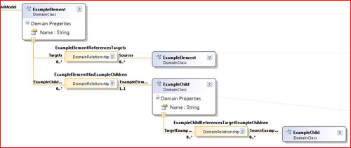
Looking at the shape map for ExampleElement, its Parent Element Path property is
ExampleModelHasElements.ExampleModel/!ExampleModel
This tells us where the ExampleElement shape should be located. The path navigates back to the model; therefore it is the diagram—that is, the presentation view of the model—that should host the ExampleElement’s own view.
Now let’s look at the shape map for ExampleChild. In most DSLs, a child embedded an extra layer down would have a longer parent element path, navigating back through its immediate parent and ending up back at the model root so that its shape’s parent is also the diagram.
But, in this case, the Parent Element Path only goes back to the Example-Element:
ExampleElementHasExampleChildren.ExampleElement/!ExampleElement
This tells us that the parent shape of the child’s shape is expected to be the ExampleModel’s shape.
Now ordinarily, the current version of the DSL Tools disallows that scenario, because it is not yet fully supported—you get a validation error. However, by setting the “Has Custom Parent Element” flag in the shape map, we can defeat that restriction. In fact, setting the flag means we have to provide the custom code to say the same thing (and we might as well have left the parent element path blank):
internal sealed partial class FixUpDiagram {
private ModelElement GetParentForExampleChild(ExampleChild childElement)
{
return childElement.ExampleElement;
}}
Now we can run the DSL and see the effects (Figure 10-9).
Figure 10-9. DSL with nested child shapes and non-nested connectors

We can add some nice behavior. Notice that we added an Expand/Collapse decorator in the parent shape, just like in a compartment shape. Collapsing the shape hides the nested shapes and their connectors automatically (Figure 10-10).
Figure 10-10. Using the Collapse button

To get this behavior, we just need to write this:
public partial class ExampleShape
{
/// <summary>
/// Decide what collapsing means for the bounds of this shape.
/// </summary>
protected override void Collapse()
{
base.Collapse(); // Remove child shapes
this.ExpandedBounds = this.AbsoluteBounds;
this.AbsoluteBounds =
new RectangleD(this.Location, new SizeD(0.5, 0.5));
}
/// <summary>
/// Decide what expanding means for the bounds of this shape.
/// </summary>
protected override void Expand()
{
base.Expand();
this.AbsoluteBounds = this.ExpandedBounds;
} }
We can also turn on built-in behavior to resize the parent as the children move around:
/// <summary>
/// Ensure that nested child shapes don't go
/// outside the bounds of parent by resizing parent.
/// </summary>
public override bool AllowsChildrenToResizeParent
{ get { return true; } }
/// <summary>
/// Ensure that parent shape is never resized too small
/// to cause children to be outside of it.
/// </summary>
public override SizeD MinimumResizableSize
{
get
{
return this.CalculateMinimumSizeBasedOnChildren();
}
}
What happens is that as you move the children to the right or bottom, the parent shape expands, and as you move them to the left or top, they stop at the parent boundary. When you drag the parent’s bounds inward, they stop before crossing a child.
Looking back at the connectors, we could hope to improve on their routing—they seem to more or less ignore the child shapes, passing right over them. Normally we’d expect the connectors to steer around obstacles. The reason here is that the connectors are located on the diagram, while the child shapes are located on their parent shapes. The connectors connect their ends to the child shapes, but the routing along the way ignores them.
(It is possible to get the connectors to find the lowest common parent of the elements they’re connecting, but some hacking of the Diagram.tt template is required. In VSSDKVisualStudioIntegrationToolsDSLToolsTextTemplatesDslDiagram.tt, comment out the loop near the end of FixUpDiagram. As recommended earlier, alter a local copy.)
In this scheme, a child is firmly fixed in its parent once it is there—you cannot easily move a child out of its parent.
Shape Containment Using Rules
Improved support for nested shapes is on the agenda for future versions. In the meantime, we can take another approach to shape containment that allows shapes to be moved between containers. While we expect this method to be rendered obsolete in future releases, it provides useful functionality in the interim, and has some tutorial value. (See the full version of the code on this book’s website.)
This model implements a state chart (Figure 10-11). States and other FlowElements such as StartPoints and EndPoints are embedded in a StateGraph. They can be interconnected by Flows, and a State can contain other FlowElements.
Figure 10-11. State Chart model
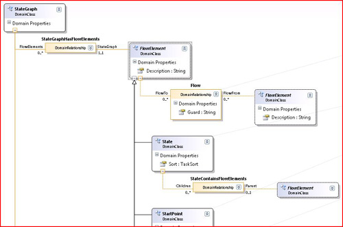
The containment relationship will be represented on the diagram by the containment of one flow element shape inside another. As the user moves the shapes around, the links change, and the Parent property can be seen to change in the properties window. It is a reference relationship—this makes issues such as parent element paths easier to deal with, though we have to ensure there are no loops (see Figure 10-12).
Figure 10-12. Running DSL with movable state shapes
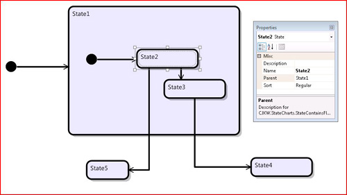
Bounds Rule
Because we don’t have the built-in feature that parents fully enclose their children, we have to write it ourselves. For this we can write a bounds rule (which we encountered earlier in this chapter). It deals with two cases.
• If the user has moved a shape (so that the height and width haven’t changed but the location has changed), we ensure that it is either fully in or fully outside every other shape rather than straddling a border. The effect is that if you move a shape onto the boundary of another shape, it snaps to be either in or out.
• If the user is resizing a shape, then the bounds rule is called repeatedly with varying height and width. In this case, we stop the bounds from being dragged across any other shapes. This means that you cannot move a shape into or out of another shape without actually moving it.
A bounds rule is a class. To register a bounds rule, override BoundsRules in the shape’s class, returning an instance of the rule.
public class StateShapeBoundsRule : BoundsRules
{
public override RectangleD GetCompliantBounds
(ShapeElement shape, RectangleD proposedBounds)
{
StateShape stateShape = shape as StateShape;
if (stateShape == null) return proposedBounds;
State state = stateShape.ModelElement as State;
if (state == null) return proposedBounds;
// Are we moving or resizing?
if (!Equal(proposedBounds.Height,
shape.AbsoluteBoundingBox.Height)
|| !Equal(proposedBounds.Width,
shape.AbsoluteBoundingBox.Width))1
{ // resizing
return RestrictResize(state, stateShape, proposedBounds);
}
else
{
return RestrictMovement(state, stateShape, proposedBounds);
}
}
}
We mustn't forget to register the rule:
public partial class StateShape
{
public override BoundsRules BoundsRules
{ get { return new StateShapeBoundsRule(); } }
}
Change Rule
To ensure that the reference link to the parent is updated as the shapes are moved, we provide a change rule (one of the types of rule listed in Table 10-3), associated with the AbsoluteBounds property of NodeShape, the common base class of all shapes.
We looked at the outline of the rule earlier. It has two jobs: to rearrange the diagram so that the children move with a moved parent, and to rearrange the relationships so that parenthood in the model is reflected in containment in the shapes. Here is the entry point of the rule. Its sole public method will be called whenever any of the properties of any NodeShape changes.
[RuleOn(typeof(NodeShape), FireTime = TimeToFire.TopLevelCommit)]
public sealed class ContainerShapeChangesRule : ChangeRule
{
public override void ElementPropertyChanged
(ElementPropertyChangedEventArgs e)
{
StateShape stateShape = e.ModelElement as StateShape;
// Ignore other types of shape
if (stateShape == null) return;
// Don't fire when loading up from file
if (stateShape.Store.TransactionManager.
CurrentTransaction.IsSerializing)) return;
// Only interested in one domain property of this class.
if (e.DomainProperty.Id == NodeShape.AbsoluteBoundsDomainPropertyId)
{
RectangleD oldBounds = (RectangleD)e.OldValue;
RectangleD newBounds = stateShape.AbsoluteBoundingBox;
HandleAbsoluteBoundsChange(stateShape, oldBounds, newBounds);
}
}
The rule will be called whenever the bounds of any NodeShape change, but we’re not interested unless this is a move rather than a resize:
private void HandleAbsoluteBoundsChange
(NodeShape stateShape, Rectangle oldBounds, Rectangle newBounds)
{
// have we moved or resized?
double dw = newBounds.Width - oldBounds.Width;
double dh = newBounds.Height - oldBounds.Height;
double dx = newBounds.X - oldBounds.X;
double dy = newBounds.Y - oldBounds.Y;
// Moved or resized? If moving, height and width don't change.
if (dw == 0.0 && dh == 0.0)
{ // moved
// Keep children by moving them too
MoveContainedStates(stateShape, dx, dy, dw, dh);
// This shape may have moved in or out of parent
UpdateParent(stateShape);
}
}
}
The shape may have moved in or out of a parent, so the domain relationship should be changed.
private void UpdateParent (NodeShape movedShape)
{
// Navigate from shape to the state it's presenting.
State state = movedShape.ModelElement as State;
// Ignore if we've somehow got some other sort of shape.
if (state == null) then return;
// Loop over all the shapes in the diagram
foreach (ShapeElement shapeElement in shape.Diagram.NestedChildShapes)
{
StateShape stateShape = shapeElement as StateShape;
// Ignore other shapes and the moved shape.
if (stateShape != null && stateShape != movedShape)
{
if (stateShape.AbsoluteBoundingBox.Contains
(movedShape.AbsoluteBoundingBox))
{
// this works because we keep smaller ones later in list
closestFit = stateShape;
}
}
}
state.Parent = closestFit == null ? null
: closestFit.ModelElement as State;
}
Notice the reference to shape.Diagram.NestedChildShapes. Every shape has a link to its containing diagram, and every diagram has a list of its shapes, NestedChildShapes. (This includes all the shapes we are dealing with—the containment scheme we use in this sample doesn’t use the NestedChildShapes relationship, so all of the shapes form a flat list under the diagram.)
Move Children
The change rule should also move the children of each shape that has moved:
childShape.Location = PointD.Add(childShape.Location, offset);
But there is an excellent example here of difficulties caused by rules firing in no particular order. If the user moves only one shape, then the change rule moves its children; the same rule then fires on them, and they move their children, and so on. This works well—each parent must only move its children, and they will move theirs.
But suppose the user selects a whole group of shapes, including both children and parents, and then moves the whole group. Each child will get moved twice! Since there is no guarantee about whether the change rules for children or parent will be fired first, it is awkward to come up with a scheme that avoids the double move.
The solution is to use a separate inline-firing rule to note all of those shapes that are being moved. Inline rules execute as soon as the change has happened—the inline rule notes the shape in the top-level transaction’s Context. When the more leisurely top-level commit rule comes along, it moves those children that have not been noted and leaves alone those children that have done their own moving.
The inline rule begins in the same way as the commit rule, but instead of actually moving the shape, just notes it in the transaction’s Context. This is accessed, and created if necessary, by MovingShapes().
[RuleOn(typeof(NodeShape), FireTime = TimeToFire.Inline)]
public sealed class ContainerShapeInlineChangesRule :
Microsoft.VisualStudio.Modeling.ChangeRule
{
public override void ElementPropertyChanged
(ElementPropertyChangedEventArgs e)
{
NodeShape stateShape = e.ModelElement as NodeShape;
if (stateShape == null) return;
if (StateShapeBoundsRule.IsDeserializing(stateShape)) return;
if (e.DomainProperty.Id == NodeShape.AbsoluteBoundsDomainPropertyId)
{
MovingShapes(stateShape.Store).Add(stateShape);
}
}
public static List<NodeShape> MovingShapes(Store store)
{
if (!store.TransactionManager.InTransaction)
return new List<NodeShape>();
Dictionary<object, object> context =
store.TransactionManager.CurrentTransaction.Context.ContextInfo;
if (!context.ContainsKey("ContainerShapeChangesRule"))
{
context.Add("ContainerShapeChangesRule", new List<NodeShape>());
}
return context["ContainerShapeChangesRule"] as List<NodeShape>;
}
}
The method in the commit-time rule that actually moves the shapes, called by HandleAbsoluteBoundsChange in the preceding code, should only do so if the shape is not already scheduled to be moved in this transaction:
private void MoveNestedStates
(NodeShape shape, double dx, double dy, double dw, double dh)
{
// Find the domain element that this shape represents.
State state = shape.ModelElement as State;
if (state == null) return;
SizeD offset = new SizeD(dx, dy);
List<NodeShape> moving =
ContainerShapeInlineChangesRule.MovingShapes(shape.Store);
// Children is the property of State that navigates the reference
// relationship StateContainsFlowElements.
foreach (FlowElement child in state.Children)
{
// Find the shape representing this FlowElement.
foreach (PresentationElement pel in
PresentationViewsSubject.GetPresentation(child))
{
NodeShape childShape = pel as NodeShape;
// We want the one that's in the same diagram as our parent.
if (childShape == null || childShape.Diagram != shape.Diagram)
continue;
// Only move it if it isn't already scheduled to move.
if (!moving.Contains(childShape))
childShape.Location = PointD.Add(childShape.Location, offset);
}
}
}
Z Order
The change rule rearranges the front-to-back ordering (“Z Order”) of the shapes so that smaller shapes are always on top of larger ones. This is desirable in a state chart, since whenever you move a smaller item over a larger one, you never want it to be obscured.
The Z Order is represented in the ordering of the diagram’sNestedChild-Shapes list—later shapes are painted later, and thus are nearer the viewer. Connectors (instances of BinraryLinkShape) are all moved to the front.
Each shape also has a ZOrder property, a double that should be maintained in correct order.
Summary
This chapter has covered a number of topics, using a variety of examples, which we hope give a flavor of the extent to which you can customize the DSL Tools. In particular, we’ve looked at the following:
• The basic mechanisms of extensibility
• Propagating change within and outside the store
• The interface to the VS Shell
• Creating menu commands
• Implementing cut and paste
• Representing relationships as containment of one shape in another
For more detail and code of all the techniques described in this (and the other) chapters, please download the solutions from the book’s website.