3. Domain Model Definition
Introduction
Chapter 2 introduced the different pieces that must be created to develop a DSL: the domain model, graphical notation and toolbox, explorer and properties window, validation, serialization, and deployment. It also introduced the DSL designer, which the DSL author uses to define the different components of the new language. This chapter describes how to define the domain model and what a domain model means in terms of the generated DSL tool.
Every DSL has a domain model at its core. It defines the concepts represented by the language, their properties, and the relationships between them. All DSL users must be aware of these to some extent, because every element that they create and manipulate while using the DSL is described by the domain model. The domain model is like a grammar for the DSL; it defines the elements that constitute a model and gives rules for how these elements may be connected together.
The domain model also provides the foundation for the other aspects of the language to build on. The definitions of notation, toolbox, explorer, properties window, validation, serialization, and deployment are all built on the domain model. It is also used to generate the programmatic API, which you can use to customize and extend the language, and which you access from templates to generate code and other textual artifacts.
The basics of domain modeling are quite simple if you are familiar with object-oriented design or object-oriented programming. This chapter describes all of the basic ideas, using the Issue State example introduced in Chapter 2 as a source of examples. It also delves more deeply into some of the finer points of domain modeling, using some modifications to the Issue State example to illustrate the key issues.
The Domain Model Designer
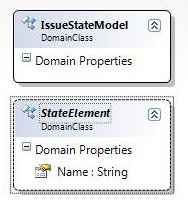
We start building the Issue State domain model in the DSL authoring solution described in the previous chapter, created using the Domain-Specific Language designer wizard. The minimal language template creates a good starting point. In the wizard, the company name is set to CJKW, the language name to IssueStateModels, and the file extension to .iss. From the resulting domain model, everything is deleted except the domain class ExampleModel and the IssueStateModelsDiagram, which are renamed to IssueStateModel and IssueStateDiagram, as shown in Figure 3-1.
Figure 3-1. Smallest valid domain model

The topic of this chapter, the domain model, is the set of elements that appear in the left-hand area of the design surface, marked “Classes and Relationships.”
Tip: Delete invalid toolbox elements
If you try to validate this domain model by right-clicking over the design surface and selecting “Validate All,” you may get a couple of errors because of elements in the Toolbox part of the definition that refer to elements that you’ve deleted. It is fine to delete these toolbox elements, because this chapter will not discuss the toolbox. Once they are deleted, the domain model should validate; it is in fact the smallest valid domain model, which contains a single domain class associated with a single diagram.
Whenever your domain model is valid, you can create a designer to try out by pressing the “Transform All Templates” button in the solution explorer and pressing F5 to build and run your design. You might even try this on the domain model shown in Figure 3-1. In the resulting designer, each .iss file will load as a blank diagram associated with a model explorer that shows a single IssueStateModel element and no means to add anything else. When the domain model is completed, the diagram will still be blank but you’ll be able to create models using the model explorer, save them as .iss files, and reload them. Later chapters will show how to complete the user interface of your designer with shapes, connectors, toolbox entries, and customized behavior.
The In-Memory Store
Before going any further in building the domain model, it is a good idea to understand something of what happens at DSL runtime inside a generated DSL tool. At the heart of a DSL tool is a set of APIs called the In-Memory store. We often call it simply the store; it is implemented by means of a class called Store, which is available to the DSL author as part of the DSL APIs. The store provides a set of basic facilities to support the behavior of a DSL tool: creation, manipulation, and deletion of model elements and links; transactions, undo/redo, rules, and events; and access to the domain model.
When a DSL tool such as the Issue State designer is launched, for example, by opening one of its files, a new Store is created and initialized by telling it about the domain models that make up the DSL that it will be executing. We’ll describe how this is done later in this chapter.
Once the store has been created and initialized, the DSL runtime executes by creating and manipulating model elements and element links. In the DSL Tools API, the abstract classes ModelElement and ElementLink provide access to all of the functionality available for creating, manipulating, and deleting model elements and links in the store. As we’ll see, the code generated for the domain model when you press “Transform All Templates” in the DSL designer mainly consists of classes derived from these. For brevity, when describing instances of classes derived from ModelElement, we often refer simply to model elements, or MELs; we similarly refer to instances of classes derived from ElementLink as links.
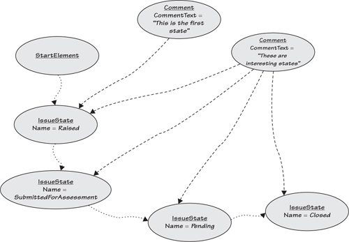
Consider the simple model of issue states shown in Figure 3-2, consisting of the states Raised, SubmittedForAssessment, Pending, and Closed, connected by transitions as shown.
Figure 3-2. Simple Issue State model as presented on screen
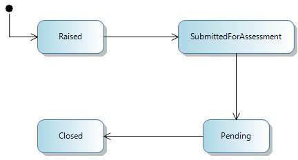
What we see in Figure 3-2 is the on-screen presentation of a model kept in the store. We’ll see later how the actual shapes and arrows are derived from the model, but let’s for the present focus on the model itself. In the store at DSL runtime, this model is represented by MELs connected by links as shown in Figure 3-3. Observe that each MEL representing an IssueState has a Name property. Each of the links has a direction, from source to target. The black circle that indicates the starting state corresponds to a MEL whose class is StartElement and which also has a Name property.
Figure 3-3. Issue State model as ModelElements and ElementLinks

In the store, each MEL is an instance of a C# class that is directly or indirectly a subclass of ModelElement. These classes are generated by the DSL Tools from the particular domain model defined by the DSL author. In fact, each of these C# classes is generated from an element in a DSL definition that we call a domain class. Similarly, each link is an instance of a C# class that is directly or indirectly a subclass of ElementLink. These classes are generated from elements that we call domain relationships. In fact, ElementLink is itself a subclass of ModelElement, so every link can do everything that a MEL can do, such as possessing properties.
Tip: Creating links between links is possible but can cause complications
It is even possible to create links sourced and/or targeted on links, links between those links, and so on ad infinitum. But you would be wise to avoid creating links to links unless you are sure that it really is the best way to get what you want; usually a simpler approach will pay dividends in maintaining your models and avoiding tricky customizations.
To avoid confusion, we will always talk about “domain classes” to refer to the parts of the domain model, and “C# classes” to refer to classes defined in the C# programming language—whether generated from the domain model or hand-written. Sometimes when talking about the generated code we’ll also mention the CLR: the Common Language Runtime, which is the basis for all of the Microsoft .NET programming languages.
Domain Classes
Domain classes are created in the DSL designer by dragging the “Domain Class” tool from the toolbox and dropping it onto the “Classes and Relationships” section of the DSL designer’s design surface. We’ve already got a domain class in our domain model, called IssueStateModel. This is called the root domain class. There can only ever be one of these in a domain model. When you run the Issue State designer to create models like the one shown in Figure 3-2, there will always be a single instance of the root domain class that corresponds to the diagram. The same is true for any DSL; you must define a single root domain class and associate it with the diagram. Thankfully, this is done automatically for you by the language templates from which you start, so unless you delete the one provided, it is already set up correctly.
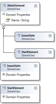
As we saw from Figure 3-3, the Issue State domain model must contain domain classes called IssueState and StartElement, both of which must define a Name domain property. Later we will define domain relationships to link these states into their owning model and to represent the transitions between them. IssueState and StartElement share some important characteristics; they have a Name and they participate in transitions. These characteristics are represented by an abstract domain class called StateElement from which these domain classes inherit.
On the toolbox is a choice between “Domain Class” and “Named Domain Class.” Dragging the latter causes the creation of a domain class that has a Name domain property. We use this tool to create a new domain class, which gets a default name of DomainClass1. Renaming this to be StateElement and setting its “Inheritance Modifier” to abstract gives the result shown in Figure 3-4.
Figure 3-4. Creating the StateElement domain class
Tip: Use the “Named Domain Class” tool to create a Name domain property
The special tool for “Named Domain Class” actually does more than just creating a domain class and giving it a Name domain property; it also creates settings so that the Name property has unique default values and special treatment for serializing cross-references. We’ll see the details later. As a rule of thumb, if you want to create a domain class whose instances have names, use the “Named Domain Class” tool.
The two domain classes IssueState and StartElement are created using the “Domain Class” tool—since they will inherit from StateElement, they do not need a Name domain property. Once the domain classes have been dropped onto the design surface and given their correct names, selecting the “Inheritance” tool and then clicking on the derived class and dragging and dropping it on the base class will create the inheritance connectors, as shown in Figure 3-5.
Figure 3-5. Creating an inheritance hierarchy
At this point, each of the new classes appears twice on the design surface as a consequence of the way the domain model design is laid out. In any domain model design, a particular domain class might appear many different times, depending on the various relationships that it has with other domain classes. However, only one of these appearances represents the full definition of the domain class; the rest are placeholders. By right-clicking on one of the placeholder appearances and selecting “Bring Tree Here” from the context menu, you can rearrange the diagram so that the definitions are conveniently placed, resulting in the reorganized layout shown in Figure 3-6. Other options to rearrange the layout include “Split Tree,” which has the opposite effect of “Bring Tree Here,” allowing you to divide up the tree into convenient sections, and “Move Up” and “Move Down,” which enable you to change the vertical order of the domain classes. Also, the little square on the edge of the StateElement domain class contains a little “–” sign; clicking in the square will cause everything hanging beneath it to collapse, leaving just the square containing a little “+” sign.
Figure 3-6. Reorganized layout of the inheritance hierarchy
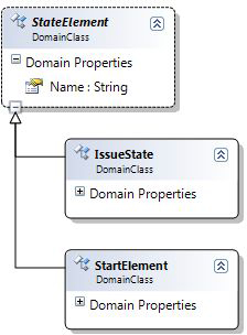
As we’ve seen from this example, domain classes can participate in inheritance hierarchies. Each domain class may have zero or one base domain class. The notation for this is borrowed from UML and consists of a solid line with a triangular open arrowhead directed toward the base domain class. The meaning is just as you would expect—the derived domain class inherits all of the domain properties and domain relationships from the base class. A domain class can be marked as abstract or sealed. An abstract domain class cannot be directly instantiated—it must instead have another domain class derived from it. A sealed domain class cannot be inherited from. Abstract domain classes appear on the diagram with a dashed border, and their names are in italics; sealed domain classes appear on the diagram with a heavy solid border.
Now we would like to give the IssueState domain class two domain properties: Description, so that the DSL user can give each IssueState some descriptive text, and Icon, so that the DSL user can associate an icon file with the state. Right-clicking over the “Domain Properties” compartment of the domain class offers a context menu containing the option “Add new DomainProperty;” by using this, the desired properties are created, as shown in Figure 3-7.
Figure 3-7. New Domain Properties added to IssueState

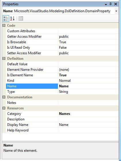
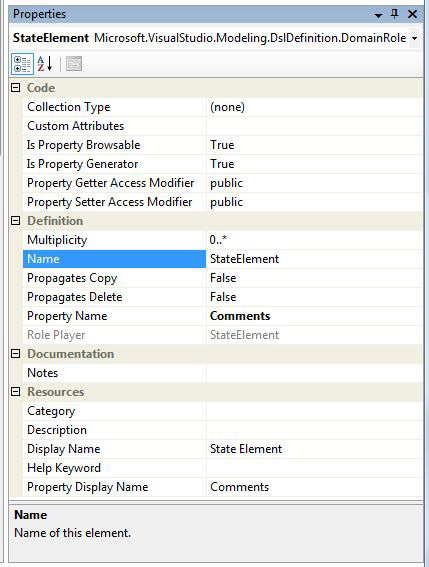
Figure 3-8 shows the Visual Studio properties window when the domain class StartElement is selected on the design surface. The “Description” setting is selected in the properties window. Every domain class has such a description, which is used to generate comments into the code and the XML Schema generated from the domain model. Under the “Definition” category are settings for the “Base Class” from which this domain class inherits, the domain class’s name, and the CLR “Namespace” into which code will be generated.
Figure 3-8. Properties window for domain class StartElement

An explanation for each entry in the properties window can be obtained by pressing the F1 key, which will open the appropriate page of the online documentation.
Figure 3-9 shows the properties window when the Name domain property of the domain class StateElement is selected.
Figure 3-9. Properties window for the Name domain property
Each domain property has a type, which may be any CLR type. In fact, the most commonly used types in a domain model are String, Boolean, and domain-specific enumerations defined in the DSL explorer (using the “Add New Domain Enumeration” command). A domain property may also be given a default value, which will be used to initialize its value when a new MEL is created.
Up to one domain property in each class may be marked as a name by setting “Is Element Name” to True as shown in Figure 3-9. Properties with “Is Element Name” set to True are treated specially in the DSL runtime; for example, their “Display Names” will be shown in various parts of the runtime user interface, such as the properties window.
Tip: “Property” has two meanings
The word “property” can cause confusion, because it has two different meanings. In a domain model, a domain class has a set of domain properties, which will govern what exists in the store when the eventual DSL is running. In the DSL designer, every element has a set of properties, which are shown in the properties window when the element is selected. One source of confusion is the fact that a domain property is just such an element. Through the properties window you can see that a domain property, such as the one called Name, has a set of properties, such as Kind. Similarly Figure 3-8 showed that every domain class has a Description property, not to be confused with the domain property called Description in Figure 3-7.
We’ve tried to avoid this confusion by referring explicitly to domain properties wherever possible. But you really have to get used to the fact that every domain property has a Name property, and in fact the Name property of the domain property shown in Figure 3-9 has the value “Name.”
Domain Relationships
Let’s add some domain relationships to our domain model. Unlike classes, we don’t have to worry about confusing domain relationships with C# relationships, because there is no such thing as a C# relationship! So we usually simply talk about relationships. Each relationship has a direction, from left to right. The left end is the source and the right end is the target of the relationship. There are two kinds of relationships, called embeddings and references. Embeddings are represented by shapes connected by solid lines, and references are represented by shapes connected by dashed lines. As we’ll see, embeddings and references have quite different characteristics, especially in the way that they influence the way that the language is visualized and serialized. We start by looking at reference relationships.
We’ll add a Comment domain class to the example and introduce a reference relationship so that a Comment can be associated with any number of StateElements, and a StateElement can have any number of Comments. The store at DSL runtime will contain MELs representing StateElements and Comments, connected by links of the new relationship as shown by the dashed lines in Figure 3-10.
Figure 3-10. Comments linked to IssueStates
First we add a new domain class called Comment using the “Domain Class” tool. We give it a domain property called CommentText, with the type String. Then we select the “Reference Relationship” tool on the toolbox, click over the Comment domain class, drag to the StateElement domain class, and release. This creates a new reference relationship whose name is automatically set to CommentReferencesStateElements. We decide that this name doesn’t quite represent the intended meaning of the relationship, so we edit it and change it to CommentsReferToIssueStates. The result is shown in Figure 3-11.
Figure 3-11. The CommentsReferToIssueStates domain relationship

Let’s take a close look at the relationship in Figure 3-11 so that we can see its various component parts. The relationship itself has a name, CommentsReferToIssueStates, in this case. The line at each side of the relationship is called a domain role, or often just role. Dashed lines indicate reference relationships, as in this case. Each role connects the relationship to a domain class, sometimes called the roleplayer for the role.
A name is shown next to each role. This is called its property name. Default property names are calculated by the DSL designer from the names of the roleplayer classes. The property name StateElements on the left-hand role is not very descriptive, so we edit it and change it to Subjects, resulting in Figure 3-12.
Figure 3-12. Property names and multiplicities on roles
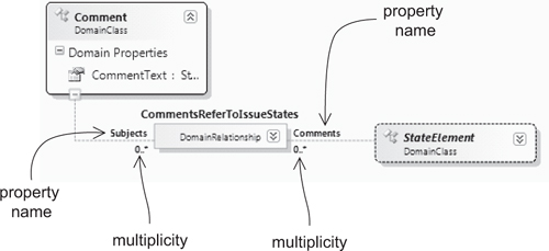
Figure 3-12 also shows that each role has a multiplicity. In this case, the source role’s roleplayer is Comment, its property name is Subjects, and its multiplicity is ZeroMany, which shows up on the diagram as 0..*; the target role’s roleplayer is StateElement, its property name is Comments, and its multiplicity is again ZeroMany.
In addition to its property name, a role has a name, which is not shown on the design surface. We’ll see later how the name of a role is used when code is generated for the relationship.
We’ve already seen that default values for the names of roles and relationships are created by the DSL designer. The default name of a role is set to be the same as the name of its roleplayer domain class. The property name of a role defaults to be the same as the name of its opposite role, pluralized in cases where the multiplicity is Many. The name of an embedding relationship defaults to be XHasY, where X is the name of the source role player, and Y is the property name of the source role. The name of a reference relationship defaults to be XReferencesY, where X and Y are calculated in the same way. This scheme usually gives a reasonably meaningful set of names for relationships and roles, and avoids a good deal of unnecessary work on the part of the DSL author. All of the names can be explicitly overridden by the author if desired, and we’ve given a couple of examples of doing that. Selecting “Reset” on the context menu for the property’s entry in the properties window will reset it to the default.
Embeddings
Some relationships are embeddings, which are displayed using solid lines. Embeddings provide a way to navigate through your model as a tree, that is, as a structure in which every element (except for the single element at the root of the tree) has exactly one parent element. This is important for several reasons. The first is that models are typically serialized as XML files, and the structure of an XML document is intrinsically a tree of elements, starting at the root element. The embedding defined in the domain model determines the structure of this tree of XML elements. Chapter 6 returns to this topic in much more detail.
Second, recall from Chapter 2 that the generated designer for your DSL has a model explorer. The embedding structure determines the organization of this explorer, because an explorer is also structured as a tree.
Third, the embedding structure also provides a default for how deletion and copying behavior is propagated through a model. By default, the deletion of an embedding parent deletes its children, while the deletion of a roleplayer MEL in a reference link deletes the link but not the other end.
Marking a relationship as an embedding places some special constraints on it, as follows:
1. The multiplicity on the target role must be either One or ZeroOne, because a MEL can only be embedded once.
2. If a domain class is a target in more than one embedding relationship, the multiplicity of all of those target roles must be ZeroOne, because a MEL of the class can only be embedded by one of those relationships at a time. Marking any one of the roles as One would make all of the other relationships impossible to instantiate.
3. In a complete domain model, every domain class except the root must be the target of at least one embedding relationship, because it would not be possible to create trees of MELs otherwise, and so the model explorer and serialization would not work.
Let’s create some embedding relationships. Taking the domain model created so far and selecting the context menu item “Validate All” produces the warning “DomainClass IssueState is not abstract, and is neither a root of the model nor embedded within it” and similar warnings for StartElement and Comment. These warnings appear because it is not possible to create trees of MELs with the domain model created so far. Therefore, it would not be possible for the Issue State designer to display a model explorer or to save the models as files. To enable the models to be trees, we must create two embedding relationships, one that embeds Comments into the IssueStateModel, and one that embeds StateElements into the IssueStateModel. These relationships are created using the “Embedding Relationship” tool, using the same gestures as the “Reference Relationship” tool. The resulting relationships are shown in Figure 3-13. Notice that the multiplicity on the right-hand roles, whose property names have been changed to Model, are 1..1, which is the default multiplicity for the target role of an embedding relationship.
Figure 3-13. Embedding relationships

Tip: Embeddings control nesting in the model explorer
The best way to think about which relationships should be embeddings is to consider your model explorer. If you want elements to be nested in the explorer, make the relationship an embedding; otherwise make it a reference.
An easy rule of thumb for beginners is to embed every non-root domain class directly in the root domain class and make every other relationship in the domain a reference. This is sometimes not ideal, but should always produce a workable DSL.
The root domain class IssueStateModel is not itself the target of any embedding relationship. Any Issue State model created at DSL runtime, such as the one depicted in Figure 3-14, will have exactly one root MEL of the class IssueStateModel. In the following chapters that describe how to associate a diagrammatic notation and a serialization with this domain model, you’ll see that both the diagram and the top-level element of the serialized file correspond to this MEL.
Figure 3-14. Root element at DSL runtime

Multiplicity
The multiplicity of a role defines, given a MEL of a particular class, how many links may have that MEL as roleplayer. There are four possible values for multiplicity.
• One: Every MEL of this class (or a derived class) must play this role exactly once. For example, every Comment must be embedded in an IssueStateModel.
• ZeroOne: A MEL of this class (or a derived class) may play this role no more than once. This is equivalent to saying that it may be linked via this relationship with zero or one MEL.
• ZeroMany: A MEL of this class (or a derived class) may play this role any number of times. For example, each Comment can refer to any number of StateElements.
• OneMany: Every MEL of this class (or a derived class) must play this role at least once.
References
We created a reference relationship earlier. References are not constrained like embeddings. In general, links from reference relationships can refer from any MEL to any other MEL. Indeed, because links are themselves MELs, you can create links between links in order to create complex graphs of objects. Bear in mind, however, that a primarily diagrammatic user interface will be used to interact with the graph at DSL runtime, so it is important to keep the design simple enough to understand through such an interface. Note, however, that although it is possible to create referencing links between any kinds of MELs or links, embedding links may not target links.
The next relationship we create is called IssueStateTransition, which goes from IssueState to itself. Figure 3-15 shows the detail of this relationship. Instances of this relationship are links that represent transitions that connect predecessor states to successor states. The multiplicity of both roles is ZeroMany—this is the default for reference relationships. This relationship has been given a domain property called Action.
Figure 3-15. The IssueStateTransition relationship

Figure 3-16 shows the on-screen presentation of an example model containing links of this relationship between the four IssueStates called Raised, SubmittedForAssessment, Pending, and Closed.
Figure 3-16. IssueStates and IssueState Transitions

In the figure, there are two transitions between the two states Pending and Closed. Each transition has a label that specifies the associated action.
Here is a case in which it is permissible to have more than one link of the same relationship between the same two MELs. Because the transitions carry actions, this makes perfect sense; the model says that a pending issue can be closed either by solving it or postponing it. If the transitions did not carry actions, then having two links between the same two states would not really make sense, so the DSL author would like to be able to prevent this.
In fact, the DSL author may specify whether or not to allow duplicate links between the same pair of MELs by setting the “Allows Duplicates” property on the domain relationship object while designing the domain model. If duplicates are not allowed, the DSL runtime will refuse to create a duplicate link.
Tip: “Allows Duplicates” can only apply to many-to-many relationships
Having multiple links between the same pair of roleplayers is only ever possible for Many-Many reference relationships in which both roles of the relationship have a Many multiplicity—any other cases have a maximum multiplicity of one, so they cannot have more than one link in any case.
Relationship Derivation
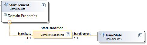
A further reference relationship is needed that connects StartElement to IssueState. Remember that a StartElement appears on the screen as a black dot connected to an IssueState. Figure 3-17 illustrates the result of creating this relationship. Note the multiplicities: Every StartElement must be connected to an IssueState via a link of this relationship—another way of saying this is that StartElements cannot validly exist in a disconnected state—and an IssueState can be connected to zero or one StartElement, but no more.
Figure 3-17. The StartTransition relationship
Now we are going to do something rather subtle. Remembering that StartElement and IssueState both inherit from StateElement, we observe that the relationships StartTransition and IssueStateTransition are rather similar. They both connect StateElements to StateElements. We can actually capture this similarity in the model by introducing inheritance on the relationships themselves. Using the “Reference Relationship” tool, we create a new relationship between StateElement and itself, which we call Transition. The “Inheritance Modifier” of this relationship is set to abstract, which means that it is not possible directly to create links of it.
Now the relationships StartTransition and IssueStateTransition are both derived from the abstract relationship Transition. This is shown by the portion of the domain model illustrated in Figure 3-18. To create this part of the model, the option “Show as Class” was selected on the relationships Transition, IssueStateTransition, and StartTransition, which caused extra shapes representing the relationships themselves to appear on the DSL designer’s design surface (see Figure 3-19). This facility allows inheritance, and indeed any other kind of relationship, to be set up between domain relationships.
Figure 3-18. The abstract relationship Transition

Figure 3-19. Relationships shown as classes in a hierarchy

The basic rule for relationship derivation is that a link of a derived relationship can be considered as if it were a link of the base relationship. This is the same as for normal classes: An instance of the derived class can be considered as if it were a link of the base class. Relationships are special, though, because they always have two roleplayer classes. If a link of the derived relationship can be considered as if it were a link of the base relationship, then the roleplayer MELs must have classes consistent with the roleplayer classes of the base relationship. That is, the roleplayer classes for a derived relationship must be derived from, or the same as, the corresponding roleplayer classes for the base relationship.
For example, a link of IssueStateTransition connecting two IssueStates can be considered as if it were a link of Transition connecting two StateElements. Similarly, a link of StartTransition connecting a StartElement to an IssueState can also be considered as a link of Transition connecting two StateElements. Asking the relationship Transition for all of its links will give back the total of the IssueStateTransition and StartTransition links.
Generating a Designer with No Shapes
Having used the concepts described so far to define the domain model in the DSL designer, a working Issue State designer can be generated and launched in the Debugging project as explained in Chapter 2.
The generated Issue State designer has a blank diagram and an empty toolbox, because these elements of the language have not been defined—defining these is the subject of later chapters. However, it does have a fully working explorer and properties window. Figure 3-20 shows the explorer when one Comment and three IssueState elements have been created, and the menu provides the option to add further elements. Notice that the structure of the explorer corresponds exactly to the embedding relationships defined in the domain model.
Figure 3-20. Explorer for Issue State target designer

Tip: Links of many-to-many relationships cannot be created through the explorer or properties window
This designer is not fully functional with respect to the domain model because it is not possible through the explorer or properties window to add new IssueStateTransition links. To do that, it is necessary to create links from the toolbox; we’ll see how to do that in later chapters.
The Generated Code
So far we’ve explained how to create the domain model. On its own, this would just be a structure within the DSL designer that represented the user’s wishes about the DSL that he or she would like to build. In order to bring these wishes to life, code has to be generated to implement the domain model using the “In Memory Store” and other features of the DSL Tools. This code is generated by pressing the “Transform All Templates” button in Visual Studio’s solution explorer for the DSL Authoring solution.
From a practical perspective, it is very useful to understand the generated code, not least because customizing the generated DSL tool requires the DSL author to interface to this code and because there are some restrictions to what is allowed in domain models that result from the fact that valid code must be generated. At this point, we focus on the generated code and the elements of the DSL Tools framework that it uses.
The explanation can be considerably simplified by use of another DSL, namely, the graphical language implemented by the Class Designer tool that forms part of Visual Studio 2005. This tool will take a body of code written in C# (or other CLR languages) and create diagrams of the classes in it that show how they relate to each other.
Figure 3-21 shows such a diagram that illustrates the C# classes generated from the domain classes created during this chapter. Each rectangle in Figure 3-21 corresponds to one C# class. Observe in the header of each rectangle the little symbol that indicates the base class. By default, each class inherits from ModelElement. Each class is generated in the CLR namespace specified in the properties window for the corresponding domain class. By default, all classes are generated in the same namespace, which is the one specified in the language wizard when the language template was originally unfolded.
Figure 3-21. Class diagram of generated domain classes

For our purposes, the compartments containing Fields, Methods, and Nested Types, which are only of interest to more advanced developers, have been closed up. What remains are the properties of each class. There are two kinds of property: those that have been generated directly from the domain properties specified in the domain model, and those that have been generated from the roles of the relationships, where the name of the generated property is the property name of the role. These are shown in Figure 3-21 using different display options provided by the Class Designer. The properties generated from domain properties are shown inline in the class symbols themselves, while those generated from roles are shown as arrows on the diagram.
There are two kinds of arrows, those with single arrowheads and those with double arrowheads. The ones with single arrowheads simply mean that the property has the type of the class at the head of the arrow; so for example, the arrow from StateElement to IssueStateModel marked Model means that the class StateElement has a property called Model whose type is IssueStateModel. This is a diagrammatic convention derived from UML that helps to visualize properties whose type is a class shown on the diagram.
The arrows with double arrowheads mean that the type of the property is a collection whose contents are instances of the type at the head of the arrow. This can be illustrated more clearly by expanding the part of the diagram that deals with the relationship CommentsReferToIssueStates, as in Figure 3-22. In this figure, the property of StateElement called Comments is labeled with its type LinkedElementCollection<Comment>. The generic class LinkedElementCollection<T> is part of the DSL Tools API. Every relationship role that has a multiplicity of ZeroMany or OneMany generates a property whose type is LinkedElementCollection<T>, where T is the class at the opposite end of the relationship. Generic classes are a CLR feature introduced in .NET 2.0. One of their important strengths is the ability to define strongly typed collections, that is, collections where it is possible to specify the type of their contents at compile time. This strength has been used extensively in the design of the API generated from a domain model by the DSL Tools.
Figure 3-22. Class diagram for CommentsReferToIssueStates

Recall that in the domain model the role whose roleplayer is StateElement has a property name of Comments. This is used to generate the Comments property on the C# class StateElement. This role has a multiplicity of ZeroMany, so the type of the generated property is LinkedElementCollection<Comment>.
Figure 3-22 also shows explicitly the class CommentsReferToIssueStates, which is generated from the corresponding relationship in the domain model. The header of the class shows that it inherits from ElementLink. It has two arrows leaving it, one pointing at StateElement and called StateElement, and the other pointing at Comment and called Comment. These represent properties generated from the domain roles onto the relationship class itself. The names of these properties are generated from the name of the role, as distinct from its property name. Such a property can be used in code to navigate from an individual link to the associated roleplayer object.
Tip: The role’s name is always singular; the property name is often plural
Note that the name of the role is always singular, whereas the property name is plural whenever the multiplicity is Many. Maintaining this convention can help considerably with the readability of the generated code.
Classes generated from domain relationships such as this one are used in circumstances where the DSL author wishes to deal explicitly with the links of the relationship itself. In this particular example, that is not very likely; the normal DSL author only needs to use the Comments and Subjects properties on the roleplayer classes to create and manipulate configurations of Comment and StateElement objects together with their intervening links.
Using the Generated Code
The generated code has been carefully designed to give a convenient API for DSL authors as a basis for their own DSL extensions and code generation templates. Whenever you want to write code against this API, you must include the following using statements:
using Microsoft.VisualStudio.Modeling;
using Microsoft.VisualStudio.Modeling.Diagrams;
...
First, note that any change to the store must be performed in the context of a Transaction. If you want to add or remove elements or relationship links, or you want to change their properties, you must open a Transaction like this:
using (Microsoft.VisualStudio.Modeling.Transaction t =
this.Store.TransactionManager.BeginTransaction("operation name"))
{
// ... change store in here ...
t.Commit();
}
If an exception is thrown that is not caught within the using block, or if you explicitly Rollback() the transaction, then all the changes performed within the block will be undone. Also, when an Undo() or Redo() operation is performed, all of the changes made in the store within the transaction are undone or redone as a unit. Indeed, the name given as a parameter to the BeginTransaction() method is the name that will show in the eventual DSL as an item on the Visual Studio undo stack.
Having defined the Issue State domain model and generated code from it, the DSL author can write code such as this:
using (Microsoft.VisualStudio.Modeling.Transaction t =
this.Store.TransactionManager.BeginTransaction("example"))
{
IssueState state = new IssueState(store);
state.Name = "TestState";
Comment comment = new Comment(store);
comment.CommentText = "This is an interesting state";
comment.Subjects.Add(state);
t.Commit();
}
In fact, before this code will work, the store must be initialized. In addition to the C# classes generated for the classes and relationships in the domain model, a further C# class is generated that corresponds to the domain model itself. This class implements a variety of helper methods for creating and deleting objects, giving runtime access to the domain model, and enabling and disabling diagram rules. For our example, this class is called IssueStateModelsDomainModel and is derived from the class DomainModel supplied with the DSL Tools framework. This class is used for initializing the store. A store is created and initialized using its constructor:
Store store = new Store(typeof(IssueStateModelsDomainModel));
The result of this call is to create a new Store, initialized so that it can contain instances of the domain classes and relationships defined in the domain models passed in as parameters to the constructor. You can in fact pass in as many domain models as you like; a store initialized with multiple domain models can contain MELs and links from any of those models.
More about Domain Classes
The remaining sections of this chapter delve into some of the finer points of domain models and the code generated from them. Broadly speaking, they are concerned with three topics: customization of the generated code, customization of the generated user interface, and code customization options. Quite a lot of customization is possible using the DSL Tools’ built-in code generation, but when the DSL author wishes to stray outside of those possibilities—to step up onto a higher customization plateau—there are additional options to enable this. These options are briefly covered here; later chapters build on these concepts and discuss the topic of customization in greater depth. Readers who are particularly interested in code customization might like to skip ahead and take a brief look through Chapter 10, where all the material on custom code is brought together.
Figure 3-23 shows the properties window when a domain class is selected. In the “Definition” category, the property “Namespace” specifies the CLR namespace where the C# class will be generated. The “Code” category provides further options for customizing the generated code. We’ve already seen the use of the “Inheritance Modifier” property, which can be set to none, abstract, or sealed, causing the generated class to be correspondingly marked. You should mark a class as abstract if you don’t want to create any instances of it in your running DSL. If you don’t mark it as abstract, then the DSL Tools will assume that you want to create instances of it and will generate code and validate your domain model accordingly. Marking a class as sealed can be useful for restricting the ways in which a designer can be extended and thus can reduce the costs of supporting it.
Figure 3-23. Properties for a domain class
By default, all of the C# classes generated from domain classes are public. You can specify that a generated class is internal using the “Access Modifier.” Again, this is a way to reduce the ways in which a designer can be extended.
A very common approach to customizing a generated DSL tool is to add methods and properties to the generated C# classes by hand. Partial classes are a feature introduced with .NET 2.0 that permit the definition of a single class to be split across multiple files. This is extremely useful in code generation scenarios where part of the class’s definition is generated and another portion written by hand; it means that hand-written code is not overwritten when the rest is regenerated. The DSL Tools exploits this capability throughout its generated code. For each domain class a partial class is generated so that DSL authors may write their own matching partial class(es) that add custom behavior to that generated by the DSL Tools. Such a partial class might, for example, declare that the class conforms to a particular interface, or add methods, fields, or properties to the generated code.
Sometimes, though, it is necessary to inhibit some of the code generation so that the DSL author can customize at a deeper level. For this purpose, two Boolean flags are available on the definition of a domain class. “Has Custom Constructor,” when set to true, will stop the generation of a constructor for the generated class. This is useful where the DSL author needs to apply customized initialization to a particular class. “Generates Double Derived,” when set to true, causes the generation of two classes: an abstract base class, containing all of the generated methods, and a concrete derived partial class that only contains a constructor. This pattern allows any virtual member in the generated class to be overridden by DSL authors, who can create their own partial section for the concrete derived class that overrides the base class. Customization sections in later chapters will demonstrate the use of this capability.
A further customization option, which applies to domain classes, relationships, properties, and roles, is given by the ability to add any extra CLR attributes that the DSL author desires through the “Custom Attributes” setting in the properties window. These attributes will be added to the generated code. This can be a useful general-purpose way to add data to the domain model that could be used to extend its use, for example, to help generate code for different purposes.
Properties of a domain class in the “Resources” category govern aspects of the user interface of the generated DSL Tool. These properties generate entries in a resources (.resx) file included in the DSL authoring solution. The “Display Name” is used whenever the domain class is identified in the user interface at DSL runtime. This is useful if the DSL is intended for use in a country that speaks a different language, or if the desired user interface name of the class is one that cannot validly be used as the identifier of a C# class.
Each domain class is also given a “Description.” This is used to create a summary comment in the generated code; it is also used to generate annotations on the generated XML Schema, which provide extra IntelliSense assistance to a DSL user hand-writing XML in the target domain.
The “Help Keyword” is used to associate an optional keyword with the domain class that can be used to index F1 Help.
DomainClassInfo
When the store is initialized with a domain model, a DomainClassInfo object is created for every domain class in the domain model. Objects like this provide runtime access to the domain model, enabling the caller to discover the properties of a domain class, what domain properties it contains, which relationships it participates in, and its inheritance hierarchy. Objects like these are useful for writing programs that need to operate across the store, independently of the specific domain model that is loaded—programs such as generic user interfaces, debugging tools, serialization tools, animation tools, and so on.
This code fragment illustrates how to acquire a DomainClassInfo object from a suitably initialized store and query it:
IssueState s1 = new IssueState(store);
DomainClassInfo dci = s1.GetDomainClass();
string className = dci.Name;
ReadOnlyCollection<DomainPropertyInfo> = dci.AllDomainProperties;
ReadOnlyCollection<DomainRoleInfo> = dci.LocalDomainRolesPlayed;
Tip: Every DomainInfo object has an Id property
Every Info object—DomainClassInfo, DomainPropertyInfo, DomainRelationshipInfo, DomainRoleInfo—has an Id property that gives a unique System.Guid for the Info object. Some of the DSL Tools’ APIs require these Ids to be passed as parameters, although most require references to the objects themselves.
The class DomainClassInfo also provides several static utility methods that are mainly concerned with manipulating the names of MELs. These methods could also have been implemented on the class ModelElement but have been made static methods on DomainClassInfo in order to reduce the surface area of ModelElement and thus improve the IntelliSense experience for generated classes that derive from ModelElement.
More about Domain Properties
The customization settings for a domain property are accessed using the properties window when the domain property is selected, as shown in Figure 3-24.
Figure 3-24. Properties for the Name domain property
Most domain properties in a DSL are typically typed as String, Boolean, or an enumeration defined as part of the DSL. These enumerations can be specified either as public or internal. An enumeration may optionally be marked as Flags, in which case its values are interpreted as a bitfield.
Tip: Domain properties of Flags types have a custom editor with checkboxes
When a domain property’s type is an enumeration marked as Flags, the property will automatically show up in the properties window of the generated tool with a custom editor that allows you to set the bitfield using checkboxes.
In fact, a domain property may have any CLR value type, including types defined outside the DSL. The default value for the domain property, if there is one, must be a string that converts validly to a value of the domain property’s type.
Normally, a domain property generates a public CLR property on the generated class. It’s possible to separately specify the access modifier for the generated getter and setter via “Getter Access Modifier” and “Setter Access Modifier” to be private, internal, or protected—in fact, any of the access modifiers allowed by the CLR. The DSL author might place such restrictions in order to limit the way that the domain property can be used, and hence in order to limit support costs.
We earlier saw that one domain property in a class may be marked as being a name (by setting “Is Element Name” to True). When this is set, a built-in algorithm is used to create default values for the name domain property that are unique for the MEL and its siblings within the context of the same embedding MEL. The default algorithm appends a number to the name property’s default value, or to the domain class name if there is no default value. For example, the Name domain property in the StateElement domain class has no default value. This means that the default unique names for IssueStates within the same IssueStateModel will be “IssueState1,” “IssueState2,” “IssueState3,” and so on.
This algorithm may be overridden by defining a class that derives from the built-in ElementNameProvider class, implementing its SetUniqueName() method with the desired algorithm, and setting the “Element Name Provider” property to refer to the new class.
When the generated designer is running, selecting a shape on the diagram or an entry in the model explorer will cause the domain properties defined for the domain class of the selected MEL to show up in the properties window, named by their “Display Name.” Domain properties can be hidden from the properties window by marking them with “Is Browsable” set to False, and if they are browsable they will show up in gray and with editing disabled if they are marked “Is UI Read Only” set to True. The properties window is organized into categories, and the domain property’s “Category” can be specified by a string. If no category is specified, the property will appear in the category “Misc.” When a property is selected in the properties window, its “Description” will appear, giving the DSL user some help in understanding its meaning. The “Description” is also emitted in the property summary comment in the generated code and as an annotation in the generated XML Schema.
Calculated Properties
An important customization is the ability to define calculated domain properties. These are properties that have no storage and only a getter. The value for the domain property is calculated, when called, from data acquired elsewhere, for example, from other domain properties on this or other MELs. Setting a property’s “Kind” to Calculated causes the generation of code that requires the DSL author to implement a method, in a partial class, called GetXXXValue(), where XXX is the name of the calculated domain property. This method can use the generated API to navigate to the data it needs to calculate the correct result. If the DSL author forgets to implement this method, then the DSL will fail to compile.
There is a subtlety that arises when defining a calculated domain property. We’ll see later that making changes to the store causes the firing of rules, which are used to update objects in the store, and events, which are used to make updates external to the store. In particular, rules are used to fix up the diagram when MELs are changed. When a domain property is defined as Calculated, rules and events do not automatically fire when the calculated value changes. Instead, the DSL author must explicitly cause rules and events to be triggered, using the method NotifyValueChange() on the class DomainPropertyInfo. We’ll describe this class shortly.
A further possibility for the “Kind” of a property is called CustomStorage. A domain property marked in this way will not generate any field to hold its data. Instead, the DSL author must define, in a partial class, some other way to store the value for the property, and must also define methods GetXXXValue() and SetXXXValue(), which will access and update the property’s stored value. This capability can be useful when the “Type” of the property needs special initialization or lifetime management.
DomainPropertyInfo
When the store is initialized with a domain model, a DomainPropertyInfo object is created for every domain property in the domain model. This object provides runtime information about the corresponding domain property. It also offers some useful methods:
• The method GetValue(ModelElement element) can be used to get the value of this domain property for the ModelElement passed as a parameter. It returns a System.Object.
• The method SetValue(ModelElement element, object value) can be used to set the value of this domain property for the ModelElement passed as a parameter.
• The method NotifyValueChange(ModelElement element) can be used to trigger events and rules that depend on this property on this ModelElement. This is for use in scenarios where the property is calculated, where these events and rules would not otherwise be triggered when the calculated value changes.
The following code fragment (which must be run in the context of a transaction) shows how to acquire a DomainPropertyInfo object from a suitably initialized store and use it to update the associated domain property’s value:
IssueState s1 = new IssueState(store);
DomainClassInfo dci = s1.GetDomainClass();
DomainPropertyInfo dpi = dci.FindDomainProperty("Name", true);
dpi.SetValue(s1, "NewName");
string newValue = (string)dpi.GetValue(s1);
More on Domain Relationships and Roles
First, note that because relationships are implemented using classes, all of the customization and tuning that applies to a domain class can also be applied to a domain relationship. This section explores some of the extra customization options that particularly apply to the roles of a relationship. The properties window when a role is selected is shown in Figure 3-25.
Figure 3-25. Properties for a domain role
We explained earlier how domain roles cause properties to be generated on the roleplayer classes. In fact, a setting on the role can be used to inhibit the generation of these properties, if desired. This is done by setting “Is Property Generator”—seen in Figure 3-25—to False. The DSL author would normally only do this in order to reduce the size of the DSL’s generated API, or possibly to avoid name conflicts in the generated code. Similarly, when the properties are generated, the DSL author can restrict their external visibility using “Property Getter Access Modifier” and “Property Setter Access Modifier,” which have similar effects to the corresponding settings on a domain property.
If the role has a multiplicity of ZeroOne or One, properties generated from the roles will appear in the properties window at DSL runtime just like any other properties, allowing the single roleplayer to be selected, and similar data may be used to fine-tune these properties: “Property Display Name,” “Description,” “Category,” and” Is Property Browsable.”
We saw earlier in the chapter that a role with Many multiplicity causes the generation of a property whose type is LinkedElementCollection<T>, where T is the domain class at the other end of the relationship. The DSL author can define a custom collection to be used instead of this, for example, by creating an index to help performance on a collection containing many elements. The setting for “Collection Type” can be used to apply such a customization.
By default, an embedding relationship will cause deletion to be propagated from source to target. If the source roleplayer is deleted, then the embedding link must be deleted—it is not possible for a link to exist without a roleplayer at each end—and as a consequence of the link being deleted, the target roleplayer will also be deleted. On the other hand, a reference relationship will not propagate deletion. This is often the behavior required from a DSL—but not always. Some scenarios exist for which we want to customize this deletion behavior. For example, in the Issue State model, the relationship between a StartElement and its associated IssueState is a reference relationship. If the IssueState MEL is deleted, then the link between them will go, but the StartElement will remain. But we would definitely like the StartElement to be deleted, too—it makes no sense on its own. By marking the source role of StartTransition as PropagatesDelete, we can achieve this. Now, when the StartTransition link is deleted, the source roleplayer—the StartElement—is deleted too. This topic is discussed further in Chapter 5, which describes how to customize the delete behavior using the DSL Details window.
Programmatically, a MEL can be deleted by calling its Delete() method. By default this will cause deletion to be propagated as described in the paragraph above. It is, however, possible to specify as parameters to the call to Delete() a set of roles through which the delete is not to be propagated. This is done by passing the Ids of the associated DomainRoleInfo objects, described below.
Accessing Links
If you want to get access to the actual links of a relationship, the generated API provides static methods on the C# class generated for the domain relationship to do this. Three of these for the class IssueStateTransition can be seen in Figure 3-26. Their signatures are as follows:
/// <summary>
/// Get the IssueStateTransition links between two given IssueStates.
/// </summary>
public static ReadOnlyCollection<IssueStateTransition> GetLinks
(IssueState source, IssueState target)
/// <summary>
/// Get the IssueStateTransition links targeting an IssueState.
/// </summary>
public static ReadOnlyCollection<IssueStateTransition> GetLinksToPredecessors
(IssueState nextStateInstance)
/// <summary>
/// Get the IssueStateTransition links sourced on an IssueState.
/// </summary>
public static ReadOnlyCollection<IssueStateTransition> GetLinksToSuccessors
(IssueState previousStateInstance)
Figure 3-26. Generated methods for IssueStateTransition

The use of the GetLinks() method is illustrated in the following code example:
using (Microsoft.VisualStudio.Modeling.Transaction t =
this.Store.TransactionManager.BeginTransaction("example"))
{
IssueStateModel model = new IssueStateModel(store);
IssueState s1 = new IssueState(store);
model.States.Add(s1);
IssueState s2 = new IssueState(store);
model.States.Add(s2);
s1.Successors.Add(s2);
s1.Successors.Add(s2);
ReadOnlyCollection<IssueStateTransition> links =
IssueStateTransition.GetLinks(s1, s2);
links[0].Action = "solve";
links[1].Action = "postpone";
t.Commit();
}
More on Relationship Derivation
Relationship derivation can be very useful for all of the same reasons that class inheritance is useful—it allows common structure and behavior to be shared in common base classes. For example, if the author of the IssueState model wished to specify some rules or behavior that applied to all transitions, whether they are start transitions or normal Issue State transitions, the Transition relationship is the place to do it.
However, it does cause some subtleties in the generated code. Furthermore, it also imposes a few restrictions on which multiplicities are allowed for the various roles. Let’s look at the multiplicities first.
Remember that each role causes the generation of a property on the roleplayer domain class. In the case of the StartElement role on the StartTransition relationship, the generated property on the StartElement C# class is called StartState and returns the associated IssueState. Similarly, for the Previous role on the Transition relationship, the generated property on the StateElement C# class is called Successors and returns the associated StateElements.
The restrictions on multiplicity are a logical consequence of the fact that the links navigated via the base generated property (Successors) must be a superset of the links navigated via the derived generated property (StartState). This follows from the definition of relationship derivation—every link of StartTransition is also a link of Transition.
For example, given a StartElement, the links navigated via the StartState property must be a subset of the links navigated via the Successors property. In fact, in this model, they must be the same set of links, because there is no other relationship derived from Transition that is sourced on StartState.
These restrictions imply that it is an error, if the multiplicity of the base role is ZeroOne or One, for the multiplicity of the derived role to be ZeroMany or OneMany. Given the multiplicity of the base role, there could never be more than one link.
It’s also possible, although unusual, to create misleading multiplicity combinations, which will cause the DSL Tools to issue warning messages. Here are a couple of examples.
• If the multiplicity of an abstract base role is ZeroOne or One, and there are two or more derived roles that have the same roleplayer class, they must all have the multiplicity ZeroOne, because only one of them could validly be instantiated at a time.
• If the base relationship is not abstract and has an end with a multiplicity One, then there is no point in creating a derived relationship, because we know that the base relationship has to be instantiated directly.
Tip: The DSL designer validates all of the multiplicity rules
If the complexity of this description defeats you, then don’t worry. Unless you try something very subtle you are unlikely to trip up against these issues, and if you do, the DSL designer validates all of these rules before it generates a DSL.
There’s a restriction of the C# type system that impacts the code that is generated for derived relationships. It is not possible in C# to override the definition of a virtual property with a property of a more derived type—the type of the overriding property must be exactly the same as the type of the overridden one. We can see this restriction by looking at the code generated for the relationship IssueStateTransition. Referring to Figure 3-27, there are properties called Next and Previous on the classes Transition, IssueStateTransition, and StartTransition, all generated from the names of roles. For IssueStateTransition and StartTransition, their types have not been shown, to avoid clutter on the diagram. In fact, they are all virtual properties that have the same return type—StateElement—even though it would be more in keeping with the model for the Previous property on StartTransition to refer to StartElement, and its Next property to refer to IssueState. But because of the built-in restriction of the language, these properties must all have the same type, and code is generated that actually checks the correct type at runtime.
Figure 3-27. Classes generated for derived relationships

Slightly different considerations apply for the properties generated on roleplayer classes, such as the properties Predecessors and Successors defined on StateElement. These properties may be superseded in derived classes by properties with a more derived type. This can be seen for the class IssueState, which has also defined these properties to be called Predecessors and Successors. In the generated code, these properties are marked as new, to explicitly specify that they are intended to replace the inherited properties. In fact, because of the semantics of derived relationships, both the inherited and replacing properties will return exactly the same values.
In practice, the effect on the DSL author of these considerations is minimal. A derived relationship may use either the same or different names for the role and property names of derived relationships, and the code generator will take care of it, generating the appropriate pattern for each case.
DomainRelationshipInfo and DomainRoleInfo
DomainRelationshipInfo is derived from DomainClassInfo and provides runtime access to information about the corresponding domain relationship. It defines the following important properties.
• AllowsDuplicates returns a Boolean value indicating whether duplicate links are allowed.
• IsEmbedding returns a Boolean value indicating whether the relationship is an embedding.
• DomainRoles returns a collection of two DomainRoleInfo objects, each of which provides runtime access to information about the corresponding domain role.
More about the Store
This final section offers a few points of interest about the store that can be helpful when writing code customizations. Much more detail can be found in the online documentation, which can be installed when you install the Visual Studio SDK.
Looking Up Elements
The class ModelElement defines a property called Id. The value of this property is a Guid (Globally Unique Identifier), which is allocated when the element is first created in the store (System.Guid is a structure provided by the .NET framework). The value of this property may be used to find the element in the store. Given a store and an Id, the following line of code will find the element with the Id, or return null if it is not present:
store.ElementDirectory.FindElement(id);
The method GetElement(id) can be used similarly but will throw an exception if the element is not found.
Model serialization, described in Chapter 6, provides the option to save the Id of an element so that it can be preserved across model reloads. This would be necessary whenever an element’s Id can be saved externally and used to access it later.
Partitions
A store can be divided into distinct partitions. When a ModelElement is created, it is possible to specify the partition that it is created in. The main purpose of partitions is to enable a single store to contain multiple models; for example, each partition might be associated with a separate model file. The current version of the DSL Tools does not make any use of the partitioning facility of the store.
Rules
Another important concept when working with models in the store is rules. We’ll encounter these when writing customizations in later chapters, especially Chapter 7 and Chapter 10. A rule is defined when the DSL author needs to propagate changes to elements in the store so that other elements are also affected. For example, rules are used to fix up the diagram automatically whenever the model changes. We’ll leave the details for later chapters. For now, notice some essentials, as listed here:
• The rule is a class that inherits from AddRule, ChangeRule, DeletingRule, RolePlayerChangedRule, or one of several other categories. The single overridable method provides an argument that yields the details of the change.
• The rule has a RuleOn attribute that specifies which class it applies to.
• The rule is executed within the transaction in which the change occurred; it may make changes that cause further rule firings, which are added to the queue to be fired.
• You must register your custom rules in the DomainModel class:
public partial class IssueStateModelsDomainModel
{
protected override Type[] GetCustomDomainModelTypes()
{
return new System.Type[] { typeof(MyNewRule) };
}
}
DomainModelInfo
A DomainModelInfo object is the top-level entry point giving runtime access to data for the entire domain model. This code fragment shows how to acquire a DomainModelInfo object from an initialized store, and how to query it for its constituents:
Store store = new Store(typeof(IssueStateModelsDomainModel));
...
DomainModel dm = store.GetDomainModel<IssueStateModelsDomainModel>();
DomainModelInfo dmi = dm.DomainModelInfo;
ReadOnlyCollection<DomainClassInfo> domainClasses = dmi.DomainClasses;
ReadOnlyCollection<DomainRelationshipInfo> domainRelationships =
dmi.DomainRelationships;
Summary
In this chapter we talked about defining domain models for Domain-Specific Languages. These models are the foundation for language definition. By now you should have learned:
• How to build a basic domain model using the DSL designer
• What the DSL domain model notation means
• How to do basic programming against the DSL API to make a model
All of the other aspects of the language definition described by the next few chapters—notation, serialization, validation, code-generation, and user interface—are based on having a domain model that properly represents the concepts, properties, and relationships of the domain.