5. Creation, Deletion, and Update Behavior
Introduction
Chapter 2 introduced the different aspects of the definition of a DSL: the domain model; the presentation layer, including graphical notation, explorer, and properties window; creation, deletion, and update behavior; validation; and serialization. Chapter 3 described the first aspect, the domain model, and Chapter 4 described the presentation aspect. This chapter focuses on how to define update behavior, that is, creation of elements using the toolbox and explorer, editing of properties of elements through the properties window, and deletion of elements.
Element Creation
When a new element is created in the store, it must be linked into the embedding tree—that is, it must be the target of one embedding link, and there must be a path back through embedding links to the root element. It cannot otherwise be presented on the diagram or serialized.
When the user drags from an element tool onto the diagram, this gesture:
• Creates a new element of the class determined by the Tool definition (in the DSL explorer under “EditorToolboxTabs”).
• Creates a link or links between the new element and the existing ones. This behavior is determined by the element merge directive of the target element—that is, the one the tool was dragged onto.
• Fires rules that update the diagram to show the new element. These are determined by the shape maps, as we saw in the previous chapter.
The last point is important. We rely on “fixup” rules to maintain, on the screen, a presentation of what is going on in the model. All the techniques in this chapter—and indeed much of the custom methods you might write—deal only with the domain classes and domain relationships. Once we’ve set up the shapes and their mappings to the domain model (as discussed in Chapter 4), we can just work with the domain model, leaving the diagrams to look after themselves.
The Toolbox
Tools are defined in the DSL explorer under “EditorToolboxTabs YourTabTools.” You need to define a tool for each item you want to appear on the toolbox (Figure 5-1). The tab name is the heading that appears above each group of tools in the toolbox. By default, you have just one tab, named after your language, but you can add more tabs in the explorer if you wish.
Figure 5-1. The toolbox for the Issue Tracking DSL

There are two kinds of tools: element tools and connection tools. At runtime, you operate an element tool by dragging it from the toolbox to the diagram; for a connection tool, you click it and then drag it between the two elements you want connected (or click them in succession). The most common scheme is to provide an element tool for each class that is mapped to a shape on the diagram and a connection tool for each relationship mapped to a connector.
Each tool has a name, caption, tooltip, toolbox icon, and help keyword; these are set in the properties window (Figure 5-2). In addition, an element tool can have a cursor icon that shows while you are dragging it, and a connection tool can have source and target cursor icons that show while waiting for you to select the source and target of the connection.
Figure 5-2. Toolbox definition for the Issue Tracking DSL

Each element tool is associated with a single domain class. Unless you write custom code, the tool creates a single element of this class each time the user drags from the tool to the drawing surface. The properties of the new element have their default values as specified in the DSL definition. The construction of relationships between the new element and the existing model is governed by an element merge directive, which we’ll look at shortly.
Each connection tool invokes a specified connection builder, which governs what elements may be created and the result of creating them. You might expect that by analogy with the element tools, each connection tool would be defined to create instances of a particular domain relationship class; but no, a connection builder can be defined so as to instantiate any of several relationships, depending on the classes of the two elements the user wants to connect.
We’ll come back to connection tools later in this chapter; first let’s focus on creating elements.
Element Merge Directives
Element merge directives (EMDs) control what relationships are constructed when one element is merged into another. A merge happens when one of the following occurs:
• The user drags an element from the toolbox onto the design surface (or one of the shapes on it).
• The user creates an element using an “Add” menu in the DSL’s explorer.
• The user adds an item in a compartment shape.
• The user moves an item from one swimlane to another.
• Your custom code invokes the merge directive, for example, to implement a paste operation (as described in Chapter 10).
In each of these cases, there are two elements to be connected, but there may be many different possible links between them. The job of the EMD is to determine which links are constructed. An EMD also has a disconnect function that is invoked when an element is to be moved between parents—for example, from one swimlane to another.
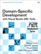
The simplest and most common case is when there is an embedding relationship between the two domain classes. In the Issue Tracking example, each IssueProjectModel element has projects and comments (Figure 5-3). An IssueProjectModel element is represented by the diagram, and the two others are each mapped to shapes.
Figure 5-3. IssueProjectModel embeds Projects
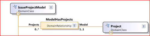
When the user drags from the Project tool to the diagram, we want the new project to be embedded in the IssueProjectModel element using the ModelHasProjects relationship. This behavior is determined by an element merge directive, which can be found in the DSL explorer under “Domain ClassesIssueProjectModel.” To see the full detail of the EMD, look in the DSL details window (Figure 5-4).
Figure 5-4. Element Merge Directive to create one embedding link
Notice that the EMD is defined under the target class—in this case, the IssueProjectModel element, because the user will drop the Project onto the diagram whose “Class Represented” is IssueProjectModel. The class of element being merged is called the “Indexing” class. Notice also that there are no shapes mentioned here—the EMD is defined in terms of the model classes and relationships.
This EMD says that (a) a Project can be merged into an IssueProjectModel element, and (b) when it is merged, a ModelHasProjects link will be created, adding the new Project to the IssueProjectModel element’s Projects property.
The first part of this behavior is quite important, because it determines what the user is able to do. For example, if you drag a Project off the toolbox and hover over a Comment, you see the “not allowed” cursor. This is because Comment has no EMD for which Project is the “Indexing” class. Move the mouse over to the diagram and it changes back to “allowed,” because IssueProjectModel has an EMD for Project.
Figure 5-4 shows the most common kind of EMD, in which a single embedding link is created. In fact, it is so common that whenever you add a new embedding relationship to the DSL definition, the DSL designer automatically creates an EMD under the source class, with the target class as index. (Be aware of this, because you might want to remove it, for example, if you want to create custom code that will be the only means of instantiating this relationship.)
Multiple Element Merge Directives
The root class is not the only owner of element merge directives, and more than one class can have an EMD for the same indexing class. In the Issue Tracking example, we want to be able to draw diagrams like that in Figure 5-5, where each IssueCategory element can either be owned by a project or can be a child of another IssueCategory element. We have chosen to model both relationships as embeddings—a convenient way of ensuring that each IssueCategory element has only one parent (Figure 5-6).
Figure 5-5. Elements with two alternative parent types

Figure 5-6. IssueCategory is the target of two alternative embeddings

Each embedding relationship has its corresponding element merge directive, allowing the user to drag the “Category” tool onto either a Project or onto an existing IssueCategory. Each EMD of course instantiates its appropriate relationship, ProjectHasCategories or IssueCategoryHasSubCategories. There is no EMD under IssueProjectModel for IssueCategory, so the cursor shows “not allowed” as you drag from the “Category” tool over the diagram.
Element Merge Directives and Compartment Shapes
An element merge directive is usually needed for each class mapped to a compartment in a compartment shape. For example (Figure 5-7), milestones, priorities, and fields are displayed in a project shape; the domain classes Milestone, IssuePriority, and IssueField are embedded under Project and each has an EMD (which would have been created automatically by the DSL designer when the embeddings were defined).
Figure 5-7. An EMD is usually needed for the class mapped to each compartment

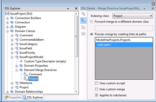
Figure 5-8 shows the menu for adding items to a project shape. If we remove the element merge directive under Project for Milestone, that item would disappear from the menu. You could still have a “Milestones” compartment in ProjectShape, but you would have to write custom code to link “Milestones” to Projects.
Figure 5-8. Add Item menu in a compartment shape is determined by compartments and EMDs
Add Menu in the Explorer
The language explorer provides a tree view of the model. Embedded elements can be added using the context menu in the explorer as long as there is also an element merge directive. Figure 5-9 shows the “Add” menu for a project. Notice that it can include every embedded item, irrespective of how it is represented on the diagram, so that both IssueCategory and IssuePriority are included. But in this example, the EMD for Milestone has been removed from the DSL definition, and so it does not appear on the menu—even though there is actually a Milestone in this instance of the model.
Figure 5-9. An Add command is generated in the explorer for each embedded item with an EMD

Multiple Link Creation Paths in an EMD
The user’s basic method of associating a Comment with a Project is to drag a Comment onto the diagram and then make a link from it to the Project (Figure 5-10).
Figure 5-10. Comment attached to Project

We have defined Comment to be embedded in the IssueProjectModel so that Comments can stand on the diagram on their own, if required. The connector between the comment shape and its subject (the dashed line in Figure 5-10) is mapped to a reference relationship between Comment and CommentableItem, of which Project is a subclass (Figure 5-11).
Figure 5-11. Comments and Projects

But suppose we want to provide an extra convenience for the user such as the ability to drag a Comment onto a Project and have the reference link made automatically. The EMD must create two links: the embedding in the IssueProjectModel and the reference to the Project.
Figure 5-12 shows the element merge directive we need. The index class is Comment and the EMD is owned by Project (because the user will drop the new comment onto a project). There are two link creation paths, both of which navigate from a project. The first creates the reference link from the project to the comment, specifying that we are creating a CommentReferencesSubjects link and adding it to the Comments property of the Project:
CommentReferencesSubjects.Comments
Figure 5-12. Element merge with multiple link creation paths
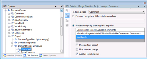
The second link directive creates the embedding link from the IssueProjectModel element to the Comment. But we’re starting at a Project, so first we have to get to the IssueProjectModel:
ModelHasProjects.Model/!Model/ModelHasComments.Comments
In a link directive, the last segment defines the link to be created; any preceding segments are about getting to the right starting point. In this case:
• ModelHasComments.Comments instantiates the ModelHasComments relationship, adding the link to the Comments property of the model.
• ModelHasProjects.Model/!Model navigates from the project to the model in two steps: first onto the link between the two, and then onto the model itself.
Forwarding
The “Forward merge” option in an EMD simply sends the element to be merged onto a different target.
For an example, let’s look at the Components sample that comes with the DSL Tools. In this model, each component can have a number of ports. On the diagram, each port appears as a box on the edge of its parent component’s shape.
New ports can be created by dragging the “Port” tool onto a component. There is an element merge directive in Component for which Port is the indexing class.
A typical component may have several ports (see Figure 5-13). When the user drags yet another port onto the component shape, it is easy to mistakenly try to drop the new port onto an existing port shape. From the user’s point of view, the ports are just part of the component. For the user’s convenience, we can arrange that an existing port will accept a new one but deals with it just by passing the new element on to the parent component. There, one of the component’s EMDs will process the new port. To set up the forwarding EMD on the Port class, we set its forwarding path to navigate from the Port element to its parent Component element:
ComponentHasPorts.Component/!Component
Figure 5-13. Component shape with ports
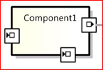
Notice that this path expression has two steps: from Port to the ComponentHasPorts link, and then on to the Component itself. (Without the second step, the forwarding would be to the intermediate link rather than the Component element.) A forwarding path can have several steps but must point to one specific element.
The target of a forwarding path must have an EMD that can deal with the class of element being forwarded. This is checked by the validation rules when you save your DSL definition.
Tip: Dangling bits when you delete a domain class
If you delete a domain class from the DSL, the old element merge directives and toolbox entries must be removed explicitly. Validation errors will point you to them.
Custom Element Merge Directives
Custom Accept
The “Uses custom accept” flag allows you to write code to have extra control over whether a merge can be done.
For example, if you want to prevent the user from adding more than five issue categories to any project, set the “Uses custom accept” flag in the EMD for IssueCategory under Project. This signals your intention to write some custom code. As usual, the best way to remind yourself of the name of the method you are expected to write is to click “Transform All Templates” and rebuild. This will give you the error that CanMergeIssueCategory() is undefined.
The generated class for the Project domain class, if you wish to look at it, will be in the GeneratedCode folder of the Dsl Visual Studio project, inside the DomainClasses.cs file, which you will find hiding under the DomainClasses.tt template.
Write a partial class for Project containing the missing method CanMergeIssueCategory(). The file will look like this:
using System;
using System.Collections.Generic;
using System.Text;
using Microsoft.VisualStudio.Modeling;
namespace CJKW.IssueProject
{
/// <summary>
/// Additional code for the class generated from the
/// Project domain class.
/// </summary>
public partial class Project
{
/// <summary>
/// This method must be provided because we have set the
/// Custom Accept flag in the Element Merge Directive
/// for the Project class.
/// Called by the Element Merge Directive to check whether a
/// given element may be merged into a Project instance.
/// </summary>
/// <param name="rootElement"></param>
/// <param name="elementGroupPrototype"></param>
/// <returns></returns>
private bool CanMergeIssueCategory
(ProtoElementBase rootElement,
ElementGroupPrototype elementGroupPrototype)
{
return this.Categories.Count < 5;
}
}
}
(The parameters are not very useful, because they merely identify the prototype from which the new element will be constructed: this has all the information we need.)
Tip: Custom accept code has to work fast
Custom accept code is called whenever the mouse passes over the boundary of a potential target of this type—so don’t have it doing something long and complicated.
Custom Merge
The “Uses custom merge” flag allows you to write code controlling how the merge is performed.
For example, we have already seen how an element merge directive can be designed to create and link a comment when the Comment tool is dropped onto a project; suppose we want to do the same for issue categories. Recall that the EMD has to create two links: a reference link from the comment to the target element and an embedding of the new comment into the model.
The embedding is more difficult, because it must first navigate from the drop target to the model. If the drop target is a Project, this just means navigating across the ModelHasProjects relation. But from IssueCategory, there is no fixed relationship to Model. An IssueCategory may be parented on other IssueCategories, and so there will be a variable number of steps up to the model. The path expression language does not include an iterative element.
Define an element merge directive under IssueCategory for Comment and set its “Uses custom merge” flag. In this case, you do not need to provide a path for link creation or forwarding. On transforming and building the code, you get errors that MergeRelateComment and MergeDisconnectComment are missing. Provide these in a partial class definition for IssueCategory:
using Microsoft.VisualStudio.Modeling;
namespace CJKW.IssueProject
{
public partial class IssueCategory
{
/// <summary>
/// The project that a category is ultimately parented by.
/// </summary>
public Project UltimateProject
{
get
{
if (this.Project == null)
return this.ParentCategory.Project;
else
return this.Project;
}
}
/// <summary>
/// Connect a Comment into the model.
/// </summary>
protected void MergeRelateComment(
ModelElement sourceElement, ElementGroup elementGroup)
{
Comment comment = sourceElement as Comment;
this.UltimateProject.Model.Comments.Add(comment);
this.Comments.Add(comment);
}
/// <summary>
/// Disconnect a Comment from the model
/// </summary>
protected void MergeDisconnectComment(ModelElement sourceElement)
{
Comment comment = sourceElement as Comment;
this.Comments.Remove(comment);
this.UltimateProject.Model.Comments.Remove(comment);
}
}
}
Tip: Take care with namespaces in folders
If the compiler persists in complaining that you have not supplied the required method, check both that you have its name correct and that the namespace in which you have declared it is correct. When you create a new file in a separate folder, Visual Studio creates a few lines of code for you, including a namespace that ends with the name of the folder: You need to delete that last part.
Re-Parenting with Element Merge Directives
In some cases, you need to move an element from one owner to another, breaking its old links with its owning context and reforming them with the new one. At the same time, we want to keep its other properties and links. In most cases, the link that has to be reformed is the single embedding link of which every element must be a target, but in some cases there may have been other links established by the element merge directive when the element was first created. For that reason, we can put an element merge directive into reverse, to do an “unmerge” or MergeDisconnect. Unmerging deletes those links that the EMD specifies (the same ones it normally creates). To move an element from one parent to another, first unmerge it from its existing context and then re-merge it into the new one.
An example occurs in the Task Flow example discussed in Chapter 4. Every FlowElement (task, start, stop, and so on) appears in the diagram on top of a swimlane, which represents an Actor (Figure 5-14).
Figure 5-14. Part of the Task Flow model. FlowElements are owned by Actors

When the user moves a FlowElement task1 from actor1 to actor2, the framework calls
actor1.MergeDisconnect(task1); actor2.MergeRelate(task1);
Custom Element Tool Prototypes
Each element tool is initialized with a prototype of the element(s) that are created when the user drags the tool onto the diagram. The standard generated code creates a single element as a prototype for each element tool, but you can define a group of interlinked elements. When the tool is used, the whole group will be replicated and merge attempted.
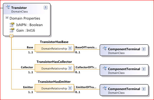
Consider a type of component diagram where some components must be created with a fixed set of ports. Electronic diagrams are typically like this. For example, a transistor always has three distinct terminals to which connections can be made (see Figure 5-15). (This example DSL could be used to generate code simulating the circuit or analyzing its properties.)
Figure 5-15. Transistors have three connections each

When the user drags a Transistor off the toolbox, we want a group of four elements to be created together: the transistor and its three component terminals, and the three links between them (see Figure 5-16). We therefore must override the initialization code that sets up the prototypes in the toolbox. This is in YourLanguageToolboxHelper, which is always double derived (that is, all its methods are in a separate base class).
Figure 5-16. A component that must be created with three subsidiary elements
using System;
using System.Collections.Generic;
using System.Text;
using Microsoft.VisualStudio.Modeling;
namespace Microsoft.Example.Circuits
{
public partial class CircuitsToolboxHelper
{
protected override ElementGroupPrototype
CreateElementToolPrototype(Store store, Guid domainClassId)
{
if (domainClassId == Transistor.DomainClassId)
{
// Set up the prototype elements and links.
Transistor transistor = new Transistor (store);
// Derived links must be set up in order of initialization
transistor.Base = new ComponentTerminal(store);
transistor.Collector = new ComponentTerminal(store);
transistor.Emitter = new ComponentTerminal(store);
transistor.Base.Name = "base";
transistor.Collector.Name = "collector";
transistor.Emitter.Name = "emitter";
// Create a prototype for the Toolbox.
ElementGroup elementGroup =
new ElementGroup(store.DefaultPartition);
elementGroup.AddGraph(transistor, true);
// Don't need to add children and links explicitly
// 'cos they're embedded.
return elementGroup.CreatePrototype();
}
// Code for other multi-element components goes here
else
{
// Default - single-element prototype - use generated code
return base.CreateElementToolPrototype(store, domainClassId);
}
}
}
}
This method is called once for each class on the toolbox when the DSL package is loaded. For classes that have standard single-element prototypes, we pass control to the base method. Where we want a multi-element prototype, we create an ElementGroup and construct a prototype from it.
Adding to an ElementGroup
You can add any number of elements and links to an ElementGroup. In this example, we have just included the embedding subtree (by using the AddGraph() method that does so automatically), but we could explicitly add other elements and reference links between elements in the same ElementGroup.
Instead of the AddGraph() method, you can use elementGroup.Add to add items individually to the group. AddGraph() automatically follows the embedding tree, while Add gives closer control.
Rather than writing out Add(transistor.Emitter); Add(transistor. Collector) and so on, this DSL has a common base relationship between all the components and their terminals, so that TransistorHasEmitter is derived from ComponentHasComponentTerminal (Figure 5-17), and all the Component subclasses have a property ComponentTerminals, which we can loop on:
Component component = element.ModelElement as Component;
elementGroup.Add(element.ModelElement);
elementGroup.MarkAsRoot(element.ModelElement);
foreach (ComponentTerminal terminal in component.ComponentTerminals)
{
elementGroup.Add(terminal);
}
Figure 5-17. Individual embeddings of ComponentTerminal are derived from ComponentHasTerminal.

Notice that we must mark the root element of the tree.
The Add() method has the curious property of also adding any relationship links that exist between the element being added and the elements already in the group.
At the beginning of this chapter, we said that there are two kinds of tools on the user’s toolbox: element tools and connection tools. We’ve now seen in detail how element tools create elements of a specific domain class and how they can be made to create groups of elements as well as how element merge directives control whether and how new elements can be merged into the existing model.
Connection Builders
The connection tools on the user’s toolbox work differently than the element tools. While an element tool creates elements of a specified class, a connection tool invokes a specific connection builder. This controls what elements the user may select to link and can generate a link of any of several different domain relationship classes, depending on the elements chosen. If you write custom code for it, you can make the user’s connect-this-to-that gesture initiate any actions you like.
The connection builder is invoked as soon as its connection tool is clicked by the user. (And of course you can also invoke a connection builder in custom code.) The connection builder governs what elements may be connected and exactly what links are made. Connection builders are listed at the top level of the DSL explorer.
When you map a reference relationship to a connector in the DSL designer, it automatically creates a connection builder for you (though you may then opt to change or delete it). The Issue Tracking example contains one such default (Figure 5-18). It has a single link connect directive specifying that a Comment may be connected to a CommentableItem element using the CommentReferencesSubjects relationship.
Figure 5-18. A connection builder

Notice once again the separation between diagrams and domain model. The connection builders deal only in domain relationships and their roleplayers. There is no mention of connectors or shapes. The connection builder creates a relationship, and then the connector mappings (which we saw in the previous chapter) do whatever is required, if anything, to display the relationship.
Multiple Source and Target Role Directives
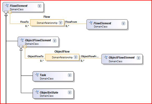
One connection builder can be used to instantiate several different relationships. Let’s look at the Task Flow example again (see Figure 5-19).

In this DSL several different types of element (Task, MergeBranch, StartPoint, and EndPoint) can be interconnected by Flow links. However, there are some restrictions; a StartPoint element cannot be the target of a Flow link, while an EndPoint element cannot be its source.
In the DSL definition (Figure 5-20), all the above classes are subclasses of FlowElement, and the Flow reference relationship is defined as linking any two FlowElements. When we map Flow to its connector, the DSL designer helpfully creates a generic connection builder that will allow any FlowElement to be connected to any other. But that’s not what we want in this case. For example, we don’t want an EndPoint to be an allowed source, and we don’t want a StartPoint to be an allowed target. So we list explicitly what we want to allow for the source and the target (Figure 5-21). (Of course, it only makes sense to list subclasses of the source and target roleplayers.)
Figure 5-20. General relationship Flow, between multiple element classes
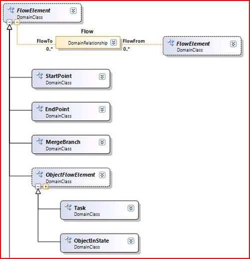
Figure 5-21. Connection builder listing restricted source and target sets

Tip: Adding a link connect directive
The user interface in the present version is slightly unintuitive. Scroll to the bottom of the list and click “<Add new>”; click the drop-down icon at the side and select the sole drop-down item—which also says “<Add new>”! This gives you a blank line. Now click on the blank domain class, and again click the drop-down icon. Usually it only makes sense to select the roleplayer class of that end of the relationship, or one of its derivatives—though this need not be the case if you write custom code to do some of the connect directive’s job.
Multiple Link Connect Directives
An additional feature of this DSL is a domain class called ObjectInState. An element of this class can be connected to and from tasks but using a different relationship, ObjectFlow (Figure 5-22). ObjectInState instances can also be interconnected with ObjectFlow links, but tasks may not be interconnected with ObjectFlow links. By careful definition of the connection builder, we can implement these restrictions while using the same connection tool as the flows between the other elements.
Figure 5-22. A second relationship, ObjectFlow
A new connection builder is automatically generated when we map the ObjectFlow relationship to its connector, but we can delete that. Instead, we add link connect directives to the existing Flow builder (Figure 5-23). This means that one tool can be used to create both types of relationship.
Figure 5-23. Additional link connect directives for the FlowBuilder connection builder

To summarize, we now have the following link connect directives all hanging off the Flow tool.
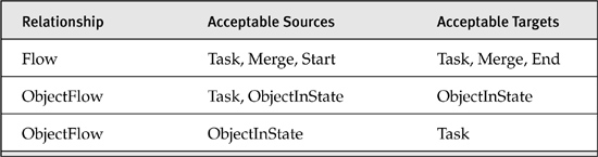
Where there are several sources and targets in the same link directive, they are not paired up; any combination of the listed sources and targets will work. However, the different link directives are separate; a user cannot connect an ObjectFlow from a task to a task.
Notice that after clicking the Flow tool, the user must click both a source and a target before it is clear whether a Flow or an ObjectFlow is to be created.
Sharing the one tool between several relationships is useful where they are similar; it reduces clutter on the toolbox and saves the user from remembering which tool to use. It is not recommended where the relationships are for different purposes—for example, connecting a comment to its subject should probably be a different tool.
Role Directive Path
A path can be specified for any source or target role in a link connect directive. This is to allow the user to click on one element while the link is actually made to another. The path navigates from the clicked element to the actual source or target.
Recalling the Components example, there is a relationship between Components called Generalization; the default connection builder lets the user drag from one component to another. But as we observed before, the user may naturally consider the ports around the edge to be part of a component, and therefore would expect to be able to drag to or from a port and have it work just the same as in the body of the component.
To allow this behavior, we define extra roles in the Link Connect Directive (Figure 5-24). The domain class listed is the one the user can click on; the path navigates from there to the actual start of the relationship being instantiated.
Figure 5-24. Link Connect Directive with Path to Roleplayer

Tip: Validate if you write custom connection builders
Connection builders and element merge directives govern only how the user creates relationships from the toolbox. They do not place continuing constraints on the relationships, and so any code you write can circumvent their restrictions. If you provide other ways for the users to create relationships, you might therefore want to write appropriate validation code (see Chapter 7).
Custom Connection Builders
Multiple degrees of code customization are available for connection builders. There are several “custom” checkboxes:
• “Custom accept.” Checking this box on a source or target role directive (see Figure 5-25) allows you to provide code that performs extra checks whenever the actual source or target belongs to that class.
• “Custom connect.” Checking this box on a source or target role directive allows you to provide code that creates the connection in the case where the specified source or target class is the reason for activating the link connect directive.
• “Uses custom connect.” This is the checkbox at the bottom of the connect directive (Figure 5-25); it also appears in the properties window when you select the link connect directive in the explorer. With this flag set, you provide code to deal with all cases when this link directive is activated.
• “Is Custom” property of each connection builder. This appears in the properties window when you select a connection builder in the DSL explorer. With this set, you provide code that takes over as soon as the user clicks the tool.
Let’s look at these in greater detail.
Figure 5-25. Custom accept on the target role

Custom Accept
Suppose we wish to prevent any comment (in, let’s say, the Issue Project example) from being linked to more than three subjects. Recall from way back in Figure 5-11 that the relationship is CommentReferencesSubjects, with source Comment and target CommentableItem (from which most of the other domain classes in that model are derived). So to connect a comment to a subject, the user will click on the “Comment Link” tool, then click a comment, and then drag from there to a suitable subject. To apply this constraint, we can determine whether the link is allowed as soon as the user clicks on the source comment, by counting the number of links the comment already has. So we set “Custom accept” on the Source Role (Figure 5-25) to get the designer to incorporate our code.
After clicking “Transform All Templates” and a rebuild, we get errors that CanAcceptCommentAsSource and CanAcceptCommentAndCommentable ItemAsSourceAndTarget are undefined. In a separate file, we define
/// <summary>
/// Called repeatedly as the mouse moves over candidate sources.
/// </summary>
/// <param name="candidate">The element presented by the shape
/// the mouse is currently hovering over.</param>
/// <returns>Whether this is an acceptable source.</returns>
private static bool CanAcceptCommentAsSource(Comment comment)
{
// Prohibit linking over 3 subjects to any comment using this directive.
return comment.Subjects.Count < 3;
}
As with the custom accept on a merge directive, this code has to work reasonably fast, responding to the mouse as it moves over the different elements.
After clicking the connection tool, the user moves the mouse over various shapes on the diagram. As it crosses each boundary, your CanAcceptXxxAsSource() method is called, and the mouse cursor shows an encouraging or discouraging icon depending on the Boolean value you return. If the user clicks on a shape for which you return true, then that element becomes the selected source, and the user then goes on to choose the target.
(Notice that, as usual, the method deals entirely in domain elements—there is no mention of shapes.)
You also need to provide code for CanAcceptXxxAsSourceAndTarget(), which is called when the user is choosing the second roleplayer. In the example we described, once the comment has been chosen, any subject is acceptable, so it can just return true. But suppose we wanted to impose the same sort of limit the other way around, so that each subject can have no more than five comments:
/// <summary>
/// Called repeatedly while hovering over candidate
/// second roleplayers.
/// The first has already been chosen and accepted.
/// </summary>
/// <param name="sourceComment">Comment to be linked</param>
/// <param name="targetCommentableItem">Subject to be linked</param>
/// <returns>Whether it's OK to link these two.</returns>
private static bool
CanAcceptCommentAndCommentableItemAsSourceAndTarget
(Comment sourceComment, CommentableItem targetCommentableItem)
{
return targetCommentableItem.Comments.Count < 5;
}
Notice that the ... AsSourceAndTarget() method is passed by both roleplayers of the candidate link, so it can be used to apply more interesting constraints that involve the two ends. For example, in the Components sample, there is a generalization relationship between components; the user should not be able to create loops in which a Component could be among its own ancestors. To achieve this, we set the “Custom accept” flag in either the source or target role in the Generalization link directive, and add code:
private static bool CanAcceptComponentAndComponentAsSourceAndTarget
(Component sourceComponent, Component targetComponent)
{
if (sourceComponent == targetComponent) return false;
if (targetComponent.Superclass == null) return true;
else return CanAcceptComponentAndComponentAsSourceAndTarget
(sourceComponent, targetComponent.Superclass);
}
There’s a slight variation on the above if you have set the “Reverses Direction” property of the connection tool (which appears in the properties window on selecting the tool in the explorer). This flag allows the user to drag in the opposite direction, from the target to the source. In that case, you need to set “Custom accept” on the target role directive (instead of the source) and provide a method for CanAcceptXxxAsTarget().
Notice that these custom methods only apply to the specific link directive for which you have set the “Custom accept” flag. The same connection builder may also be able to connect other combinations of elements with other directives.
Tip: Always set “Custom accept” on the source (unless you’ve reversed direction)
Should you set “Custom accept” on the source or the target of the link directive? You might think it depends on whether you want to write code that filters on the source or the target of the link, but in fact you can normally do either or both of those by setting “Custom accept” on the source. You only need to set it on the target if you have set the “Reverses Direction” flag on the connection tool that uses this connection builder.
“Custom accept” is an example of a hard constraint—that is, a constraint imposed by the user interface. The alternative is a soft constraint, which allows the user to create any number of comment-subject links but shows an error message when the file is saved. To do this, you would write a validation method (as described in Chapter 7) instead of the “Custom accept.”
However, as we remarked before, hard constraints only apply to a particular user operation, so if your customizations provide more than one method of creating this type of link, you must make sure that every method imposes the same constraint. For example, one of the variations above was designed to prevent more than a certain number of comments being linked to a single subject. Now suppose we have also implemented the neat element merge directive mentioned in the section “Multiple Link Creation Paths in an EMD” earlier in this chapter, in which you could create a comment and make a link to it at the same time just by dragging from the comment tool onto the required subject. In that case, the user can continue to connect up any number of new comments to one subject. The best approach to prevent this would be to add custom accept code to the merge directive, similar to what we’ve just written for the connect directive. (Just to be sure, we might also write a validation method to check the situation when the user saves the file.)
Custom Connect
Custom connect code is used to create a complex connection, for example, where the link is not between the source and target directly indicated by the user, but between some related items, or when there are actually several links to be created or perhaps some adjustment to be made to the properties of some of the elements.
If you set the “Custom connect” checkbox for a particular class in the “Connect Directive” details, then your code will be called just when the user’s first click was on an element of that domain class. (As before, you would choose to set it in the “Source role directives” tab or the “Target role directives” tab, depending on whether you have set “Reverses Direction” on the tool that uses this connection builder.)
If you set the “Uses custom connect” checkbox for a whole link directive (see the bottom left of Figure 5-25) then your code will be called if some combination of source and target was accepted.
Alternatively, you can set the “Is Custom” flag on the whole connection builder, to determine everything that happens when the user selects the associated tool.
A typical customized connect creates additional links or elements. In the Components sample, the user must create ports on the components before linking them (Figure 5-26). To save the user some time, we can create a port if necessary. The user can drag the connect tool either between existing ports or from or to the main body of a component. In the latter case, a new port is constructed, and the connection is made to that.
Figure 5-26. Components and ports

In this case, it is easiest to set the “Is Custom” flag on the whole connection builder. (Select the connection builder in the DSL explorer and set the flag in the properties window. As always, after modifying the DSL definition, click the “Transform All Templates” button to generate the code.) This generates a generic connection builder for which we have to provide three methods in a partial class.
using System;
using System.Collections.Generic;
using System.Text;
using Microsoft.VisualStudio.Modeling;
namespace CJKW.CJKWComponentModels
{
public static partial class ConnectionBuilder
{
///<summary>
/// Called to determine if we can drag from here.
///</summary>
internal static bool CanAcceptSource
(ModelElement sourceElement)
{
return sourceElement is Component
|| sourceElement is OutPort;
}
///<summary>
/// Called to determine if we can drag between these.
///</summary>
internal static bool CanAcceptSourceAndTarget
(ModelElement sourceElement, ModelElement targetElement)
{
return targetElement is Component
|| targetElement is InPort;
// CanAcceptSource already checked
}
///<summary>
/// Called to perform the connection.
///</summary>
internal static void Connect
(ModelElement sourceElement, ModelElement targetElement)
{
// Is the source a Component or a Port?
OutPort outPort = sourceElement as OutPort;
Component sourceComponent = sourceElement as Component;
if (sourceComponent != null)
{
// A component - so we need to create a source port
outPort = new OutPort(sourceComponent.Partition);
outPort.Component = sourceComponent;
}
// Is the target a Component or a Port?
InPort inPort = targetElement as InPort;
Component targetComponent = targetElement as Component;
if (targetComponent != null)
{
// a component - so we need to create a target Port
inPort = new InPort(targetComponent.Partition);
inPort.Component = targetComponent;
}
// make the connection between the two ports
outPort.Targets.Add(inPort);
// easy, eh?
}
}
}
Element Deletion
As the DSL is running in a designer or other application, instances can of course be both created and deleted. In a designer, the user can point to a shape or an element in the explorer and press delete, or code that you have written can call Remove() on the element. When an element is removed by any means, rules fire that seek to ensure the consistency of the store by removing any dependent elements.
One deletion rule is immutable: When any element is deleted, every link of which it is the source or target is deleted too. What happens next depends on the delete propagation rules for the links. Separate delete rules can be defined for each relationship. There is a default set of rules, so you only have to think about them when you want something special to happen.
Default Delete Propagation Rules
There are some default rules, but you can change them or add others.
• If the link belongs to an embedding relationship, then its target is also deleted. So deleting any element deletes its entire embedding subtree.
• The source of an embedding relationship is not deleted by default. If you want deleting a child to delete its parent automatically, you must add a delete propagation rule to the parenthood relationship.
• Deleting a reference link affects neither of its roleplayers.
For example, if you select the Component domain class in the Components sample and then click on the “Delete Behavior” tab of the DSL details window (Figure 5-27), you can see all of the domain relationships listed in which this class takes part. In fact, there is an entry for each role that the domain class plays, so that reflexive relationships like Generalization appear twice.
Figure 5-27. Delete Behavior tab in the DSL Details window for the Component domain class
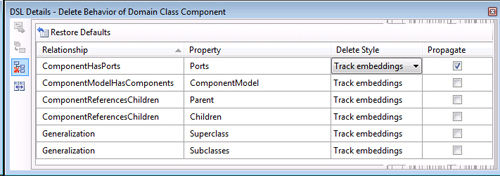
The Delete Style column indicates either “Track embeddings” or “User specified.” “Track embeddings” means that the “Propagate” box is checked if this is the source of an embedding relationship, and unchecked otherwise.
It is mostly easy to test delete propagation. Set “Propagate” on the Subclasses property of Generalization, for example; click “Transform All Templates,” build, and run; and draw some components and several generalization connectors between them. When you delete one component, you will see its subclasses in your diagram vanish too, along with all their subclasses. And of course any ports on the components also vanish because of the default setting of “Propagate” on the embedding relationship, ComponentHasPorts.
Tip: Take care when disabling default delete propagation
Disabling propagation at the source of an embedding relationship means that if a parent instance is deleted (a component in this case), then any children (ports) are left lying around in the store without being in the embedding tree. This is a situation of dubious value, because displaying, serialization, and validation all depend on everything being in the tree. It is generally not wise to disable propagation on embedding relationships unless you have some custom code that will reassign the element to another part of the tree.
The effect of unchecking the “Propagate” flag on the source of an embedding relationship is less easy to detect. In this example, it still looks as though deleting a component appears to delete its ports—together with any connectors attached to them. However, the port shapes vanish because the view fixup rules (which implement the shape map) work down the tree and fail to find the associated model element. Removing the port shapes in turn removes their attached connectors from the diagram, because there is delete propagation from shapes to connectors.
Controlling Delete Propagation
In the Circuit Diagrams sample that we introduced earlier (Figure 5-15), each class of component is supposed to have a fixed set of ports—all transistors have three connections, all diodes two, and so on. But if the user selects any individual port and presses the delete key, the port will duly disappear. One way of avoiding this embarrassing inconsistency is to provide the convenient feature that deleting the port will delete the whole thing. This allows the user to click on the port—perhaps mistakenly intending to click its parent component—and still achieve the desired deletion. To make this happen, we first select the ComponentTerminal domain class and open the delete behavior tab in the DSL Details window. There are a lot of entries, because a component terminal can be attached to any of a number of different components by several relationships each. (See the model in Figure 5-17.) In fact, there is an abstract relationship from which all these are derived, and it would be nice if we could just check its box (ComponentHasComponentTerminal); in the current version of the DSL Tools, that doesn’t happen, so we have to go through and check all of the boxes (Figure 5-28).
Figure 5-28. Delete Behavior tab for ComponentTerminal in the Circuit Diagrams sample

After clicking “Transform All Templates” and rebuilding, deleting any port now deletes the parent component and its other ports.
Delete Propagation and Constraints
Delete propagation is generally used to help enforce a hard constraint. For example, in the Task Flows sample, each instance of the ObjectInState domain class (see Figure 5-22) should always have one link to a source and one to a target task. Therefore, if a task is deleted, we want any linked ObjectInState instances to vanish too.
Once again, this feature does not guarantee a constraint by itself; you might in the same DSL provide the means for the user to create an unlinked ObjectInState element. To make sure a constraint is observed, you have to consider all the methods of creation and deletion that the user can access or that your custom code provides.
Customizing Delete Propagation
If you want more complex behavior, you can override parts of the XXXDeleteClosure class, which is generated from the Delete Behavior definition (where XXX is the name of your DSL). You will find the generated class in DomainModel.cs in the GeneratedCode folder of the Dsl project. There is only one class whose name ends with “DeleteClosure.”
The ShouldVisitRolePlayer() method of this class is called every time any link is to be deleted, and its job is to decide whether each roleplayer (that is, the instance at the end of the link) should be deleted too. The default method just looks at the delete propagation flags in the DSL definition. But to get more dynamic behavior, we can override it. Because it is called for every link that is deleted, we must be careful to pass back control to the base method in the cases where we aren’t interested in customizing the behavior.
For example, you might want to delete a Component element when, and only when, the last of its child ports have gone. To do this, you can write the following custom code.
// Replace "Components" in this class name with the name of your DSL.
public partial class ComponentsDeleteClosure
{
/// <summary>
/// Called when deleting a link, to decide whether to delete a
/// roleplayer.
/// </summary>
public override VisitorFilterResult ShouldVisitRolePlayer
(ElementWalker walker, ModelElement sourceElement,
ElementLink elementLink, DomainRoleInfo targetDomainRole,
ModelElement targetElement)
{
ComponentHasPorts portParentLink =
elementLink as ComponentHasPorts;
if (portParentLink != null)
{
// Delete if there is just one left in the *old* state.
if (portParentLink.Component.Ports.Count == 1)
return VisitorFilterResult.Yes;
else
return VisitorFilterResult.DoNotCare;
}
else
return base.ShouldVisitRolePlayer(walker, sourceElement,
elementLink, targetDomainRole, targetElement);
}
}
Tip: Customization with overrides
This customization is done just by overriding a method from the generated code. Unlike the previous examples in this chapter, it doesn’t require you to set any “custom” flag in the DSL definition. Unlike the custom flags technique, it isn’t always obvious what methods are good to override. We discuss more of them in the rest of this book, but you can always experiment. Write a partial class definition for any of the classes that occur in the generated code and type “override” within it. IntelliSense will give you a range of methods you can try overriding. Inefficient but fun.
The base method (which this one overrides) is called when any deletion is made to any element. There is just one such method in the DSL code (rather than, for example, one for each domain class). The method is called whenever a link is about to be deleted. The most useful parameters are elementLink, the link which is about to be deleted, and sourceElement and targetElement, the items at its two ends. Recall from Chapter 3 that the classes ElementLink and ModelElement are the ancestor classes of all domain relationship instances and all domain class instances.
The first thing we do is to try to cast the elementLink to the domain relationship class that we are interested in. This method will be called when any link is deleted, but we are only interested in the ComponentHasPorts relationship. If it isn’t one of those, we just pass control back to the base method.
If this is indeed a link between components and ports, we can go ahead and decide whether the target should be deleted on the basis of our own requirements—in the case of this particular example, by counting the ports that the component still has. (Because this method is called before any changes are made, the condition we want is that there is just one port left—not zero!) This logic replaces the check to see whether the appropriate PropagateDelete flag is set in the DSL definition, which is what the base method would do.
The VisitorFilterResult values that we can return are
• Yes: The roleplayer should be deleted.
• Never: The roleplayer should not be deleted in this transaction.
• DoNotCare: The roleplayer should not be deleted, according to this rule. However, if another link targeting the same element causes its deletion, then that is OK.
Summary
The main points made in this chapter were
• An element tool creates an instance of a specified domain class. You can customize it to create a group of instances, though there is always one principal element in such a group.
• As the user drags from an element tool onto the diagram or onto existing elements, the element merge directives of those elements (the root element, in the case of the diagram) determine whether the prototype from the tool is acceptable to be merged. By default, the decision is made on the basis of classes, but you can write custom code to define more complex criteria.
• When an element tool is dropped onto the diagram or existing elements, a merge happens under the control of the element merge directive, which creates one or more links between existing and new elements. You can write code to handle more complex merge schemes.
• When the user clicks a connect tool, the associated connection builder is activated. This determines what elements may be linked together and what domain relationships will be instantiated to link them. In the DSL definition, you can specify which combinations of domain classes cause links of different domain relationships to be created. By writing custom code, you can make more complex choice schemes and create more than one link at a time.
• When an element is deleted, its neighboring links are deleted, too; they in turn may cause their other roleplayers to be deleted. Delete propagation is controlled by the DSL’s DeleteClosure class, which normally uses the “Propagate” flags you have set in the DSL definition but whose code can be overridden to define more complex behavior.