LINEAR PERSPECTIVE
Previously we have discussed the picture plane, eye level, “table-top” perspective, and perspective terminology, giving us a basic understanding of one- and two-point perspective. In this final chapter, we will go into more depth on perspective as it relates to observation and drawing architecture—both interior and exterior. Understanding perspective theory—and how to apply it—will help you create strong, accurate spatial drawings.

Principles of Perspective
For centuries prior to the Renaissance, artists struggled to portray the world around them with an accurate depiction of spatial dimensions, usually with little or no success. Just before the Renaissance, several artists (among them, Andrea Mantegna and Tommaso Masaccio) discovered clues to solving the mystery of where lines and edges converge in a depiction of deep spatial dimension. The main discovery was the vanishing point and the theory behind it, which states that lines and planes converge to a point or points on the artist’s eye level, based on the artist’s viewpoint.

To truly understand the logic of perspective, you need to start with eye level. Eye level and the horizon line are one and the same. Eye level is the viewer’s perspective—the way things appear at the viewer’s level of observation. If the viewer changes his or her height by climbing up a staircase or sitting on the floor, the perspective view changes as well. Eye level is always horizontal, never at an angle. Note: Eye level/horizon line is portrayed as a horizontal red line here and in all further illustrated examples.

Foreshortening As planes of the same size move away from the viewer, they become narrower and flatten as they recede.

Vanishing Points Lines or planes recede into in the distance to a mutual point(s). Vanishing points are always on the horizon line (eye level).

Convergence Lines or planes that are parallel to each other appear to converge, or come together, as they move away from the viewer.

Size Diminishment The posts and beams diminish in scale proportionally, as there is equal distance between each set.
Understanding the key relationship between eye level, also called the horizon line, and the vanishing point is crucial. Vanishing points are always on eye level. Later in this chapter we will discuss different types of convergence points, but true vanishing points are always on the horizon line. Vanishing points may not always be directly in front of the viewer, as is the case in a two-point perspective situation. Even so, always know that the angled edges of parallel and perpendicular planes (walls) are converging on perspective vanishing points that are always on the viewer’s eye level.
Eye Level
Understanding where eye level falls is a key component to drawing in perspective. When observing and drawing an architectural subject, always know initially where true eye level falls. The example below is of a very low eye level; the artist is sitting and drawing from the ground. Even if you’re not sure exactly where the vanishing points are located, you can assume that they are on eye level.

When the eye level is elevated, as demonstrated above, notice what happens to the angles on the rooflines, windows, and sidewalks. Once an artist understands the importance of eye level location, it’s easy to spot inaccuracy in a drawing. Remember not to confuse line of vision with eye level. You can move your eyes up and down to see objects, but the true eye level stays constant.

Illustrated here is a normal eye level for most people. The sidewalks widen dramatically as they advance toward the viewer. The tops of doors and windows converge down toward the vanishing point on eye level; the higher the windows and rooflines, the more acute the angles become.

Here is the same view from several floors up. The eye level has changed and so has the perspective view. The sidewalk edges closest to the viewer are narrower and less foreshortened. Most of the window tops and bottoms on the building to the right are below eye level, so their edges converge up to the vanishing point on eye level.
The Picture Plane
As discussed here, the picture plane is an imaginary sheet of glass between the viewer and the subject. It is meant to represent your drawing board, and the viewer’s line of vision should extend through it at a right angle. The picture plane, in theory, is facing exactly what you are drawing, which encompasses roughly a 60˚ circle around the viewer, which is called the cone of vision. If you find yourself turning your head to see what is on one side within that zone, you are basically turning your picture plane and your cone of vision, and there will be distortion in your drawing.

This is a one-point perspective situation. The back wall, or plane, of the far building is parallel to the picture plane. The vanishing point is directly in front of the viewer. The one-point perspective is apparent on the building to the right, which is perpendicular to the far building that is parallel to the picture plane. The tops and bottoms of this far building are horizontal, parallel to eye level.
One-Point & Two-Point Perspectives
If the wall or plane in the background of your view is parallel to the picture plane, or if the building that you are drawing is perpendicular to the picture plane, it is a one-point perspective situation. In this situation, the edges of the walls are parallel and vertical to the picture plane, and the top and bottom edges of the floor and roofing are horizontal.

Here is a classic one-point situation, with the back wall and arched opening parallel to the picture plane and the walls on both sides perpendicular to the back wall. Student perspective drawing by Jane James. Time: 8–10 hours.

This is also a one-point drawing, but the eye level is very elevated; the artist is sitting on a staircase somewhere around the second floor. To understand and portray this perspective, the artist must focus on a point directly in front of him or her on true eye level; otherwise, the drawing will not be accurate.
In two-point perspective, neither wall of a building is parallel or perpendicular to the picture plane. Lines, planes, and edges on each side converge to common vanishing points on their perspective sides. The only edges that are horizontal within this view are lines or edges that coincide with the horizon line. In order to accurately portray the correct proportions of a building in two-point perspective, it may be that one or both vanishing points for the building are located beyond the limit of the paper.

The main difference between one- and two-point perspective is that, in a two-point view, none of the planes (or walls) of the building are parallel to the picture plane. Think of this building as a large box that is tilted away from the picture plane. The edges of the walls on the right (green lines) converge to a vanishing point on the same side on eye level. The edges of the walls on the left (blue lines) converge to a vanishing point on the left side, also on eye level.

Here is what the line drawing of the building would look like to the artist looking through the picture plane. Notice the angles of the receding lines as they move away from horizontal (eye level). As the lines rise away from each other, there is a gradual change in the angles, culminating in the steepest angle at the top-most point of the building. Notice also that eye level is the same for all three people depicted in the image. The figures become proportionally smaller as they move further from the picture plane, but on a flat surface like this, their eye levels stay the same.

This illustration demonstrates where the vanishing points actually are for this two-point perspective drawing. In most two-point drawings, vanishing points fall off the page if they are drawn accurately.
Drawing Interior Perspectives
Drawing an interior perspective can be described simply as drawing the inside of a box, rather than the outside; all the same principles still pertain, with a few subtle differences.

A one-point interior: Remember that the picture plane is parallel to the back wall facing the artist, and we can see that all of the lines on the perpendicular walls converge directly to one vanishing point on eye level. Student perspective drawing by Stephanie De Roo. Time: 4–5 hours.
First establish whether the view is a one-point or two-point perspective situation. If the back wall facing you is parallel to the picture plane, it is a one-point perspective. If none of the walls within your view are parallel to the picture plane, it is a two-point perspective. Always remember to find the eye level right away; if it is a one-point perspective, the vanishing point for the perpendicular walls will be directly in front of you.
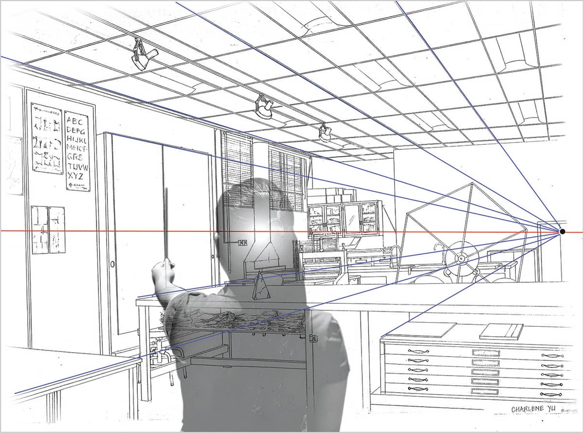
A two-point interior: The picture plane (and the artist) have turned away from the back wall; the picture plane is now parallel to the corner of the room, and the artist’s line of vision is directed at the corner of the room. The blue lines on the left wall, as well as any structural edges on or parallel to that wall, all converge to a common vanishing point on the right side of the drawing. Student perspective drawing by Charlene Yu.

The right-side wall and all structures parallel to it are represented as green lines that converge to a common vanishing point to the left side of the drawing. Again, look at the angles presented by the lines above and below eye level as they move away from horizontal. Student perspective drawing by Charlene Yu.
In the two-point perspective demonstrated above, you can see that the vanishing point for the left wall is within the picture plane, but the vanishing point for the right wall is well outside of the picture plane. In a two-point perspective drawing, it’s a good idea to expect that neither vanishing point will be on the paper; but it’s always a nice surprise when one of them is.
Two-Point Perspective Construction Demonstration
Creating a perspective drawing from observation is a logical process that involves understanding the picture plane and how it is used, transferring accurate sight-size measurements of the subject to the drawing, and being able to accurately see and draw angles in perspective—even if there are no vanishing points within the drawing.
Remember the all-important rule when sight-size measuring. Your arm must always be straight when measuring for consistent proportional measurements. Follow along with the demonstrated steps as you work on your own drawing.

USING A CHOPSTICK for angles and exact measurements, we will make extensive use of the picture plane and follow a logical, step-by-step progression to achieve an accurate interpretation of the building.

STEP 1 Start with a thumbnail sketch. This is a helpful reference throughout the drawing process, and it provides the artist with more knowledge of the subject before beginning the main drawing. Try using a red pencil for eye level, both on the thumbnail sketch and the main drawing. Thumbnail sketches should always be done freehand, without rulers or measuring, in about 15 minutes.

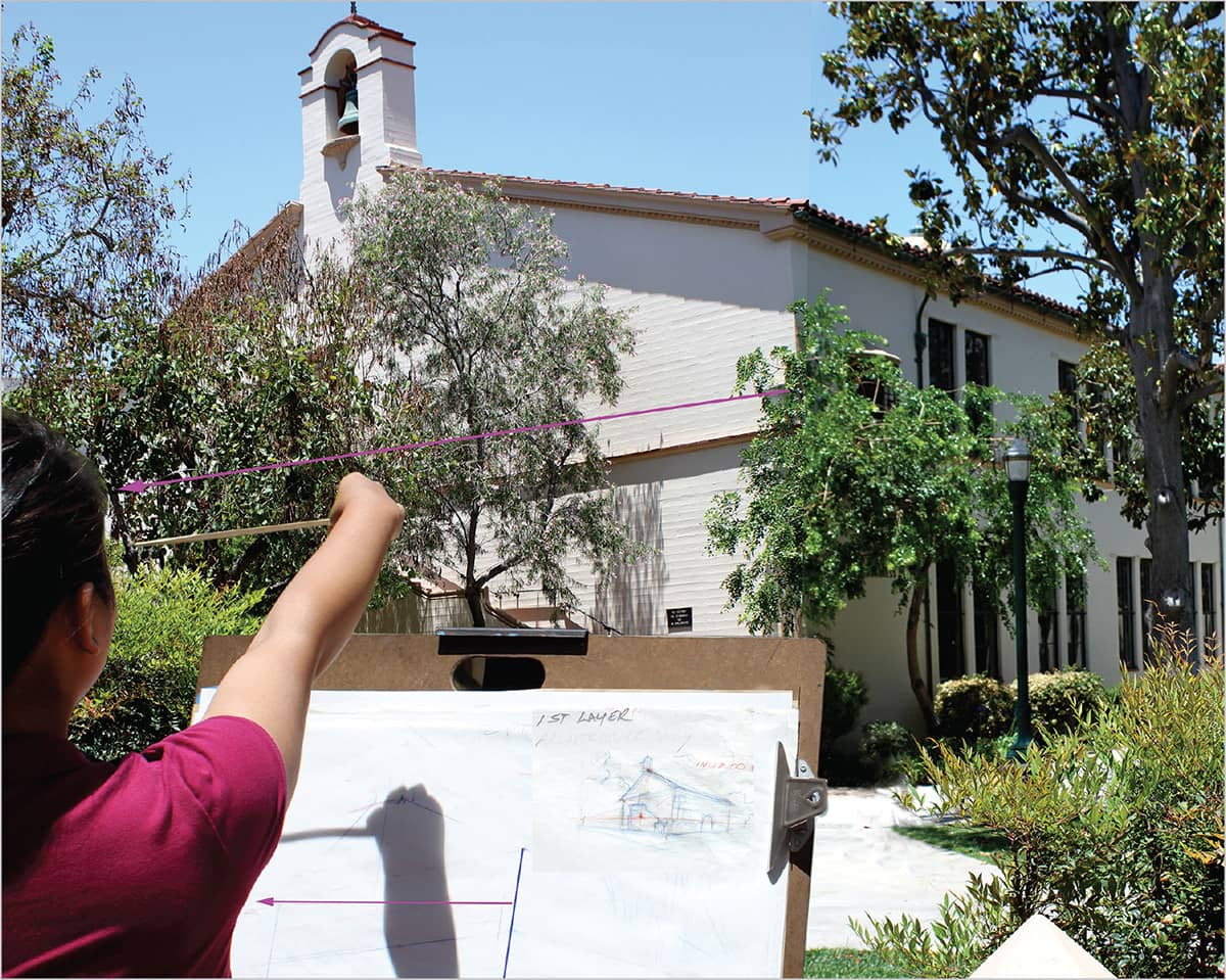
STEP 2 Once eye level is identified, determine its placement on the paper. (It's usually about a quarter of the way up from the bottom of the page, as there is more architecture above eye level than below it.) Use actual sight-size measuring, meaning the actual size you measure with a chopstick on the building is the same measurement you put on the paper. Start with a measurement on the corner of the building closest to you; measure from eye level up to the top corner of the building (purple arrow) and then from eye level down to the bottom corner. Apply the exact measurement of the front corner of the building from eye level to the roofline to the drawing. Sight-size measuring is a very easy and logical way to obtain accurate measurements and angles for this type of drawing.

STEP 3 Use a chopstick to quickly check measurements and mark your paper, and use a ruler to achieve accurate sketched lines.
STEP 4 The next step is to ascertain the width of the front face of the building. Use the edge of the drawing board as a consistent location for your hand with the chopstick as you keep your arm straight.

STEP 5 Apply the same measurement of the width of the front of the building to the drawing. Make a mark on the page where the location of the far corner of the building will be. When using the chopstick for angles and measurements, it is a good idea to use your nondrawing hand, as it is much easier to measure and make marks at the same time, without changing hands. Draw in the far corner, above and below eye level before moving on.
Note: The finished sketch is “ghosted” onto this image to more easily demonstrate the action.

STEP 6 Now it’s time to add the right side of the building. Start with the end of the chopstick on the nearest corner, which has already been drawn, and measure to the far end of the building.

STEP 7 Establish the length of the building and mark your paper. Measure the height of the building’s end above and then below eye level. Remember this step; if you only measure the entire height of the wall, including both above and below eye level, you can’t be certain where to locate eye level on the line.

STEP 8 Mark the paper; now both sides of the building are established.

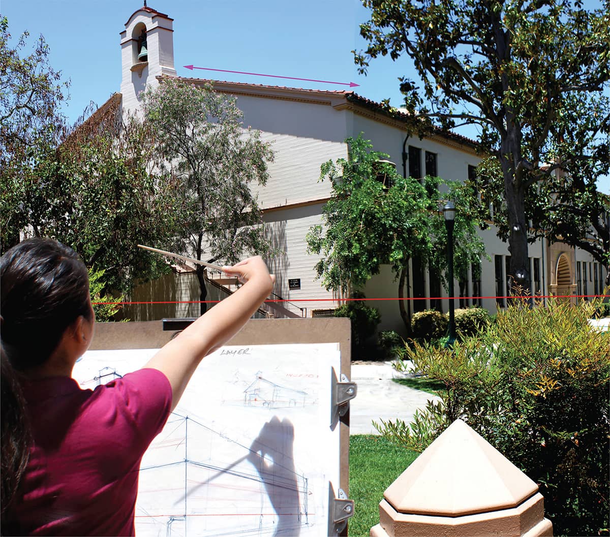
STEP 9 In order to ascertain the pitch of the roof, measure laterally from the nearest corner of the building to the vertical-axis location of the roof. You can then establish the height of the roof in that lateral location from eye level.

STEP 10 Once the rooflines are established, the bell tower can be constructed by finding the midline of the structure. Extend lines from each corner of the vertical edges that establish the height of the walls; those lines form an “X” (shown here in green), dividing the wall into perspective halves. The middle of the “X” is the location of the midline of the structure. At this point, a vertical measurement with the chopstick from eye level will locate the top of the building.
STEP 11 Check the roof angle with the chopstick.

STEP 12 After all of the measurements are finished on the first layer, add a second layer of tracing paper to refine the freehand sketch, finishing the windows, doors, trees, sidewalks, and building details.

The final ink perspective drawing. Time: 6–8 hours.
Inclined Planes
Inclined planes are parallel-edged planes that are neither horizontal nor vertical to the picture plane, but rather, they are angled to it. Examples of inclined planes include staircases, elevated ramps, and angled rooftops.
These parallel-edged planes have their own point of convergence, called a trace point. These trace points rise either above or below eye level, depending on the direction that the inclined plane slants away from the picture plane. One of the rules that governs inclined planes is that parallel edges that incline away from a set of parallel and perpendicular planes (that are parallel to the picture plane) converge to a trace point that is directly vertical to the vanishing point on that side.

Inclined planes are angled structures, such as stairways and rooflines, that don’t follow the same perspective rules as structural walls parallel to the picture plane. However, they do have their own set of rules and logic. One rule seen here is that the parallel edges of the inclined plane (in this case, a staircase) converge to a trace point directly above the vanishing point.

In this example we can see that when a rooftop is angled away from the picture plane, the parallel edges of that roof converge to a trace point directly above the vanishing point for the buildings, which is always on eye level.
Aerial Perspective
The rules for this type of perspective were also discovered during the Renaissance (usually attributed to Leonardo da Vinci) and state that as objects move away from the viewer, they become softer and lighter in color and value. Da Vinci called this phenomenon the perspective of disappearance. We know now that as the distance of an object increases, more and more atmosphere comes between the viewer and the object, causing the distant object or structure to appear bluish in color.

Aerial, or atmospheric, perspective occurs as objects that are the same in color and value become muted as they move away from the viewer. As the distance of an object increases, it becomes somewhat softer and less distinct because of the atmosphere that comes between it and the viewer; the greater the distance, the greater the reduction in contrast and detail. This explains why mountains in the distance appear bluish during daylight hours. An artist can suggest atmospheric perspective by varying the line weight from the back to the front, with lighter receding lines and darker approaching lines. This same theory works with value in tonal drawings, as well as changes in value and intensity in color drawing and painting.
YOUR HOMEWORK
Create a one- or two-point perspective drawing from observation anywhere in your home. The larger and more interesting the space the better, although I have seen some very good bathroom drawings!
Start with a small thumbnail sketch of the space, understanding from the outset where your eye level is within the room, if it will be a one-point perspective drawing, and where the vanishing point is.
Sketch lightly at first, using a pencil or chopstick for measuring and angles, and refine your final drawing with the surrounding details of the room, such as houseplants, bookcases, paintings and photographs, lamps, etc.

Employing Aerial Perspective and Shadows
In nature, impurities in the air (such as moisture and dust) block out some rays of sunlight, making objects in the distance appear less distinct than objects in the foreground. This phenomenon is referred to as “aerial perspective,” and it creates the illusion of depth. This quiet scene takes advantage of aerial perspective, and foreground shadows give the drawing dimension.

CHOOSING A SCENE This location is more interesting in the summer when long shadows come from the side, but this photo was shot in winter with the sun coming in from the south. The solution? Simply shift the direction of the shadows by modifying the composition to match the summer memory. Despite the limitations of the photo, you still can use it to reference when building an appealing composition.

THUMBNAIL SKETCH Before starting the actual rendering, draw a thumbnail sketch. After blocking in the basic shapes, lay in the new, summer shadow areas. The intention is to lead the viewer’s eye into the scene by establishing dark, contrasting shadows across the foreground. This thumbnail is now a value guide; the photo is only a reference for the shapes and details.

ROUGH VALUE STUDY Now shade in the three main values you intend to use: The tree is the darkest value, the shadows and background are middle values, and the rest is light. This is not a final, detailed value study—just a rough guide to recognize the light and dark families as you proceed toward the final rendering shown here.

STEP 1 Using an HB pencil, lightly block in the general composition, paying special attention to the perspective on the benches, table, and barrels. These shapes, if drawn correctly, will give an indication of the artist’s eye level, which is slightly above them.

STEP 2 Now further refine the shapes and begin to lay in darker values with underhand strokes. Don’t get as dark as the value study yet to be sure that the shapes of the foreground shadows are placed correctly.

STEP 3 At this point, take out your softer 2B and 4B pencils and carefully refine the areas of value. Now the darkest shadows are about as dark as the value study, and now you can focus on adding textures while maintaining the correct values.

STEP 4 At this stage, begin to experiment with various textures, but do not completely finish any particular area. Add details such as palm trees in the background, the gradated sky, and the dark windows and doorways.

ADDING TEXTURES Use these strokes to finish the drawing: darken the tree with 4B and 6B pencils, combining sidestrokes and cross-hatching (A). For the sky, combine sidestrokes, linear strokes, and some erasing to lift out lighter streaks (B). For the background, use sidestrokes and an eraser (C). For the grassy area in the foreground, use sidestrokes and grassy strokes (D). Darken the barrel with sidestrokes and linear, vertical strokes (E). The dirt is—appropriately—dirt texture (F).

STEP 5 Complete the drawing by adding value and texture. The addition of larger figures in the middle ground and smaller figures in the background helps create depth. Note how to employ aerial perspective by giving the objects in the foreground the most detail. The darker foreground shadows add to the illusion of depth by contrasting the lighter middle ground and background.