
Detailed Description of LRH
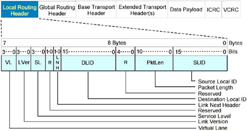
Refer to Figure 25-3 on this page. The LRH is the first field in every data packet and is required. It consists of the sub-fields shown in the illustration. The sections that follow provide a description of each subfield within the LRH.
Figure 25-3. Local Route Header
SL and VL Fields
These two LRH fields are each 4 bits wide.
SL Indicates Desired QoS and Is Specified by Software
The Service Level (SL) defines the desired QoS for a message's transit through the local subnet from the source CA port to the destination port within the same subnet. Software obtains the SL to be used for a given source/destination port pair from the SA (specifically, from a PathRecord; see “PathRecord” on page 975). The SL is then specified for each of the IBA service types in the following manner:
RC and UC. Software specifies the desired QoS when it initially sets up a RC or UC QP within a CA. The SL is stored in the QP's Context and is used in all message transfer request packets generated by the QP's SQ.
RD. Software specifies the desired QoS when it initially sets up a local and remote EEC within two CAs. The SL is stored in the EEC and is used in all message transfer request packets generated by the EEC's Send Logic.
UD. Prior to posting any message send requests to an UD QP's SQ, software must use the Create Address Handle verb to create Address Handles to be associated with each remote port to which messages destined for UD QPs behind those ports will be sent. Software supplies the SL it wishes to associate with the path to the destination remote port as one of the verb's input parameters. Then, when posting a message send request to the local UD QP's SQ, software identifies the destination remote port by specifying its Address Handle. Software also specifies the QPN of the destination UD QP in the WR. The local UD QP's SQ Logic then obtains the SL from the Address Handle (as well as other information related to the destination port, such as its LID address, etc.).
Raw. The SL value to be inserted in a raw request packet is specified in the WR posted to the raw QP's SQ.
SL Is Included in Packets and Doesn't Change in the Subnet
Each packet associated with a particular message includes the SL (in the LRH). The SL field is not altered as the message's packets make their way from the source port to the destination port within the local subnet. Note that a router may choose to alter the SL (i.e., the desired local QoS) to be used when the packet is injected into the next subnet.
VL Is Derived from SL
The originating port's Link Layer uses the SL field value to choose which of its Link Layer's VL transmit buffers to use in transmitting the packets associated with the message. Likewise, the Link Layer in each switch that the packet transits each use the SL field in the packet to determine which VL transmit buffer in the egress port to use to retransmit the packets. Refer to “QoS within the Subnet: SL and VLs” on page 617 for a detailed discussion of the VL concept (including the relationship of the SL and VLs).
VL Field
The 4-bit Virtual Lane (VL) field in a packet's LRH identifies:
From which of the transmitting port's Link Layer VL transmit buffers the packet is being transmitted, and
Into which of the receiving port's Link Layer VL receive buffers the packet is to be accepted.
It should be noted that the VL can change as the packet travels through switches from link to link in the local subnet. Since the VL can change, this field is not included in the calculation of the packet's Invariant CRC (ICRC) field.
LVer Field
The 4-bit LVer field specifies the version of the LRH used in this packet. The version applies to the general packet structure including the LRH fields and the variant CRC (VCRC). The only valid LVer field value currently defined is zero.
If a receiving device does not support the specified link version, the packet is discarded.
LNH Field
The 2-bit Link Next Header (LNH) field identifies what header immediate follows the packet's LRH field. Refer to Table 25-1 on page 613. The most-significant bit indicates whether the packet is an IBA packet (i.e., it's an IBA local or global packet), or a non-IBA packet (i.e., it's a raw IPv6 or raw EtherType packet) while the least-significant bit indicates one of the following:
If the msb = 1, the lsb indicates whether it's an IBA local or global packet.
If the msb = 0, the lsb indicates whether it's a raw IPv6 or a raw Ether Type packet.
| Packet Type | Bit 1 IBA Transport | Bit 0 GRH/IPv6 Header | Transport Type | Header(s) following LRH |
|---|---|---|---|---|
| IBA Global | 1 | 1 | IBA | GRH followed by BTH (Base Transport Header). |
| IBA Local | 1 | 0 | IBA | BTH. |
| Raw IPv6 | 0 | 1 | Raw | IPv6 Routing Header followed by possible additional transport headers, followed by the data payload. |
| Raw EtherType | 0 | 0 | Raw | RWH (Raw header containing the EtherType field) followed by possible additional transport headers, followed by the data payload. |
DLID Field
The 16-bit DLID field specifies the LID of the destination port within this subnet. It can be any of the following:
The LID of the actual destination CA port if the port is in this subnet.
The Permissive LID address (FFFFh), if the destination port does not yet have a LID assigned.
The LID of an ingress port on a router in this subnet that is in the path to the ultimate destination CA port.
Each switch Link Layer performs a lookup in its Forwarding Table to determine which of its output ports to transmit the packet through.
SLID Field
The 16-bit LRH:SLID field identifies the port which injected the packet into this subnet. It is set to one of the following values:
If the requester CA port that originated the packet is in this subnet, then the LRH:SLID = the LID of that CA port.
If the requester port that originated the packet is not in this subnet, then the LRH:SLID = the LID of the router port that injected the packet into this subnet.
If the packet is a directed-route SMP (refer to “Solution: Directed-Route SMP” on page 875 for a detailed discussion of directed route SMPs), the SLID is set to one of the following:
Packet Length Field (PktLen)
Description
This 11-bit field specifies the number of dwords (32-bit data items; referred to as a dword in the Intel world and as a word in many RISC environments) contained in the packet.
It is set to the number of bytes in all packet fields:
starting with the first byte of the Local Route Header
up to and including the last byte before the Variant CRC (VCRC)
÷ 4.
MTUCap and NeighborMTU
The amount of data that may be transmitted in a packet's data payload field (see Figure 25-3 on page 610) is defined by the capabilities of the two ports attached to either end of the link (i.e., the transmitting port at one end of the link and the receiving port at the other end). Each port implements the following two attributes:
PortInfo.MTUCap (Maximum Transfer Unit Capacity) is a read-only, 4-bit attribute indicating the largest packet payload that the port's transmit and receive buffers can handle.
- 1h = 256 bytes.
- 2h = 512 bytes.
- 3h = 1024 bytes.
- 4h = 2048 bytes.
- 5h = 4096 bytes.
- 6h-Fh are reserved.
PortInfo.NeighborMTU is a read-write, 4-bit attribute indicating the maximum size packet data payload that be transmitted from this port to its neighbor. The default value after power-up indicates a value of 256 bytes.
- 1h = 256 bytes.
- 2h = 512 bytes.
- 3h = 1024 bytes.
- 4h = 2048 bytes.
- 5h = 4096 bytes.
- 6h-Fh are reserved.
Determining Path MTU (PMTU)
At configuration time, the SM determines the possible paths (each consisting of one or more links) between any two ports in the subnet. It then determines the smallest data payload size supported by the two ports at either end of the path and all of the switch ports in between. This is referred to as the Path MTU (PMTU).
PMTU Is Specified by Software
How the PMTU is specified depends on the QP type:
When software sets up a QP (for RC or UC) or an EEC (for RD), it specifies the PMTU and it is stored in the context of the QP or EEC. When the QP or EEC must transmit a message to a remote port, it ensures that the message is divided into packet payloads that do not exceed the PMTU. This guarantees that all ports along the path to the destination port will be able to handle the packets generated.
If the QP is an UD or a Raw QP, the PMTU is not programmed into the QP Context. That comes as no surprise, because each WR posted to the SQ of the QP can target a different destination CA port (as defined by the Address Handle supplied as one of the WR parameters). It is a bit of a surprise, though, that the PMTU is not one of the Address Handle's elements, either. The author concludes that one of two things is true:
- The 1.0a specification has an error in that the path PMTU should be one of the input parameters for the Create Address Handle verb.
- It is up to the software application posting a WR to an UD or Raw QP to check the PMTU (via a SA database query) from the source port to the destination port.
If the Link Layer of any port along the path from the source port to the destination port (including the Link Layer of the source and destination ports) receives a packet with a data payload larger than the VL receive buffer can handle, the packet is quietly dropped and will never get to the destination QP.
What If Port's MTU Is Exceeded?
If a port receives a packet (or is asked to transmit a packet) with a data payload larger than it can handle, it silently discards the packet and increments a discard counter.
Maximum Packet Length Value
The maximum value of the packet length field (LRH:PktLen) is:
The maximum data payload field length (4096 bytes)
plus the maximum possible length of all of the packet's headers and CRCs (126 bytes)
minus 2 (the 16-bit VCRC isn't included),
and, finally, ÷ 4.
The maximum packet length is therefore 4220 (4096 + 126). Dividing the result by four this yields a maximum length of 1055 dwords.
Smallest Permissible IBA Packet Length
For IBA packets, the smallest allowed value for the packet length (including the LRH which is 8 bytes long) is six dwords (24 bytes).
Smallest Permissible Raw Packet Length
For raw packets (IPv6 or EtherType), the smallest allowed value for the packet length is five dwords (20 bytes) including the LRH (which is 8 bytes long).