
Link Layer to Physical Layer Interface
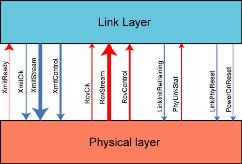
Figure 26-8 on page 695 illustrates the signal interconnect between a port's Physical Layer and its Link Layer. It should be noted that these are the logical signal names provided in the specification and there is no requirement to use these names.
Figure 26-8. Interface Between Link and Physical Layers
Transmit-Side Signals
The transmit-side signals are defined in Table 26-5 on this page. Figure 26-9 on page 697 illustrates the relationship of the XmitControl and XmitStream signals.
Figure 26-9. XmitControl and XmitStream

| Signal(s) | Direction | Definition |
|---|---|---|
| XmitStream | to Physical Layer | XmitStream is a byte-wide bus. It delivers the packet to be transmitted to the Physical Layer one byte at a time. |
| XmitClk | to Physical Layer | Used to clock each character presented on the XmitStream bus to the Physical Layer. The frequency chosen for XmitClk must be sufficient to permit sustained throughput (based on the link speed and width) over the link. |
| XmitControl | to Physical Layer | The state of the XmitControl signal indicates to the Physical Layer that the character currently present on the XmitStream bus is one of the following:
|
| XmitReady | to Link Layer | A Physical Layer implementation may have constraints that prevent it from sending continuous packet traffic. The state of this signal indicates whether the Physical Layer transmit function is ready to start transmitting a new packet. |
| XmitControl State | Definition |
|---|---|
| Data (D) | Outgoing data character. |
| Control (K) | Start Data Packet Delimiter (SDP). |
| Start Link Packet Delimiter (SLP). | |
| End Good Packet Delimiter (EGP). | |
| End Bad Packet Delimiter (EBP; only generated in a switch or router). |
Receive-Side Signals
The receive-side signals are defined in Table 26-7 on this page. Figure 26-10 on page 699 illustrates the relationship of the RcvControl and RcvStream signals.
Figure 26-10. RcvControl and RcvStream

| Signal(s) | Direction | Definition |
|---|---|---|
| RcvStream | to Link Layer | RcvStream is a byte-wide bus. It delivers the received packet character stream to the Link Layer one byte at a time. |
| RcvClk | to Link Layer | Used to clock each character presented on the RcvStream bus to the Link Layer. The frequency chosen for RcvClk must be sufficient to permit sustained throughput (based on the link speed and width) over the link. |
| RcvControl | to Link Layer | The state of the RcvControl signal indicates to the Link Layer that the character currently present on the RcvStream bus is one of the following:
|
| XmitControl State | Definition |
|---|---|
| Data (D) | Incoming data character. |
| Error (E) | Code Violation (i.e, bad encoded character). |
| Control (K) | Start Data Packet Delimiter (SDP). |
| Start Link Packet Delimiter (SLP). | |
| End Good Packet Delimiter (EGP). | |
| End Bad Packet Delimiter (EBP; only generated in switch or router). | |
| Idle (I) | No character being received. |
Other Link Layer to Physical Layer Interface Signals
Other signals in the Link Layer to Physical layer interface are defined in Table 26-9 on this page.
| Signal(s) | Direction | Definition |
|---|---|---|
| LinkInitRetraining | to Physical Layer | Asserted to start retraining due to one of following:
|
| PhyLinkStat | to Link layer |
Indicates Physical Layer is:
When PhyLinkStat = Down, the Link Layer remains in:
|
| LinkPhyReset | to Physical Layer | Asserted due to an unrecoverable error in the Link Layer. |
| PowerOnReset | to Physical Layer | Asserted to the Physical Layer by external logic at power-on time. |