
Switch Performs Packet Forwarding
Switch Port 0
Port 0 May or May Not Have a Physical Layer
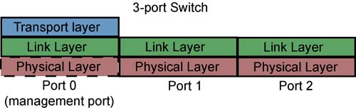
Refer to Figure 25-22 on page 663. A switch must implement Port 0 as an internal port (optionally, it may also be implemented as an external port and could be connected to a link). It is the only switch port that is assigned a LID address (just a base address; it has no PortInfo.LMC for assigning a range of LID addresses to the port). This means it is the only switch port that can be directly addressed. The illustration shows port 0 with an optional Physical Layer and a required Transport Layer. None of the other switch ports implement a Transport Layer (i.e., they have no QPs).
Figure 25-22. Switch Port Zero Is Its Management Port
Switch Port 0's SMI
The switch is required to implement QP0 (its SMI) on port 0 so that the SM can send SMPs to it. Upon receipt of an SMP, the packet is handled by QP0's RQ Logic and is passed to the switch's SMA for processing. If the SMP requires a response, the SMA post a Send request to QP0's SQ. In addition, when the SMA detects certain internal events, it sends an event notification [in the form of a SubnTrap(Notice) MAD] to the SM using QP0.
Switch Port 0's GSI
The switch is required to implement QP1 (its GSI) on port 0 so that the GSMs can send GMPs to it. Upon receipt of a GMP, the packet is handled by QP1's RQ Logic. The RQ Logic uses the packet's Management Class field to determine to which of the GSAs within the switch the packet should be delivered. It is then passed to the appropriate GSA for processing. If the GMP requires a response, the GSA posts a message Send request to QP1's SQ. In addition, when a GSA detects certain internal events, it may send an event notification [in the form of a Trap(Notice) MAD] to the GSM using QP1.
SMPs or GMPs Can Arrive on Any Switch Port
When an SMP or a GMP packet arrives at any switch port other than port 0, the receiving port looks at the packet's DLID to determine if this switch's management port is the destination. If it is, the SMP or GMP packet is internally forwarded to either QP0 or QP1 on switch port 0 for processing. Likewise, once the packet has been processed by the SMA or one of the GSAs, a response MAD may be internally forwarded back to the port that originally received the request MAD and is transmitted back to the originator of the SMP or GMP.
Port Numbering
The management port is always implemented as port 0. Other switch ports are numbered starting at one and are numbered sequentially. The maximum port number would be 255.
Switch's Job Is Packet Switching
Refer to Figure 25-23 on page 664. In a nutshell, on receipt of a packet that is not addressing the switch's management port, the switch performs a lookup in its internal Forwarding Table to determine through which exit port (or ports, if the DLID is a multicast address) the packet must be retransmitted to get to the destination port(s) in the same subnet. The packet is internally forwarded (see Figure 25-26 on page 667) from the receiving port's Link Layer to the selected exit port's Link Layer. The basic process is as follows (refer to Figure 25-24 on page 665 and Figure 25-25 on page 666):
The packet is received and is placed in the receiving port's Link Layer VL buffer selected by the packet's LRH:VL field.
Using the packet's LRH:DLID, a lookup is then performed in the switch's Forwarding Table to select the exit port to which it must be sent.
VL arbitration is then performed and, when it is that VL's turn to transmit a packet, the packet is sent to the exit port's Physical Layer one character at a time for retransmission. The Physical Layer converts each 8-bit character into a 10-bit character, serializes it, and transmits it.
Figure 25-23. Packet Switching
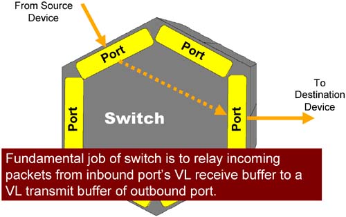
Figure 25-24. Receiving Port's Actions

Figure 25-25. Exit Port's Actions
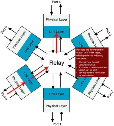
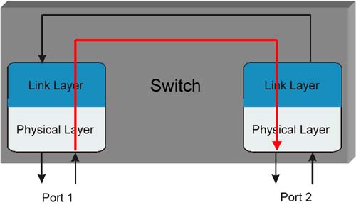
Figure 25-26. Link Layer to Link Layer Transfer
One SLtoVLMappingTable Per Port
Refer to Figure 25-27 on page 668.
The packet arrives on the receiving port (port 2 in the example) and is placed in VL receive buffer 3 by the port's Link Layer (the packet's LRH:VL selects the VL buffer).
The Link Layer uses the LRH:DLID to perform a lookup in the Forwarding Table and determines that the packet is to be internally forwarded to switch port 6's Link Layer.
Upon arrival at port 6's Link Layer, a lookup is performed in port 6's SLtoVLMappingTable attribute using a combination of the receiving port number (2) and the LRH:SL value. The selected entry instructs the Link Layer to accept the packet into the VL1 transmit buffer.
Three Types of Packet Forwarding
A switch implements three different type of packet forwarding:
Directed-Route SMP forwarding. This is the packet forwarding method utilized before LIDs have been assigned and the switch Forwarding Table has been set up by the SM. This subject is covered in detail in “Discovery” on page 871.
Unicast forwarding. This is the method that a switch uses when it receives a packet with a unicast LRH:DLID addressing a destination port.
Multicast forwarding. This is the method that a switch uses when it receives a packet with a multicast LRH:DLID address. In this case, the packet may need to be forwarded to multiple destinations through more than one of the switch's ports.
The sections that follow provide a detailed description of a switch's treatment of unicast and multicast forwarding. A detailed description of directed-route SMP forwarding can be found in the chapter entitled “Discovery” on page 871.
Switch Unicast Packet Forwarding
Two Unicast Forwarding Tables
There are two types of unicast Forwarding Tables that can be implemented in a switch. The designer must implement one or the other, never both. They are:
Linear Forwarding Table (LFT; sometimes referred to as the Linear Forwarding Database, or LinearFDB).
Random Forwarding table (RFT; sometimes referred to as the Random Forwarding Database, or RandomFDB).
In both cases, the exit port is determined by performing a table lookup using the LRH:DLID. The following sections provide a detailed description of each.
Linear Forwarding Table (LFT)
Introduction
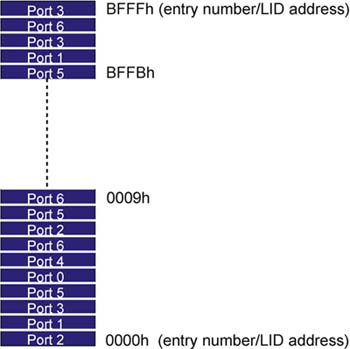
Refer to Figure 25-28 on page 671. The LFT is used to perform lookups for LID addresses in the unicast LID address range (0001h to BFFFh; it should be noted that although entry zero corresponds to LID address 0000h, this address is reserved). For more information, refer to “LID Address Space” on page 133. The table's operation couldn't be simpler—the LRH:DLID is used as an index into the table. The selected entry contains the port number of the exit port to which the packet must be forwarded.
Figure 25-28. Linear Forwarding Table Structure
LFT-Related Attributes
The attributes associated with the LFT are:
- -
LinearForwardingTable.
This is the LFT itself.
- -
SwitchInfo.RandomFDBCap and SwitchInfo.LinearFDBCap.
These two 16-bit, read-only attributes each indicate the size of their respective tables. The one containing a non-zero value indicates that its table exists and its size. The other attribute will be zero, indicating that its respective table has a size of zero and therefore does not exist.
- -
SwitchInfo.LinearFDBTop.
This 16-bit, read-write attribute permits the SM to artificially lower the top of the LFT (i.e., to make it smaller).
LFT Size
The LFT size can be restricted by design, limiting the number of unicast LIDs that are supported by a switch. The maximum possible table size corresponds to the total number of possible unicast addresses (0001h-BFFFh, 48K-1 addresses). The table size is reported in the 16-bit, read-only SwitchInfo.LinearFDBCap attribute element (starting at LID address 0000h and going up). Zero indicates that there is no Linear Forwarding Database (another name for the LFT).
A non-zero value in SwitchInfo.LinearFDBCap indicates the size of the table and the highest unicast LID address supported by the table.
LFT Size Affects SM's LID Assignments
When the SM assigns LID addresses to ports, it must take the size of switch LFTs into account (if the LFT is less than its maximum possible size). In this case, it should only assign ports LID addresses in the range covered by the LFT.
Size Can Be Adjusted
The SM can adjust the actual top of the LFT downward by programming a value smaller than that reported in the SwitchInfo.LinearFDBCap attribute element into the SwitchInfo.LinearFDBTop attribute element.
Packet Discarded under Some Conditions
Switches must discard all unicast packets that meet any of the following conditions:
- The packet's DLID value is greater than the value of SwitchInfo.LinearFDBTop and it is not the permissive LID (PLID) address (FFFFh). For more information on the PLID address, refer to the chapter entitled “Discovery” on page 871.
- The packet's DLID is above the range supported by the LFT and is not the PLID.
- The port number in the LFT entry corresponding to the packet's DLID is set to a port that does not exist.
Forwarding to Switch's SMI or GSI
The SM may program LFT entries corresponding to one or more specific LID addresses with port 0 so that an SMP or GMP packet with one of these DLIDs will be forwarded to switch port 0's SMI or GSI, respectively.
LFT Can Be Inefficient
The LFT structure is such that each successive entry corresponds to the next, sequential DLID. If the DLIDs of packets crossing a switch fall within a relatively small range of values that select entries at the high end of the table, many entries at the low end of the table are unused.
Programming the LFT
From a programming perspective, the LFT is divided into 768 blocks, each consisting of 64, 8-bit entries (a total of 48K – 1 entries). Assuming that the LFT is the maximum possible size, the SM programs the LFT in the following manner:
Repeat step one for the remaining table blocks (1 through 767.)
Random Forwarding Table (RFT)
Introduction
Table 25-5 on page 674 defines the content of each entry in the RFT. This table operates as a content-addressable table rather than as a table wherein an entry is selected using an index value (as does the LFT). When a packet with a unicast DLID is received through a switch port, its LRH:DLID is simultaneously compared to the content of all entries in the table. A match exists if the packet's DLID falls within the range of addresses defined by an entry's Base LID and LMC fields. The packet is then forwarded to the Exit Port defined in that table entry.
RFT Can Be Significantly Smaller Than LFT
The RFT can be significantly smaller than the LFT. While the LFT must have one entry for each individual unicast LID address, a range of up to 128 LID addresses can be defined by each entry in the RFT.
RFT-Related Attributes
The attributes associated with the RFT are:
- -
RandomForwardingTable.
This is the RFT itself.
- -
SwitchInfo.RandomFDBCap and SwitchInfo.LinearFDBCap.
These two 16-bit, read-only attributes each indicate the size of their respective tables. The one containing a non-zero value indicates that its table exists and its size. The other attribute will be zero, indicating that its respective table does not exist.
- -
SwitchInfo.DefaultPort.
A packet that arrives on a port other than the DefaultPort with a unicast DLID that does not match any RFT entry and is not equal to the PLID are forwarded to the port indicated by DefaultPort.
- If the DefaultPort is a port that does not exist, then packets that would otherwise be forwarded to this port are discarded.
- Packets that arrive on the DefaultPort with a unicast DLID field that is not the PLID and does not match an entry in the RFT are discarded.
- -
SwitchInfo.LIDsPerPort.
See the next subsection.
Minimalist Approach
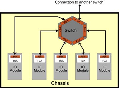
Refer to Figure 25-29 on page 674. In this example, a switch is embedded in a chassis and, with the exception of one switch port, each of the other switch ports is connected to a single port on a TCA. The RFT could be implemented as follows:
- The SwitchInfo.LIDsPerPort would be set to one, indicating that there is only one table entry for each Exit Port definition.
- There is one entry for each port that is connected to a TCA port. Each of these entries would define the range of LID addresses assigned to the TCA port that it is connected to.
- The SwitchInfo.DefaultPort attribute element would be set to the number of the switch port that is connected to the IBA fabric.
Figure 25-29. Switch RFT Has One Entry per Port (port connected to fabric has no entry)
When a packet is transmitted from any of the TCA ports:
- If the DLID matches any entry in the table (other than the entry for port 0), then the packet is destined for one of the other TCA ports in the chassis and it is forwarded to that TCA port through the exit port indicated in the entry that matches the DLID.
- If the DLID matches the entry for port 0 (the switch management port) and it is an SMP or a GMP, then the packet is internally routed to the switch management port's SMI or GSI for processing.
- If the DLID is the PLID address (FFFFh) and it is an SMP, then it is internally routed to the switch management port's SMI for processing.
- If the DLID does not match any of the table entries and it is not the PLID address, then the packet is destined for a port outside of the chassis and it is forwarded through the default port into the IBA fabric.
When a packet arrives from the IBA fabric (through the default port):
- If the DLID matches any entry in the table (other than the entry for port 0), then the packet is destined for one of the TCA ports in the chassis and it is forwarded to that TCA port through the exit port indicated in the entry that matches the DLID.
- If the DLID matches the entry for port 0 (the switch management port) and it is an SMP or a GMP, then the packet is internally routed to the switch management port's SMI or GSI for processing.
- If the DLID is the PLID address (FFFFh) and it is an SMP, then it is internally routed to the switch management port's SMI for processing.
- If the DLID does not match any of the table entries and it is not the PLID address, then the packet is discarded.
A switch that limits the number of entries that point to the same exit port must indicate how many entries can point to the same port in its SwitchInfo.LIDsPerPort attribute element. If the switch does not impose such a limitation, it sets the LIDsPerPort = RandomFDBCap. LIDsPerPort does not apply to port 0 (the switch management port).
Programming the RFT
From a programming perspective, the RFT is divided into 3072 blocks of 16 entries each (each of which has the format shown in Table 25-5 on page 674). Assuming that the RFT were its maximum possible size, the SM programs the RFT in the following manner:
Send a request SMP specifying a SubnSet(RandomForwardingTable) operation with the AttributeModifier = 0 (selecting block 0 in the RFT). The SMP data area contains the 16 entries to be written into the block.
Repeat step one for the remaining table blocks (1 through 767.)
| Item | Length (in bits) | Description |
|---|---|---|
| Base LID | 16 | In combination with the 3-bit LMC field, defines the range of LID addresses as Base LID + (2LMC – 1). |
| Valid Bit | 1 |
|
| LMC | 3 | See the description of the Valid Bit in this table. |
| Reserved | 4 | |
| Exit Port | 8 | Defines the exit port through which the packet will be forwarded. |
Switch Multicast Packet Forwarding
Introduction
Each switch port's Link Layer contains logic responsible for recognizing a packet with a multicast DLID address and treating it accordingly. This entails either a lookup in the optional Multicast Forwarding Table (MFT) or forwarding the packet through a default port. This section provides a detailed description of this logic.
Multicast Only Applies to UD and Raw Packets
Packet multicasting only applies to the UD and raw packet types. RD, RC, and UC packets always utilize unicast DLID and, possibly, DGID addresses.
Multicast Forwarding Table Is Optional
Whether or not a switch implements the MulticastForwardingTable attribute is optional. The SwitchInfo.MulticastFDBCap attribute element indicates the size of the table, or zero if it isn't implemented.
Multicast Packet Handling When Table Is Not Implemented
In this case, when a UD or a raw packet is received with a multicast address in the LRH:DLID field, it is treated as follows:
If the packet arrived on a port other than the one indicated in the SwitchInfo.DefaultMulticastPrimaryPort attribute element (programmed by the SM), then the packet is forwarded through the port number contained in that attribute element.
If the packet arrived on the port indicated in the SwitchInfo.DefaultMulticastPrimaryPort attribute element (programmed by the SM), then the packet is forwarded through the port number contained in the SwitchInfo.DefaultMulticastNotPrimaryPort attribute element (programmed by the SM).
Multicast Forwarding Table Implemented
Table Structure and Lookup Method
Figure 25-30 on page 676 illustrates the structure of the optional switch MulticastForwardingTable attribute. Upon receipt of a UD or raw packet with a multicast DLID address (i.e., an address in the range from C000h through FFFEh), the switch uses the DLID address as a table entry selector, with DLID address C000h corresponding to the first entry in the table, address C0001h corresponding to the second entry, and so on. The selected entry contains a 256-bit mask with the lsb corresponding to switch port 0, the next bit to port 1, and so on. The packet is forwarded through all switch ports (see Figure 25-31 on page 677) with a one in the corresponding bit mask position.
Figure 25-30. Switch MFT Structure
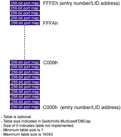
Figure 25-31. Switch Performing a Multicast
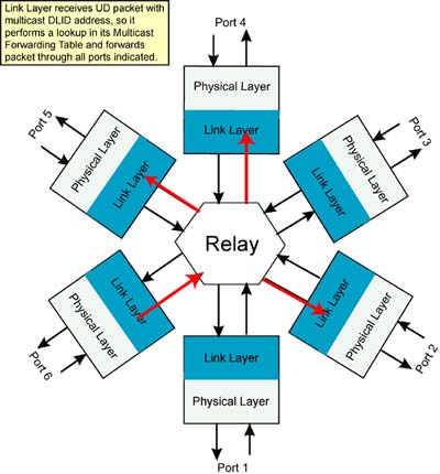
It should be noted that if the bit corresponding to the port that the packet was received on is set to one, the packet is not forwarded through that port.
When the Table Lookup Fails
As noted in Figure 25-30 on page 676, the table size may not include the entire range of possible multicast LID addresses. In this case, when a multicast packet is received with a DLID address above the actual top of the table or if the selected table entry contains all zeros (no ports to forward the packet through), the following action is taken:
- If the packet arrived on a port other than the one indicated in the SwitchInfo.DefaultMulticastPrimaryPort attribute element (programmed by the SM), then the packet is forwarded through the port number contained in that attribute element.
- If the packet arrived on the port indicated in the SwitchInfo.DefaultMulticastPrimaryPort attribute element (programmed by the SM), then the packet is forwarded through the port number contained in the SwitchInfo.DefaultMulticastNotPrimaryPort attribute element (programmed by the SM).
If either the DefaultMulticastPrimaryPort or DefaultMulticastPrimaryPort is set to a port that does not exist, multicast packets that would otherwise be forwarded to the corresponding port are discarded.
Programming the Multicast Forwarding Table
The manner in which the MFT is programmed by the SM is governed by the following facts:
- The data area of an SMP MAD (refer to Table 28-5 on page 788 and Table 28-6 on page 789) is 64 bytes in size. This is the area that contains the attribute data read from or written to an SM attribute.
- The maximum size of the MFT = 16384 entries X 32 bytes (256-bits) per entry = 524,288 bytes. It should be fairly obvious that the entire table cannot be read or written to using one SMP MAD operation.
- From a programming standpoint, the table is divided into 512 blocks of 1024 bytes each, and each block is subdivided into 16 sub-blocks of 64 bytes each (the size of the SMP's attribute data area).
- Each 64-byte sub-block defines two table entries of 32 bytes (512 bits) each.
- The first 32 bytes of the first 64-byte sub-block in the table corresponds to the table entry for LID address C000h, the second sub-block corresponds to the table entry for LID address C001h, and so on.
It is programmed via a series of SubnSet(MulticastForwardingTable) SMP MADs with the following characteristics:
- Management Class = 01h (LID-routed Subn), or 81h (directed-route Subn).
- Method = 02h (Set).
- AttributeID = 001Bh (MulticastForwardingTable).
- AttributeModifier =
- The low-order 10 bits select 1 of 512 blocks in the table. Valid values are 0 to 511 (further limited by the actual size of the table). Any entries in the block beyond the end of the table are read-only and set to 0.
- The four high-order bits select 1 of 16, 64-byte sub-blocks within the selected block.
- The remaining 18 bits must be set to zero.
Additional Information on Multicast Operations
For additional information multicast operations, refer to “Multicasting” on page 563.