
Accessing Device along Partially Configured Path
Three Possible Scenarios
There are three scenarios wherein the entire path between the source and destination ports has not yet been configured with LID addresses and switch Forwarding Tables. They are described in items 2 through 4 in “Four Possible Scenarios” on page 874. The three subsections that follow provide a detailed description of each scenario.
Scenario: Latter-Half of Path Unaddressable
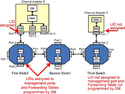
Refer to Figure 31-8 on page 896. This example assumes:
The third switch and CA Y were hot-plugged into the subnet and the SM has to probe the additions.
The SM has programmed the Forwarding Tables in the first two switches and assigned LID addresses to both of their management ports, as well as to CA X port1.
The SM had already used a directed-route SMP to discover the third switch.
It has also discovered that port 2 on that switch is operational, indicating that there is a device at the other end of the link.
The SM now wishes to access an attribute from CA Y port 1.
Figure 31-8. Latter Half of Path Unaddressable
SM Builds Directed-Route SubnGet(NodeInfo) SMP MAD
The SM builds a directed-route SubnGet(Nodeinfo) SMP and instructs CA X port 1's SMI to output it to the port on the other end of the link. The directed-route SMP's contents consists of:
- -
SLID:
CA X Port1's LID address.
- -
DLID:
LID Address of the management port on the second switch.
- Hop Count = 2. The directed-route portion of the path starts at the second switch. From that point, there are two links to traverse to get to the final destination port.
- Hop Pointer = 0.
- D (Direction) bit = 0 (forward).
- InitialPathArray is a three-element array containing:
- The first element is always set to 00h.
- The second element contains 04h, the exit port the packet is to take on the second switch.
- The third element contains 002h, the exit port the packet is to take on the third switch.
- ReturnPathArray is a three-element array containing three bytes, each of which is set to 00h.
- DrSLID is set to the LID address of CA X port 1.
- DrDLID is set to the LID address of the second switch's management port.
Packet Passed to Port 1 SMI for Output to First Switch
Before transmitting the request SMP, the SMI processes the packet. If the DLID is not the PLID, port 1's SMI performs no processing and the packet is output as is. In this scenario, the DLID is not the PLID, so the SMI just outputs the request packet through port 1 with no processing.
First Switch Gets Packet to Second Switch
The request packet arrives at port 4 of the first switch. The DLID is not the PLID address, so the switch performs a lookup in its Forwarding Table and determines that the request packet is to be transmitted through port 3. The packet is transmitted to the second switch.
Second Switch Receives Request Packet
The request packet arrives on port 2 of the second switch. The DLID is not the PLID address, so the switch performs a lookup in its Forwarding Table and determines that the request packet is to be passed to the switch's management port. The packet is internally forwarded to port 0. The BTH:DestQP field indicates that the request packet is to be delivered to QP0, the SMI, for processing. The processing steps taken by the SMI are defined by:
- The state of the D bit (0).
- The relation ship of HopCount and HopPointer. In this case, HopCount is non-zero and HopCount > HopPointer.
The processing steps taken by the SMI are those shown in Figure 31-3 on page 887. They are:
- HopPointer = 0, so the HopPointer is incremented to 1.
- This is a switch, so the request packet's SLID is set to the PLID address.
- The packet's DLID is set to the PLID address.
- The request is output through the switch port contained in InitialPathArray[HopPointer]. This array element indicates that the packet is to be output through switch port 04h.
Request Packet Arrives at Third Switch
The request packet arrives on port 3 of the third switch. It is delivered to the switch management port's SMI because the DLID is set to the PLID address. The processing steps taken by the SMI are defined by:
- The state of the D bit (0).
- The relationship of HopCount and HopPointer. In this case, HopCount ≠ 0 and HopCount > HopPointer.
As a result, the processing steps taken are:
- HopPointer ≠ 0 and this is a switch, so the entry port number is saved in ReturnPathArray[HopPointer]. ReturnPathArray[1] is set to 03h.
- HopPointer is incremented to 2.
- This is a switch, so the request packet's SLID is set to the PLID address.
- The request packet's DLID is set to the PLID address.
- The request packet is output through the port indicated by InitialPathArray[2] (which contains 02h).
Third Switch Outputs Packet on Final Link
The request packet arrives at the destination port on CA Y. Because the DLID contains the PLID address, the packet is delivered to the port's SMI for processing. The processing steps taken are defined by:
- The state of the D bit (0).
- The relation ship of HopCount and HopPointer. In this case, HopCount = HopPointer, so the processing steps taken are those shown in Figure 31-2 on page 886.
The processing steps taken are:
- HopPointer ≠ 0, so the entry port number (01h) is stored in ReturnPathArray[HopPointer]. ReturnPathArray[2] is therefore set to 01h.
- HopPointer is incremented to 3 (one greater than HopCount).
- This is not a switch, and the DrDLID = the PLID address, so the request packet's SLID is set to the PLID address.
- The request packet's DLID address is set to the DrDLID address (which contains the PLID address).
- The request packet's DLID = the PLID address, so the request packet is delivered to the CA's SMA for processing.
- The SMA performs the attribute access, builds a response packet with the D bit set to one, and passes it to port 1's SMI for processing and output.
Response Packet Output by CA Y's Port 1
The processing steps taken by the SMI are defined by:
- The state of the D bit (1).
- The relationship of HopCount (2) and HopPointer (3).
The processing steps taken are those shown in Figure 31-5 on page 889. Those steps are:
- HopPointer is not < HopCount + 1, so HopPointer is decremented to 2.
- This is not a switch, so the response packet's SLID is set to the PLID address (because the CA Y port 1 does not have a LID address assigned yet).
- The response packet's DLID is set to the PLID address.
- The SMI outputs the response packet through the CA port indicated by ReturnPathArray[HopPointer]. ReturnPathArray[2] contains 01h, so the packet is output through CA Y port 1.
Response Packet Arrives at Third Switch
Because the response packet's DLID is set to the PLID address, the response packet is passed to the switch management port's SMI for processing. The processing steps are defined by:
- The state of the D bit (1).
- The value of HopCount (2) and HopPointer (2).
The processing steps taken are those shown in Figure 31-5 on page 889:
- HopPointer < HopCount + 1, and this not a CA.
- HopPointer is decremented to 1.
- This is a switch, so the response packet's SLID is set to the PLID address.
- The response packet's DLID is set the PLID address.
- The response packet is output through the port indicated by ReturnPathArray[HopPointer]. ReturnPathArray[1] = 03h, so the response is output through switch port 3.
Response Packet Arrives at Second Switch
Because the response packet's DLID is set to the PLID address, the response packet is passed to the switch management port's SMI for processing. The processing steps are defined by:
- The state of the D bit (1).
- The value of HopCount (2) and HopPointer (1).
The processing steps taken are those shown in Figure 31-6 on page 890:
- HopPointer is decremented to 0.
- This is a switch and the DrSLID is not the PLID address, so the response packet SLID is set to the LID address assigned to this switch's management port.
- The response packet's DLID is set to the DrSLID address (which contains the LID address of CA X port 1).
- The response packet's DLID ≠ the PLID address and this is a switch, so the switch uses the response packet's DLID to perform a lookup in its Forwarding Table. The Forwarding Table entry directs the switch to output the packet through port 2.
First Switch Receives Response and Forwards to CA X Port 1
The response packet arrives at port 3 on the first switch. The DLID ≠ the PLID address, so the switch uses the response packet's DLID to perform a lookup in its Forwarding Table. The Forwarding Table entry directs the switch to output the packet through port 4.
Response Arrives at CA X Port 1
The response packet arrives at port 1 on CA X. Its DLID matches port 1's assigned address, so the response packet is delivered to port 1's SMI. Because the DLID ≠ the PLID address, no processing is done on the packet and it is passed to the SM.
Scenario: Initial-Half of Path Unaddressable
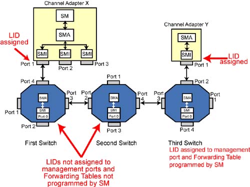
Refer to Figure 31-9 on page 902. This example assumes the following:
The SM had previously discovered and configured the third switch and CA Y. The first and second switches then are added to the subnet by a hot-plug event.
The SM assigned a LID address to CA X port 1.
The SM has not assigned LID addresses to the management ports of the first and second switches.
The SM has not programmed the Forwarding Tables in the first and second switches.
The SM has programmed the Forwarding Table in the third switch, and has assigned LID addresses to the third switch's management port and to CA Y port 1.
The SM has already used directed-route SMPs to discover the first and second switches. It now wishes to perform an attribute access on CA Y port 1.
Figure 31-9. Initial Half of Path Unaddressable
SM Builds Directed-Route SubnGet(NodeInfo) SMP MAD
The SM builds a directed-route SubnGet(Nodeinfo) SMP and instructs CA X port 1's SMI to output it to the port on the other end of the link. The directed-route SMP's contents consists of:
- -
SLID:
CA X Port1's LID address.
- -
DLID:
PLID address.
- Hop Count = 3. The directed-route portion of the path starts at CA X port 1. From that point, there are three links to traverse to get to the third switch.
- Hop Pointer = 0.
- D (Direction) bit = 0 (forward).
- InitialPathArray is a four-element array containing:
- The first element is always set to 00h.
- The second element contains 01h, the exit port the packet is to take on CA X.
- The third element contains 03h, the exit port the packet is to take on the first switch.
- The fourth element contains 04h, the exit port the packet is to take on the second switch.
- ReturnPathArray is a four-element array containing four bytes, each of which is set to 00h.
- DrSLID is set to the LID address of CA X port 1.
- DrDLID is set to the LID address of port 1 on CA Y.
Packet Passed to Port 1 SMI for Output to First Switch
The SMI processing steps are defined by:
- The specified DLID (in this case, the PLID address).
- The state of the D bit (0).
- The relationship of HopCount and HopPointer. In this case, HopCount = 3 and Hop Pointer = 0.
The processing steps are those shown in Figure 31-3 on page 887:
- HopPointer = 0, so HopPointer is incremented to 1.
- This is not a switch, so the request packet's SLID is set to the LID address of CA X port 1.
- The request packet's DLID address is set the PLID address.
- The request packet is output on the CA port indicated by InitialPath Array[HopPointer]. InitialPathArray[1] = 01h, so the request packet is output through CA X port 1.
Request Packet Arrives at First Switch
The request packet arrives on port 4 of the first switch. Because its DLID = the PLID address, the packet is delivered to the management port's SMI for processing. The processing steps taken are defined by:
- The state of the D bit (0).
- The relationship of HopCount and HopPointer. In this case, HopCount = 3 and HopPointer = 1.
The processing steps taken are shown in Figure 31-3 on page 887:
- HopPointer ≠ 0 and this is a switch, so the entry port number is stored in ReturnPathArray[HopPointer]. ReturnPathArray[1] is therefore set to 04h.
- HopPointer is incremented to 2.
- This is a switch, so the request packet's SLID is set to the PLID address.
- The request packet's DLID is set to the PLID address.
- The request packet is output on the port indicated by InitialPath Array[HopPointer]. InitialPathArray[2] = 03h, so the packet is output through port 3.
Request Packet Arrives at Second Switch
The request packet arrives on port 2 of the second switch. Because its DLID = the PLID address, the packet is delivered to the management port's SMI for processing. The processing steps taken are defined by:
- The state of the D bit (0).
- The relationship of HopCount and HopPointer. In this case, HopCount = 3 and HopPointer = 2.
The processing steps taken are shown in Figure 31-3 on page 887:
- HopPointer ≠ 0 and this is a switch, so the entry port number is stored in ReturnPathArray[HopPointer]. ReturnPathArray[2] is set to 02h.
- HopPointer is incremented to 3.
- This is a switch, so the request packet's SLID is set to the PLID address.
- The request packet's DLID is set to the PLID address.
- The request packet is output on the port indicated by InitialPath Array[HopPointer]. InitialPathArray[3] = 04h, so the packet is output through port 4.
Request Packet Arrives at Third Switch
The request packet arrives on port 3 of the third switch. Because its DLID = the PLID address, the packet is delivered to the management port's SMI for processing. The processing steps taken are defined by:
- The state of the D bit (0).
- The relationship of HopCount and HopPointer. In this case, HopCount = 3 and HopPointer = 3.
The processing steps taken are shown in Figure 31-2 on page 886:
- HopPointer ≠ 0, so the entry port number is stored in ReturnPath Array[HopPointer]. ReturnPathArray[3] is therefore set to 03h.
- HopPointer is incremented to 4 (one greater than HopCount).
- This is a switch and the DrDLID ≠ the PLID address, so the request packet's SLID is set to the LID address of the third switch's management port.
- The request packet's DLID is set to the DrDLID (which contains the LID address of port 1 on CA Y).
- The request packet's DLID ≠ the PLID address and this is a switch, so the switch uses the request packet's DLID to perform a lookup in its Forwarding Table. The lookup instructs the switch to forward the request packet through port 2.
Request Packet Arrives at Port 1 on CA Y
When the request packet arrives at CA Y port 1, the DLID matches the port's assigned address. The request packet is therefore passed to port 1's SMI and the SMI passes it to the CA's SMA so it can perform the attribute access.
CA Y's SMA Formulates Response and Passes to SMI
The SMA initializes the response packet as follows:
- D (Direction) bit is set to 1 to indicate this is the response packet making the return journey.
- HopPointer (04h), HopCount (03h), DrSLID = the LID address of CA X port 1, DrDLID = LID of CA Y port 1, InitialPathArray (00h, 01h, 03h, 04h), and ReturnPathArray (00h, 04h, 02h, 03h) are copied as is from the request SMP.
- Since the source port (CA Y port 1) has a LID assigned, the response packet's SLID is set to the port's LID address.
- The response packet's DLID is set to the LID address that was in the request packet's SLID field (the LID address of the third switch's management port.
The SMA passes the response packet to port 1's SMI. Because the response packet's DLID address (it contains the LID address of the third switch's management port) is not the PLID address, the SMI performs no processing and just outputs the packet through CA Y port 1.
Response Packet Arrives at Third Switch
The response packet arrives on port 2 of the third switch, and because the packet's DLID is the LID address of the management port, it is passed to the management port's SMI for processing.
The processing steps taken are defined by:
- The state of the D bit (1).
- The state of HopCount (3) and HopPointer (4).
The processing steps taken are those shown in Figure 31-5 on page 889:
- HopPointer is not < HopCount + 1.
- HopPointer is decremented to 3.
- This is a switch, so the response packet's SLID is set to the PLID address.
- The response packet's DLID is set to the PLID address.
- The response packet is output through the port indicated by ReturnPathArray[HopPointer]. ReturnPathArray[3] = 03h, so the response packet is output through port 3.
Response Packet Arrives at Second Switch
The response packet arrives on port 4 of the second switch, and because the packet's DLID is the PLID address, it is passed to the management port's SMI for processing.
The processing steps taken are defined by:
- The state of the D bit (1).
- The state of HopCount (3) and HopPointer (3).
The processing steps taken are those shown in Figure 31-5 on page 889:
- HopPointer is < HopCount + 1.
- HopPointer is decremented to 2.
- This is a switch, so the response packet's SLID is set to the PLID address.
- The response packet's DLID is set to the PLID address.
- The response packet is output through the port indicated by ReturnPathArray[HopPointer]. ReturnPathArray[2] = 02h, so the response packet is output through port 2.
Response Packet Arrives at First Switch
The response packet arrives on port 3 of the first switch, and because the packet's DLID is the PLID address, it is passed to the management port's SMI for processing.
The processing steps taken are defined by:
- The state of the D bit (1).
- The state of HopCount (3) and HopPointer (2).
The processing steps taken are those shown in Figure 31-5 on page 889:
- HopPointer is < HopCount + 1.
- HopPointer is decremented to 1.
- This is a switch, so the response packet's SLID is set to the PLID address.
- The response packet's DLID is set to the PLID address.
- The response packet is output through the port indicated by ReturnPathArray[HopPointer]. ReturnPathArray[1] = 04h, so the response packet is output through port 4.
Response Packet Arrives at CA X Port 1
The response packet arrives on CA X port 1, and because the packet's DLID is the PLID address, it is passed to the port's SMI for processing.
The processing steps taken are defined by:
- The state of the D bit (1).
- The state of HopCount (3) and HopPointer (1).
The processing steps taken are those shown in Figure 31-6 on page 890:
- HopPointer is decremented to 0.
- Because HopPointer = 0, the response packet is passed to the SM.
Scenario: Middle Portion of Path Unaddressable
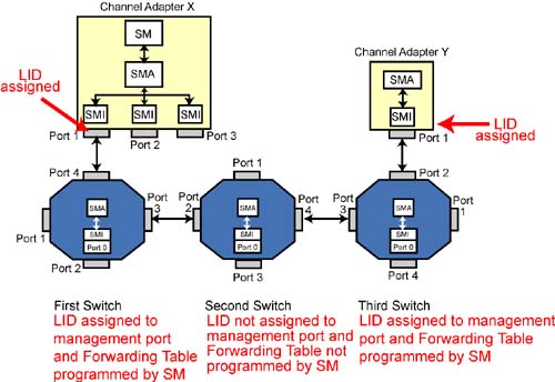
Refer to Figure 31-10 on page 907. This example assumes the following:
The SM had previously discovered and configured the first and third switches and CA Y. The second switch is then added to the subnet by a hot-plug event.
The SM has programmed the Forwarding Tables in the first and third switches.
The SM has assigned LID addresses to the first and third switches' management ports and to CA Y port 1.
In this example, the SM performs an attribute read to read the NodeInfo attribute from CA Y port 1.
Figure 31-10. Middle Portion of Path Unaddressable
SM Builds Directed-Route SubnGet(NodeInfo) SMP MAD
The SM builds a directed-route SubnGet(Nodeinfo) SMP and instructs CA X port 1's SMI to output it to the port on the other end of the link. The directed-route SMP's contents consists of:
- -
SLID:
CA X Port 1's LID address.
- -
DLID:
LID address of the first switch's management port.
- Hop Count = 2. The directed-route portion of the path starts at the first switch's management port. From that point, there are two links to traverse to get to the third switch.
- Hop Pointer = 0.
- D (Direction) bit = 0 (forward).
- InitialPathArray is a three-element array containing:
- The first element is always set to 00h.
- The second element contains 03h, the exit port the packet is to take on the first switch.
- The third element contains 04h, the exit port the packet is to take on the second switch.
- ReturnPathArray is a three-element array containing three bytes, each of which is set to 00h.
- DrSLID is set to the LID address of CA X port 1.
- DrDLID is set to the LID address of port 1 on CA Y.
Packet Passed to Port 1 SMI for Output to First Switch
The SMI processing steps are defined by:
- The specified DLID (in this case, the LID address of the first switch's management port.
- The state of the D bit (0).
- The relationship of HopCount and HopPointer. In this case, HopCount = 2 and Hop Pointer = 0.
Because the request packet's DLID is not the PLID address, port 1's SMI performs no processing on the packet and outputs it as is.
Request Packet Arrives at First Switch
The request packet arrives on port 4 of the first switch. Because the DLID is set to the LID address of the switch management port, the packet is passed to the management port's SMI for processing. The processing steps are defined by:
- The state of the D bit (0).
- The relationship of HopCount (2) and HopPointer (0).
The processing steps taken are therefore those shown in Figure 31-3 on page 887:
- HopPointer = 0, so HopPointer is incremented to 1.
- This is a switch, so the request packet's SLID is set to the PLID address.
- The request packet's DLID is set to the PLID address.
- The packet is output on the port indicated in InitialPathArray[HopPointer]. InitialPathArray[1] = 03h, so the request packet is output on switch port 3.
Request Packet Arrives at Second Switch
The request packet arrives on port 2 of the second switch. Because its DLID is set to the PLID address, it is passed to the switch management port's SMI for processing. The processing steps taken are defined by:
- The state of the D bit (0).
- The relationship of HopCount (2)and HopPointer (1).
Those processing steps are shown in Figure 31-3 on page 887:
- HopPointer ≠ 0 and this is a switch, so the entry port number is stored in ReturnPathArray[HopPointer]. ReturnPathArray[1] is therefore set to 02h.
- HopPointer is incremented to 2.
- This is a switch, so the request packet's SLID is set to the PLID address.
- The packet's DLID is set to the PLID address.
- The request packet is output on the port indicated by InitialPath Array[HopPointer]. InitialPathArray[2] contains 04h, so the packet is output on port 4.
Request Packet Arrives at Third Switch
The request packet arrives on port 3 of the third switch, and, because its DLID is set to the PLID address, it is passed to the SMI of the management port for processing. The processing steps are defined by:
- The state of the D bit (0).
- The relationship of HopCount (2)and HopPointer (2).
Those processing steps are shown in Figure 31-2 on page 886:
- HopPointer ≠ 0, so the entry port number is stored in ReturnPathArray[HopPointer]. ReturnPathArray[2] is therefore set to 03h.
- HopPointer is incremented to 3 (one more than HopCount).
- This is a switch and DrDLID is not set to the PLID address (it's set to the LID address of CA Y port1), so the request packet's SLID is set to the LID address of the third switch's management port.
- The request packet's DLID is set to the address contained in DrDLID (i.e., the LID address of CA Y port1).
- The packet's DLID ≠ the PLID address and this is a switch, so the switch uses the packet's DLID to perform a lookup in its Forwarding Table. The lookup directs the switch to output the request packet through switch port 2, and the packet is output.
Request Packet Arrives at CA Y Port 1
The request packet arrives at CA Y port 1 and its DLID matches the port's assigned address, so the packet is passed to port 1's SMI. The SMI passes the packet to the CA's SMA.
SMA Performs Attribute Access and Builds Response
The SMA initializes the response packet as follows:
- D (Direction) bit is set to 1 to indicate this is the response packet making the return journey.
- HopPointer (03h), HopCount (02h), DrSLID = the LID address of CA X port 1, DrDLID = LID of CA Y port 1, InitialPathArray (00h, 03h, 04h), and ReturnPathArray (00h, 02h, 03h) are copied as is from the request SMP.
- Since the source port (CA Y port 1) has a LID assigned, the response packet's SLID is set to the port's LID address.
- The response packet's DLID is set to the LID address that was in the request packet's SLID field (the LID address of the third switch's management port).
The SMA passes the response packet to port 1's SMI. Because the response packet's DLID address is not the PLID address, the SMI performs no processing and just outputs the packet through port 1.
Response Packet Arrives at Third Switch
The response packet arrives on port two of the third switch and, because its DLID is set to the LID address of the switch's management port, it is passed to that port's SMI for processing.
The processing steps taken are defined by:
- The state of the D bit (1).
- The relationship of HopCount (2) and HopPointer (3).
The steps taken are therefore those shown in Figure 31-5 on page 889:
- HopPointer is not less than HopCount + 1.
- HopPointer is decremented to 2.
- This is a switch, so the response packet's SLID is set to the PLID address.
- The response packet's DLID is set to the PLID address.
- The response packet is output through the switch port indicated by ReturnPathArray[HopPointer]. ReturnPathArray[2] contains 03h, so the packet is output through switch port 3.
Response Packet Arrives at Second Switch
The response packet arrives on port 4 of the second switch and, because its DLID is set to the PLID address, it is passed the SMI of the switch's management port for processing.
The processing steps taken are defined by:
- The state of the D bit (1).
- The relationship of HopCount (2) and HopPointer (2).
The steps taken are therefore those shown in Figure 31-5 on page 889:
- HopPointer is less than HopCount + 1 and this is not a CA, so the response packet is not dropped.
- HopPointer is decremented to 1.
- This is a switch, so the response packet's SLID is set to the PLID address.
- The response packet's DLID is set to the PLID address.
- The response packet is output through the switch port indicated by ReturnPathArray[HopPointer]. ReturnPathArray[1] contains 02h, so the packet is output through switch port 2.
Response Packet arrives at First Switch
The response packet arrives on port 3 of the first switch and, because its DLID is set to the PLID address, it is delivered to the SMI of the switch's management port for processing.
The processing steps are defined by:
- The state of the D bit (1).
- The relationship of HopCount (2) and HopPointer (1).
The steps taken are therefore those shown in Figure 31-6 on page 890:
- HopPointer is decremented to 0.
- This is a switch and DrSLID is not set to the PLID address (it contains the LID address of CA X port 1).
- The response packet's SLID is therefore set to the LID address of the first switch's management port.
- The response packet's DLID is set to the LID address contained in DrSLID (which contains the LID address of CA X port 1).
- Because the response packet's DLID does not contain the PLID address, the DLID is used to perform a Forwarding Table lookup.
- As a result, the response packet is output on switch port 4.
Response Packet arrives at CA X Port 1
The response packet arrives on CA X port 1 and, because its DLID matches the LID address assigned to the port, the packet is passed to the port's SMI. The SMI, in turn, passes the response packet to the SM, completing the attribute access.