
Link Training
Introduction
Link training is the process of obtaining link synchronization between two ports attached via a 1x, 4x, or 12x link.
Link training is initiated when a port's receive logic receives a TS1 Ordered Set (referred to as the beacon sequence) from the port at the other end of the link. This happens when a port's Physical Layer receives a PowerOnReset, a LinkPhyReset (from the Link Layer), or when a hot plug event occurs.
The link training process includes:
Symbol synchronization.
Lane-to-lane de-skew.
Link width and speed negotiation.
The training sequence handshake.
Error recovery from transient link errors.
During the training process, the ports at each end of the link learn each other's capabilities and configure the following parameters:
Link width (1x, 4x, or 12x).
Link speed. The only link speed currently supported is 2.5Gb/s (additional link speeds may be defined in a future revision of the specification).
Optional correction of lane reversal.
Optional correction of inverted received serial data (due to crossed differential signals).
Optional Receiver Training Features
Background: Layout Issues
Two independent optional features are intended to allow on-chip logic to correct non-optimum pin assignments that may occur when connecting an IBA link from one chip to another, or from a chip to a connector. These options can eliminate two common layout issues:
Crossed signals within a differential pair.
Bus bow ties.
Implementing these optional features allows the designer to concentrate on signal integrity and to simplify connections.
Optional Inverted Serial Data Correction Feature
This feature allows the receiver to correct for crossed signals within the receive differential signal pair. To do so, the receiver must test the polarity of the received training sequence data and correct inverted data as part of link configuration. This option does not provide the capability to correct the polarity of transmit data.
The data symbols in the TS1 and TS2 sets (see Figure 26-30 on page 739 and Figure 26-32 on page 743) contain polarity information. When the bit stream on a lane is inverted, the COM and the lane number symbols swap running disparity but still decode to the same value. The TS1 data symbol changes from a D10.2 (4Ah) to a D21.5 (B5h), and the TS2 data symbol changes from a D5.2 (45h) to a D26.5 (BAh) providing a clear indication of lane inversion.
Optional Lane Reversal Correction Feature
This feature allows the designer to connect 4x or 12x ports in reversed lane number order. The receiver logic uses the lane number symbol in the training sequences (TS1 or TS2) to detect and correct the reversed lane connections. If the remote port is incapable of correcting receive lane reversal (because its link width is smaller than that of the local port or the port does not implement this option), the local port reverses its transmit lanes as part of its configuration process.
Link Training State Machine
General
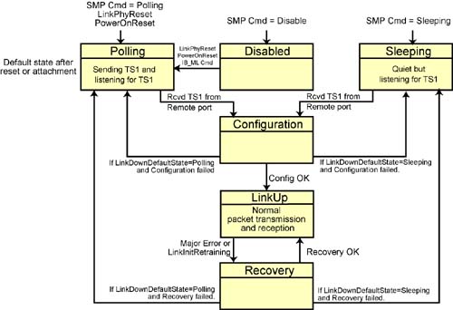
Link training is accomplished by the Link Training State Machine (see Figure 26-11 on page 702). The State Machine is pictured in Figure 26-28 on page 736 and has six possible states:
Sleeping state . In the Sleeping state, the transmitter output is quiescent but the receiver is watching for the receipt of a TS1 Ordered Set from the remote port's transmitter. The port's Physical Layer is in the low-power state. The Sleeping state is referred to as a superstate because it actually consists of two substates.
Polling state.
- The local port's receiver is watching for the receipt of a TS1 Ordered Set from the remote port's transmitter.
- The local port's transmitter is sending the TS1 Ordered Set sequence to the remote port's receive logic.
- -
This is the state after reset is deasserted.
This insures that a newly connected and powered-on port will be recognized by any remote port.
- The Polling state is referred to as a superstate because it consists of two substates.
Configuration state. The link width and speed are configured. Optionally, lane reversal is detected and corrected by the receiver logic. The Configuration state is referred to as a superstate because it consists of four or five substates (there are five substates if the optional lane reversal correction feature is implemented).
Recovery state. When a major error occurs, an attempt to resynchronize is performed in this state and the Physical Layer then returns to normal operation (i.e., the LinkUp state). The Recovery state is referred to as a superstate because it consists of three substates.
LinkUp state. This is the fully operational state wherein packets are transmitted and received.
Figure 26-28. Link Training State Machine
Relationship of PhyLinkStat Signal to the States
The logical PhyLinkStat signal from the Physical Layer to the Link Layer is:
Up, when the Link Training State Machine is in the LinkUp state.
Down, when the Link Training State Machine is in the Polling, Disabled, Sleeping, Configuration, or Recovery state.
SM Can Command a State Change
Using a SubnSet(PortInfo) SMP to update the PortInfo.PortPhysicalState attribute element, the SM can command the Physical Layer's Link Training State Machine to go to one of the following states:
Sleep.
Polling.
Disabled.
PortConfigurationTraining.
LinkUp.
LinkErrorRecovery.
All other state transitions are under the control of the Link Training State Machine.
SM Can Specify Default Link Down State
Using a SubnSet(PortInfo) SMP to update the PortInfo.LinkDownDefault attribute element, the SM can tell the Physical Layer what state to enter when the link goes down. The Sleeping or Polling state may be specified as the default state for link down.
Disabled State
Previous State
The Physical Layer can be transitioned to the Disabled state from any other state by the SM issuing a SubnSet(PortInfo) to change the state of PortInfo.PortPhysicalState attribute element to Disabled.
Next State
The Physical Layer transitions from the Disabled state to the Polling state under any of the following circumstances:
- PowerOnReset.
- LinkPhyReset.
- Receipt of a command over the IB_ML bus (see “Baseboard Management” on page 987).
Description
While the Physical Layer remains in the Disabled state, it has the following operational characteristics:
- PhyLinkStat = Down.
- There is no Physical Layer activity in this state.
- Both the transmitter and receiver are disabled. The transmitter outputs are forced to a quiescent condition and receiver inputs are ignored.
- The SymbolErrorCounter is inhibited.
- The Physical Layer is running on aux power only.
Polling State (Polling and Listening)
Previous State
The Physical Layer enters the Polling state under the following circumstances:
- PowerOnReset. This insures that a newly connected and powered on port will be recognized by any remote port.
- SMP command.
- LinkPhyReset.
- If LinkDownDefaultState = Polling, entered from either of the following:
- Configuration state, if configuration failed.
- Recovery state, if recovery attempt failed.
Next State
The Physical Layer transitions from the Polling state to the Configuration state upon receipt of the TS1 Ordered Set (see Figure 26-30 on page 739) from the remote port's transmitter.
Description
Link configuration is initiated in the Polling state. The Physical Layer is running on bulk power.
See Figure 26-29 on page 738. While in the Polling state, the state machine cycles between the Polling state's two substates: Polling.Active and Polling.Quiet. In both states, the local port's receiver awaits receipt of a TS1 Ordered Set (also referred to as “beacon” sequence) from the remote port's transmitter.
Figure 26-29. Polling Substates
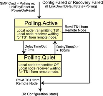
Polling.Active Substate
The local port's transmitter transmits the TS1 Ordered Set repeatedly for a period of 2ms. The Physical Layer then proceeds to the Polling.Quiet state. While in the Polling.Active substate:
- PhyLinkStat = Down.
- SymbolErrorCounter attribute is inhibited.
- TS1 Ordered Sets (and periodic Skip Ordered Sets for clock compensation) are transmitted on all lanes.
- After 2ms without receipt of a TS1 Ordered Set from the remote port's transmitter, the state machine proceeds to the Polling.Quiet substate.
- The state machine proceeds to the Configuration super-state if a TS1 Ordered Set is received from the remote port's transmitter.
Polling.Quiet Substate
The local port's transmitter ceases transmitting TS1s and its receiver awaits receipt of the TS1 Ordered Set from the remote port's transmitter for 100ms. While in the Polling.Quiet substate:
- PhyLinkStat = Down.
- SymbolErrorCounter is inhibited.
- After 100ms without receipt of a TS1 Ordered Set from the remote port's transmitter, returns to the Polling.Active substate.
- The state machine proceeds to the Configuration super-state if a TS1 Ordered Set is received from the remote port's transmitter.
Configuration State
Previous State
The Physical Layer enters the Configuration state from the Polling state upon receipt of the TS1 Ordered Set from the remote port's transmitter.
Next State
The Physical Layer transitions from the Configuration state to one of the following states:
- -
LinkUp state.
The Physical Layer transitions from the Configuration state to the LinkUp state if the configuration attempt completes without error (in other words, training has succeeded).
- -
Polling state.
The Physical Layer transitions from the Configuration state to the Polling state if the configuration attempt fails and the PortInfo.LinkDownDefaultState = Polling.
- -
Sleeping state.
The Physical Layer transitions from the Configuration state to the Sleeping state if the configuration attempt fails and the PortInfo.LinkDownDefaultState = Sleeping.
Basic Description
In the Configuration state, the two ports attempt to teach each other their respective link widths and the link speed each supports. Optionally, the receiver may correct for lane reversal and for inverted lane data. The Physical Layer is operating on bulk power while in the Configuration state. The Configuration substates are described in the following subsections (Refer to Figure 26-31 on page 742).
Figure 26-31. Configuration State

Debounce Substate
The first step is to send a stream of TS1 Ordered Sets for 100ms (and periodic Skip Ordered Sets used by the receiver for lane-to-lane de-skew) indicating that the port has started the configuration process. This allows time for the physical connection to stabilize (debounce delay). The Debounce substate has the following operational characteristics:
- PhyLinkStat = Down.
- SymbolErrorCounter is inhibited.
- The next substate is the RcvrCfg substate.
RcvrCfg Substate
The receiver is enabled to acquire symbol synchronization and to compensate for the lane-to-lane skew (see “Character Boundary Sensing” on page 725 for a detailed description of the symbol synchronization; see “Lane-to-Lane De-Skewing” on page 750 for a detailed description of the de-skewing process), and to perform autoconfiguration (see “Link Training Detail” on page 749).
When the local port transitions to this state, the remote port either may still be sending TS1s (it's still in the RcvrCfg substate) or may have completed receiver training and be transmitting TS2s (it's in the WaitRmt substate; see Figure 26-32 on page 743 for the TS2 format). The receiver can autoconfigure and de-skew while receiving TS1s or TS2s. The transmitter continues to send a stream of TS1s and waits (up to 150ms) for the receiver to complete configuration and de-skew (i.e., training). The RcvrCfg substate has the following additional operational characteristics:
- PhyLinkStat = Down.
- SymbolErrorCounter is enabled.
- The next substate is the WaitRmt substate. If 150ms elapses without successfully completing the configuration of the receiver, the state machine proceeds to the state indicated in PortInfo.LinkDownDefaultState.
WaitRmt Substate
When the receiver has completed training, the transmitter begins to send a stream of TS2s, indicating that the local receiver is trained. The port waits for up to 2ms for the remote port to start sending TS2s indicating that its receiver has completed training. The WaitRmt substate has the following additional operational characteristics:
- A minimum of 16 TS2s are transmitted.
- PhyLinkStat = Down.
- SymbolErrorCounter is enabled.
- The next substate is one of the following:
- The Idle substate.
- The TxRevLanes substate.
- The RcvrCfg substate.
TxRevLanes Substate
If 2ms has elapsed and the remote port has not yet started sending TS2s, a port implementing the optional lane reversal feature reverses its transmit lanes, starts a 2ms delay, and continues to wait for the remote port to start sending TS2s. The final phase begins when the port is both sending and receiving TS2s. The TxRevLanes substate has the following operational characteristics:
- A minimum of 16 TS2s are transmitted.
- PhyLinkStat = Down.
- SymbolErrorCounter is enabled.
- The next substate is either the Idle substate or the RcvrCfg substate.
Idle Substate
In the final step, the port begins transmitting the Idle data stream and waits to receive idle data.When the port is both sending and receiving Idle data, configuration is complete, and the Physical Layer transitions to the LinkUp state. The Idle substate has the following operational characteristics:
- A minimum of 16 symbol times worth of Idle data is transmitted.
- PhyLinkStat = Down.
- Idle data and Skip sets are transmitted on the configured lanes only.
- SymbolErrorCounter is enabled.
- Control passes back to the RcvrCfg substate if 2ms elapses without receiving Idles from the remote transmitter.
- If the remote transmitter starts sending Idles within the 2ms timeout, the Physical layer transitions to the LinkUp state (see“LinkUp State” on page 743).
LinkUp State
Previous State
The LinkUp state is automatically entered from the Configuration state once the local and remote ports have completed link training successfully.
Next State
The Physical Layer automatically transitions to the Recovery state from the LinkUp state when an error is detected by the Link Layer or the Physical Layer.
- The Physical Layer error handling logic monitors major errors and minor errors. When a major error is detected or when a minor error threshold is reached, the Physical Layer exits the LinkUp state and enters the Recovery state.
- When the Link Layer detects a local link integrity error, excessive buffer overruns, or Flow Control update errors, it commands the Physical Layer to initiate link retraining by asserting L_init_train (also referred to as LinkInitRetraining) to the Physical Layer. The Physical Layer exits the LinkUp state and enters the Recovery state.
Description
When in the LinkUp state, the Physical Layer is fully functional. Packets received from the Link Layer are transmitted, and packets received from the remote port are forwarded to the Link Layer. Physical link error handling is enabled. The LinkUp state has the following operational characteristics:
- PhyLinkStat = Up.
- The SymbolErrorCounter is enabled.
Recovery State
Previous State
The Physical Layer automatically enters the Recovery state from the LinkUp state when an error is detected by the Link Layer or the Physical Layer:
- The Physical Layer error handling logic monitors major errors and minor errors. When a major error is detected or when a minor error threshold is reached, the Physical Layer exits the LinkUp state and enters the Recovery state.
- When the Link Layer detects a local link integrity error, excessive buffer overruns, or Flow Control update errors, it commands the Physical Layer to initiate link retraining by asserting L_init_train (also referred to as LinkInitRetraining) to the Physical Layer.
Next State
The Physical Layer exits the Recovery state and transitions to another state under the following circumstances:
- If the link retraining completes successfully, the Physical Layer transitions to the LinkUp state.
- If the link retraining does not complete successfully, the Physical Layer transitions to the state indicated in the PortInfo.LinkDownDefaultState attribute element (i.e., the Polling or Sleeping state).
Basic Description
As described above, the Physical Layer automatically enters the Recovery state from the LinkUp state when an error is detected by the Link Layer or the Physical Layer. The Physical Layer continues to operate on bulk power. The LinkUp state has the following additional operational characteristics:
- Due to an error, the Recovery state may be entered while the Physical Layer is in the middle of packet transmission or reception.
- PhyLinkStat = Down.
- SymbolErrorCounter enabled.
Refer to Figure 26-33 on page 747. The Recovery process is divided into three phases:
1. | The first step of the recovery process is the equivalent of the Configuration.RcvrCfg substate. The local port's transmitter starts by sending a stream of TS1s to trigger error recovery at the remote port. When a TS1 or TS2 is received by the local receiver, it uses the current link configuration (width, lane reversal, lane inversion, and speed) to retrain. |
2. | The second step of the recovery process is the equivalent of the Configuration.WaitRmt substate. It starts when the receiver has completed retraining. The local transmitter starts sending a stream of TS2s and waits for the remote port to starts sending TS2s (indicating that it, too, has completed retraining). When the port is both sending and receiving TS2s, both the local and remote receivers have been retrained, thereby completing the second step of recovery. |
3. | The final step of link recovery is the equivalent of the Configuration.Idle substate. The local port transmits an Idle data stream and waits for Idle data from the remote port. When the port is both sending and receiving Idle data, recovery is complete and the Physical layer returns to the LinkUp state. |
Figure 26-33. Recovery Substates
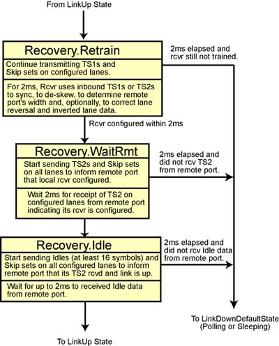
If the recovery process fails at any step, the Physical Layer returns to the state indicated in the PortInfo.LinkDownDefaultState attribute element (i.e., either the Polling or Sleeping state).
The Recovery state consists of three substates (refer to Figure 26-33 on page 747):
- Retrain substate.
- WaitRmt substate.
- Idle substate.
The following subsections provide a description of the three substates.
Step 1: Retrain Substate
The transmitter sends a series of TS1s using the currently configured lanes. The receiver is enabled to reacquire symbol synchronization and then to de-skew the lanes (see “Character Boundary Sensing” on page 725 for additional information on symbol synchronization and “Lane-to-Lane De-Skewing” on page 750 for additional information on the de-skewing process). See “Link Training Detail” on page 749 for additional information on the link training process. The Recovery.Retrain substate has the following operational characteristics:
- A minimum of 16 TS1s are transmitted.
- Symbol synchronization and lane-to-lane de-skew are performed.
- PhyLinkStat = Down.
- TS1 and Skip sets are transmitted only on the configured lanes.
- The port SymbolErrorCounter is enabled.
- When the local receiver has successfully completed retraining, the Physical Layer transitions to the Recovery.WaitRmt substate.
- If the local receiver fails to successfully complete retraining within 2ms, the Physical Layer:
- Increments the LinkDownedCounter.
- Transitions to the state indicated in the PortInfo.LinkDownDefaultState attribute element (i.e., either the Polling or Sleeping state).
Step 2: WaitRmt Substate
The transmitter sends a series of TS2s on the configured lanes. The receiver waits a maximum of 2ms to receive a TS2 on the configured lanes. The Recovery.WaitRmt has the following operational characteristics:
- A minimum of 16 TS2s are transmitted.
- The receiver waits a maximum of 2ms for the receipt of a TS2 from the remote port.
- PhyLinkStat = Down.
- TS2 and Skip sets are transmitted only on the configured lanes.
- The port SymbolErrorCounter is enabled.
- If a TS2 is received within 2ms, the Physical Layer transitions to the Recovery.Idle substate.
- If a TS2 is not received within 2ms:
- The LinkDownedCounter is incremented.
- The Physical Layer transitions to the state indicated in the PortInfo.LinkDownDefaultState attribute element (i.e., either the Polling or Sleeping state).
Step 3: Idle Substate
Both the local the remote ports have retrained and the transmitter now sends Idle data on the configured lanes. The receiver waits to receive Idle data on the configured lanes. The Recovery.Idle state has the following operational characteristics:
- Idle data is transmitted for a minimum of 16 symbol times.
- PhyLinkStat = Down.
- Idle data and Skip sets are transmitted on the configured lanes.
- The port SymbolErrorCounter is enabled.
- The receiver waits for the receipt of Idle data for up to 2ms.
- If Idle data is received within 2ms:
- The LinkErrorRecoveryCounter is incremented.
- The Physical layer transitions to the LinkUp state.
- If Idle data is not received within 2ms:
- The LinkDownedCounter is incremented.
- The Physical Layer transitions to the state indicated in the PortInfo.LinkDownDefaultState attribute element (i.e., either the Polling or Sleeping state).
Sleeping State (Not Polling but Listening)
Previous State
The state machine enters the Sleeping state in one of the following ways:
- SMP command. SubnSet(Portinfo) changing the state of the PortInfo.PortPhysicalState attribute element to the Sleep state.
- In the event of a failure in the link training process while in the Configuration state, the Physical Layer will automatically transition to the Sleeping state if the PortInfo.LinkDownDefaultState attribute element is set to Sleeping.
- In the event of a failure in the link training process while in the Recovery state, the Physical Layer will automatically transition to the Sleeping state if the PortInfo.LinkDownDefaultState attribute element is set to Sleeping.
Next State
While in the Sleeping state, the Physical Layer's transmitter is quiescent, but its receiver is waiting for receipt of a TS1 (the beacon sequence) from the remote port's transmitter. Upon receipt of a TS1, the Physical Layer automatically transitions from the Sleeping state to the Configuration state and switches from aux power to bulk power.
Description
Refer to Figure 26-34 on page 749. While in the Sleeping state, the Physical Layer is operating on aux rather than bulk power. Upon entering this state, the Physical Layer takes the following actions:
- It disables its transmitter and receiver.
- It delays for 400ms to allow all link activity to cease.
- The receiver then awaits receipt of a TS1 from the remote port's transmitter.
- Upon receipt of the TS1, the Physical Layer transitions to the Configuration state and begins link training.
Figure 26-34. Sleeping substates
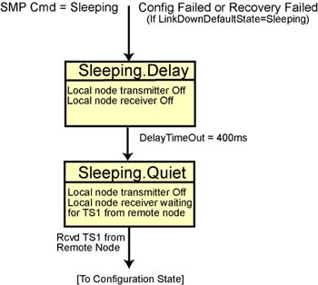
Sleeping.Delay State
The transmitter is quiescent and the receiver is disabled. The Physical Layer remains in this substate for 400ms and then transitions to the Sleeping.Quiet substate. The Sleeping.Delay substate has the following operational characteristics:
- The transmitter is disabled.
- The receiver is disabled.
- PhyLinkStat = Down.
- SymbolErrorCounter is inhibited.
- After 400ms, the Sleeping.Quiet substate is entered.
Sleeping.Quiet State
The transmitter remains disabled, but the receiver is enabled to detect TS1 on all receiver lanes. When TS1 is detected, the Physical Layer transitions to the Configuration state to begin link training. The Sleeping.Quiet substate has the following operational characteristics:
- The transmitter is disabled.
- The receiver awaits receipt of TS1.
- PhyLinkStat = Down.
- SymbolErrorCounter is inhibited.
- When TS1 is sensed, transitions to the Configuration state to begin link training.
Link Training Detail
In both the Configuration.RcvrCfg and the Recovery.Retrain substates, the Physical Layer performs link training. This section describes that process.
The receiver only attempts to configure the link to speeds enabled by the PortInfo.LinkSpeedEnabled attribute element. Although this 4-bit element is read/writable, the only valid setting is 1h (2.5Gb/s).
The receiver may optionally correct inverted receiver data (for more information, refer to “Optional Inverted Serial Data Correction Feature” on page 733). The receiver verifies lane polarity using the 14 data symbols in the received TS1 or TS2 set (see Figure 26-30 on page 739 and Figure 26-32 on page 743). If the lane polarity is not correct (or cannot be corrected), the receiver cannot complete training successfully.
The receiver may optionally correct for reversed lanes (for more information, refer to “Optional Lane Reversal Correction Feature” on page 733). The receiver verifies proper lane order using the lane number symbol (see Figure 26-30 on page 739 and Figure 26-32 on page 743) in the received TS1 or TS2 set. If proper lane ordering is not present (or cannot be corrected), the receiver cannot complete training successfully.
The receiver must only attempt to configure the link to widths enabled by the PortInfo.LinkWidthEnabled attribute element.
- When the 12x width is enabled, the receiver attempts symbol synchronization on all 12 physical lanes (lanes 0 through 11) and verifies that all 12 lanes are receiving TS1s or TS2s.
- When the 4x width is enabled, the receiver attempts symbol synchronization on four physical lanes (lanes 0 through 3) and verifies that all four lanes are receiving TS1s or TS2s.
- When the 1x width is enabled, the receiver attempts symbol synchronization on lane 0 and verifies that it is receiving TS1s or TS2s.
The receiver uses the widest enabled and verified link width for completion of link training and reports that width as the configured link width (in the read-only PortInfo.LinkWidthActive attribute element).
The receiver uses the TS1 or TS2 set as its reference for link de-skew operations.
The receiver must be capable of de-skewing a minimum of six symbol times of total link-to-link skew.
After successful completion of link-to-link de-skew, the receiver must receive eight consecutive error-free TS1 or TS2 sets simultaneously on all configured lanes before it may consider the link successfully trained.
Lane-to-Lane De-Skewing
Not a Problem on a Single-Lane Link
The problem of lane-to-lane skew is obviously only an issue on multi-lane links.
Flight Time Varies from Lane to Lane
Symbols are transmitted simultaneously on all lanes using the same transmit clock, but they cannot be expected to arrive at the receiver at the same time (i.e., without lane to lane skew). A multi-lane link (4X or 12X) may have many sources of lane to lane skew. These sources include but are not limited to:
- Chip drivers and receivers.
- Printed wiring boards.
- Electrical and optical cables
- Delays injected by the serialization and deserialization logic.
- There may be one or two retiming repeaters between the two ports.
The lane-to-lane skew may include components that are less than a bit time (< 400ps), one full bit time (400ps), or full 10-bit symbol time units (10 X X 400ps = 4ns) of skew caused by the retiming repeaters' insert/delete operations (for more information, see “Repeater's Basic Operation” on page 755). A link may have two retiming repeaters, each operating independently on multiple lanes. While performing clock compensation, the repeaters may each insert or delete a Skip symbol independently on each lane. Upon arrival at the port on the other end of the link, the port's receiver must remove this lane-to-lane skew in order to receive and process data on all lanes simultaneously. This process is referred to as link de-skew. Receivers use TS1 or TS2 Ordered Sets to perform link de-skew functions.
If Lane Data Is Unaligned, Byte Unstriping Wouldn't Work
Havoc would ensue if the characters transmitted on each lane simultaneously were to arrive at each lane receiver at different times and were then deserialized and fed to the Byte Unstriping Logic (see “Byte Un-Striping” on page 731). Gibberish would be fed to the Link Layer as packet data.
TS1 and TS2 Are Used to Align Inbound Streams
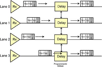
The unique structure and length of the TS1 and TS2 sets, and the fact that they are transmitted simultaneously on all lanes, are used by the receiver's de-skew logic to determine the amount of misalignment between lanes. The specification doesn't define the method used to achieve multi-lane alignment. As an example, the port's receiver logic could compensate for the misalignment by tuning a programmable delay circuit in each lane's receiver (see Figure 26-35 on page 752). The receiver must be capable of de-skewing a minimum of six symbol times (6 symbols X 10 bits per symbol X 400ps = 24ns) of total link skew.
Figure 26-35. Receiver's Link De-Skew Logic
De-Skew Only Done during Link Training/Retraining
TS1 and TS2 sets are only transmitted during initial link training or during link retraining. De-skew is therefore only performed by the receiver at those times and is not done on a periodic basis.
After Alignment, Must Receive Eight Aligned TS1s/TS2s
After compensating for the lane-to-lane skew, the receiver must receive eight consecutive error-free TS1 or TS2 sets simultaneously (i.e., with no lane-to- lane skew) on all configured lanes before considering the slink trained.