Scenario: Sweep at Startup
Refer to Figure 31-1 on page 885 during this discussion.
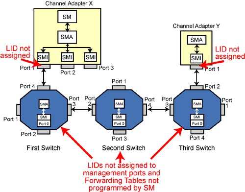
Figure 31-1. At Startup, No LIDs Assigned and Forwarding Tables Not Programmed
No LIDs Assigned Yet
When the SM performs the initial subnet sweep, no LID addresses have been assigned to CA or router ports and to switch management ports. In addition, the Forwarding Tables within switches have not yet been set up.
SM Initially in Discovering State
When the device that contains the SM first starts up, the SM is in the Discovering state (see “Discovering State” on page 858). While in this state, the SM starts probing the subnet (using directed-route SMPs) to determine what devices populate the subnet and how they are interconnected.
Discovery Process
Refer to Figure 31-1 on page 885 during the following discussions. This example assumes the following:
The SM has not yet assigned LID addresses to any CA or router ports, or to any switch management ports.
The SM has not yet programmed the Forwarding Tables in any of switches in the subnet.
Using directed-route SMPs, the SM has discovered all devices in the path to CA Y port 1.
The SM wishes to access one of the attributes associated with CA Y port 1.
SM Queries HCA to Determine When Port 1 Ready
Assume that the SM resides within or behind CA X (but remember that the SM can reside anywhere).
If CA X is an HCA, the SM issues an Open HCA request to the HCA driver. The driver returns a unique handle to be used when requesting future operations targeting this HCA.
After power-up, all ports that have successfully established basic communications with the port at the other end of the link transition to the Initialize state.
The SM issues a Query HCA call to the HCA driver to obtain the operational characteristics of the HCA. The types of information that are returned by the Query HCA call include (but are not limited to):
- The number of physical ports on the HCA.
- A port attribute list for each port. This includes (but is not limited to):
- The range of LIDs currently assigned to a port. Initially, these values are indeterminate.
- Additional GUIDs (if any) that are currently assigned to a port. Initially, these values are indeterminate.
- The LID of the port behind which the SM for this subnet resides. The LID is initially set to the Permissive LID (PLID = FFFFh).
- A bit (IsSM bit) indicating whether an SM resides behind this port. If = 1, then the bit described in the next bullet item has meaning.
- A bit (IsSMDisabled) indicating whether the SM that resides behind this port is currently enabled or disabled.
- The current state of each HCA port.
In this example, the SM uses CA X port 1 as its interface to the subnet (i.e., it's the requester). Port 1's IsSm bit = 1 and it's IsSMDisabled bit = 0.
The SM may begin subnet discovery when port 1 transitions to the Initialize state (indicating that the link is connected to a port on another device and is has completed link training and is operational).
SM Builds Directed-Route SubnGet(NodeInfo) MAD
The SM builds a directed-route SubnGet(Nodeinfo) SMP in system memory and instructs port 1's SMI to output it to the port on the other end of the link. The directed-route SMP's contents consists of:
SLID: CA X port 1's LID or, if a LID has not been assigned yet, the PLID address (FFFFh).
DLID: The device at the other end of first link doesn't have a LID assigned and must therefore be addressed using the PLID (FFFFh).
Hop Count =1 (one link to traverse to get to the device at the end of first link).
Hop Pointer = 0.
D (Direction) bit = 0 (forward).
InitialPathArray is a two-element array containing 00h in the first array element and 01h in the second. The first element is always 00h, and the 01h in the second element indicates the CA port number that the SMI will output the packet through.
ReturnPathArray is a two-element array containing two bytes both set to 00h.
DrSLID (Directed-Route SLID) = PLID (because a LID has not yet been assigned to the source port).
DrDLID = PLID (because a LID has not yet been assigned to the destination port).
The information that will be returned by the NodeInfo request issued to the device at the other end of the link consists of:
- Device type: CA, switch, or router.
- The number of physical ports on the device.
- GUID of CA, switch, or router.
- GUID of receiving port on the target device.
- Device ID and revision.
- The port number that received the SMP.
- Vendor ID.
Packet Passed to Port 1 SMI for Output to First Switch
Before the port 1 SMI outputs the packet, it performs some processing on it. The processing steps taken by the SMI are defined by:
- The state of the D bit (0, in this case).
- The contents of the DLID field (PLID, in this case).
- The relationship of the Hop Pointer and the Hop Count (in this case, Hop Count is non-zero and Hop Count > Hop Pointer).
If the DLID is not the PLID (which it is in this case), no processing would be performed. The SMI would just output the packet as is. In this scenario, however, the processing steps are shown in Figure 31-3 on page 887:
- Hop Pointer is incremented to one.
- Because this is a CA (not a switch), the packet's SLID is set to the LID address of the source port (CA X's port 1). If this port's LID address has not yet been assigned, the SLID is set the PLID address (FFFFh).
- The packet is output through the port number identified in InitialPathArray[HopPointer]. In this case, array element 01h contains the value 01h, so the packet is output through CA X's port 1.
Figure 31-3. SMI Processing Directed-Route SMP Request Packet When Hop Count ≠ 0 and HopCount > HopPointer
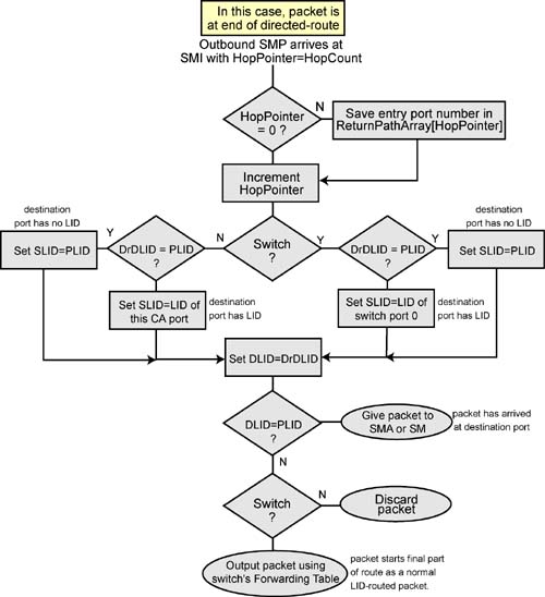
Upon receipt of the SMP packet with DLID = PLID, the switch's receiving port (port 4) sends the packet to switch port 0's SMI for processing. The processing steps are defined by the relationship of the Hop Pointer and the Hop Count (Hop Pointer = Hop Count). The processing steps are shown in Figure 31-2 on page 886:
- Since the HopPointer ≠ 0, the switch's SMI saves the entry port number in ReturnPathArray[HopPointer]. This sets ReturnPathArray[1] = 04h.
- HopPointer is incremented to 02h.
- This device is a switch and the DrDLID = PLID, so the SLID is set to the PLID address.
- DLID is set to DrDLID = the PLID address.
- DLID = PLID, so this is the destination device. The packet is therefore passed to the switch's SMA.
Figure 31-2. SMI Processing Directed-Route SMP Request Packet When HopPointer = HopCount
First Switch Performs Attribute Access and Returns Response
The switch's SMA processes the SubnGet(NodeInfo) request, reads the switch's NodeInfo attribute prepares to return a SubnGetResp(NodeInfo) packet with the requested attribute data. The response packet is initialized as follows:
- D (Direction) bit is set to 1 to indicate this is the response packet making the return journey.
- HopPointer (02h), HopCount (01h), DrSLID (FFFFh), DrDLID (FFFFh), InitialPathArray (00h, 01h), and ReturnPathArray (00h, 04h) are copied as is from the request SMP.
- Since the directed-route is starting from the destination port and the port does not yet have a LID assigned, the packet's SLID is set to the PLID address.
- The packet's DLID is set to the LID address of the port that sourced the request packet (i.e., the request packet's SLID—in this case, FFFFh).
The SMA passes the packet to the SMI of switch port 0.
Prior to sending the response packet, because the D bit is set to one for the return journey, the SMI performs the processing steps shown in Figure 31-5 on page 889:
- HopPointer is decremented to 1.
- The device is a switch, so the packet's SLID is set to the PLID address.
- The packet's DLID is set to the PLID address.
- The SMI outputs the packet through the switch port contained in ReturnPathArray[HopPointer]. HopPointer is currently 1, so the packet is internally forwarded to port 4 (the contents of ReturnPathArray[1]).
Figure 31-5. SMI Processing Directed-Route SMP Response Packet When HopCount ≠ 0 and HopPointer > 1
Response Arrives Back at CA X Port 1
Upon receipt of the packet with DLID = PLID, the CA port passes the packet to its SMI for processing.
Because the D bit is set and HopPointer = 1, the SMI performs the processing steps shown in Figure 31-6 on page 890:
- HopPointer is decremented to 0.
- This is not a switch and the DrSLID = PLID, so the packet's SLID is set to the PLID address.
- The packet's DLID address is set to the DrSLID address (PLID).
- Because the DLID = PLID, the response packet containing the contents of the switch's NodeInfo attribute is passed to the SM.
Figure 31-6. SMI Processing Directed-Route SMP Response Packet When HopPointer = 1
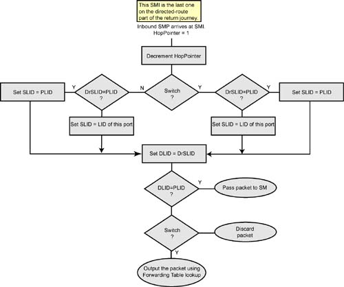
The NodeInfo attribute data identifies the device at the other end of the link as a switch with 4 ports.
Now that the SM knows it's a switch with 4 ports, it will issue additional SubnGet(PortInfo) requests to obtain the state of each switch port (PortInfo.PortState). This discussion assumes that all of the switch's ports are in the Initialize state.
SM Builds Directed-Route SubnGet(NodeInfo) Request MAD
Assume the SM now issues a directed-route SubnGet(NodeInfo) SMP to obtain NodeInfo about the device attached to switch port 3. The directed-route SMP's contents consists of:
SLID and DLID = FFFFh (note, however, that SLID = LID if port 1 on CA X port had already been assigned a LID).
Hop Count = 2 (two links to “hop” to get to the end of the directed portion of the route).
Hop Pointer = 0.
D bit = 0 (forward).
InitialPathArray is a three-element array containing three bytes:
- The first byte is reserved and always 00h.
- The second byte = 01h (the CA output port number).
- The third byte = 03h (the first switch's output port).
ReturnPathArray is a three-element array containing three bytes of zero.
DrSLID = PLID (in this example, the source port has no LID assigned yet).
DrDLID = PLID (because the target port has no LID assigned yet).
Request Packet Passed to Port 1 SMI for Output To First Switch
Before the port 1 SMI outputs the packet, it performs some processing on it. The processing steps taken by the SMI are defined by the relationship of the Hop Pointer and the Hop Count (in this case, Hop Count is non-zero and Hop Count > Hop Pointer). The processing steps are shown in Figure 31-3 on page 887:
- Hop Pointer is incremented to one.
- Because this is a CA (not a switch), the packet's SLID is set to the LID address of the source port (CA X's port 1). If this port's LID address has not yet been assigned, the SLID is set the PLID address (FFFFh).
- The packet is output through the port number identified in InitialPathArray[HopPointer]. In this case, array element 01h contains the value 01h, so the packet is output through CA X's port 1.
The SM sends the packet out on HCA port 1 and it's delivered to port 4 on the first switch. The DLID = PLID, so the packet is sent to switch port 0's (the switch management port) SMI for processing. The processing steps are defined by the relationship of the Hop Pointer and the Hop Count (Hop Pointer > Hop Count). The processing steps are shown in Figure 31-3 on page 887:
- HopPointer ≠ 0 (it's 1 now) and this is a switch, so the entry port number (04h) is stored in ReturnPathArray[HopPointer] (array element 01h = 04h).
- HopPointer is incremented to 2.
- This is a switch, so the packet's SLID is set to the PLID address.
- The packet's DLID is set to the PLID address.
- The switch SMI internally forwards the packet to the switch port indicated in InitialPathArray[HopPointer] (array element 2 contains port 03h).
Request Packet Output to Second Switch
The packet arrives on port 2 of the second switch. Its DLID is set to the PLID address, so the packet is internally forwarded to switch port 0's SMI for processing. The processing steps taken by the SMI are defined by the relationship of the Hop Pointer and the Hop Count (in this case, Hop Count = Hop Pointer). The processing steps are shown in Figure 31-2 on page 886:
- Since the HopPointer ≠ 0, the switch's SMI saves the entry port number in ReturnPathArray[HopPointer]. This sets ReturnPathArray[2] = 02h.
- HopPointer is incremented to 3 (one more than HopCount).
- This device is a switch and the DrDLID = PLID, so the SLID is set to the PLID address.
- DLID is set to DrDLID = the PLID address.
- DLID = PLID, so this is the destination device. The packet is therefore passed to the switch's SMA.
The SMA sets up the SubnGetResp(NodeInfo) response packet using information obtained from the SubnGet(NodeInfo) request packet (however, the D bit is now set to 1, indicating a reverse traversal of the path originally taken by the request packet). The response packet is initialized as follows:
- D (Direction) bit is set to 1 to indicate this is the response packet making the return journey.
- HopPointer (03h), HopCount (02h), DrSLID (FFFFh), DrDLID (FFFFh), InitialPathArray (00h, 01h,03h), and ReturnPathArray (00h, 04h,02h) are copied as is from the request SMP.
- Since the directed-route is starting from the destination port and the port does not yet have a LID assigned, the packet's SLID is set to the PLID address.
- The packet's DLID is set to the LID address of the port that sourced the request packet (i.e., the request packet's SLID—in this case, FFFFh).
- The SMA then forwards the response packet to the switch's SMI for processing and transmit.
Second Switch Sends Response
Prior to sending the response packet, because the D bit is set for the return journey and the relationship of the Hop Count and Hop Pointer, the SMI performs the processing steps shown in Figure 31-5 on page 889:
- HopPointer is decremented to 2.
- The device is a switch, so the packet's SLID is set to the PLID address.
- The packet's DLID is set to the PLID address.
- The SMI outputs the response packet through the switch port contained in ReturnPathArray[HopPointer]. HopPointer is currently 2, so the packet is internally forwarded to port 2 (the contents of ReturnPathArray[2]).
The response packet arrives on port 3 of the first switch. Its DLID is set to the PLID address, so the packet is internally forwarded to switch port 0's SMI for processing. The processing steps taken by the SMI are defined by the state of the D bit (1 now) and the state of HopCount and HopPointer (in this case, HopCount ≠ 0, and HopPointer > 1). The processing steps are shown in Figure 31-5 on page 889:
- HopPointer (currently = 2) < HopCount + 1 (2 + 1 = 3) and this is a switch, so HopPointer is decremented to 1.
- This is a switch, so the response packet's SLID is set the PLID address.
- The response packet's DLID is set to the PLID address.
- The SMI outputs the response packet through the switch port contained in ReturnPathArray[HopPointer]. HopPointer is currently 1, so the packet is internally forwarded to port 4 (the contents of ReturnPath Array[1]).
- The response packet is output on port 4 of the first switch.
The response now arrives on port 1 of CA X. The steps taken are identical to those previously described in “Response Arrives Back at CA X Port 1” on page 881.
The SM proceeds in this manner until it has discovered all ports in subnet. It then uses SubnSet() operations to assign a LID to each port in the subnet.
Figure 31-4. SMI Processing Directed-Route SMP Request Packet When HopPointer > HopCount
Figure 31-7. SMI Processing Directed-Route SMP Response Packet When HopPointer = 0 or in Range HopCount + 2 through 255