
SQ Operation Types
Introduction
The types of send operation WRs that can be posted to a SQ are:
Message read request.
Message write request.
Locked RMW (Read/Modify/Write) request.
It could also be a purely local operation (i.e., the Memory Bind operation).
Specifically, the SQ WR operation types are:
Send. The requester QP's SQ Logic sends a block of data from its local memory to the responder QP's RQ Logic. The WR at the head of the responder QP's RQ tells the responder QP's RQ Logic where to write the data in its local memory. The Send operation is supported on all four IBA transport types and both non-IBA raw transport types.
RDMA Read. The requester QP's SQ Logic issues a memory read request to the responder QP's RQ Logic. The responder QP's RQ Logic reads the requested data from its local memory and transmits it back to the requester QP's SQ Logic. On receiving the requested read data, the SQ Logic writes the data into the local memory buffer(s) specified in the active SQ WQE. The RDMA Read operation is only supported on the RC and RD transport types.
RDMA Write. The requester reads data from its local memory and specifies where the responder is to write the data in its local memory. The RDMA Write operation is supported on the RC, UC, and RD transport service types.
Atomic RMW. The requester QP's SQ Logic issues a RMW request to the responder QP's RQ Logic. The responder QP's RQ Logic performs the requested RMW on the specified local memory location and transmits the data read from the location back to the requester QP's SQ Logic. On receiving the read data, the SQ Logic writes the data into the local memory buffer specified in the active SQ WQE. Atomic operations are only supported on the RC and RD transport service types.
Large Messages Are Segmented into Multiple Packets
A message may be too large to fit into the data payload field of a single packet (i.e., the message size exceeds the PMTU specified in the QP Context—for RC and UC, or EEC—for RD). In this case, the QP divides it up into multiple packets for transmission. A message therefore is transmitted as one of the following:
A single packet (referred to as an “Only” packet).
Two packets: a “First” and a “Last.”
Three or more packets consisting of:
- A “First” packet,
- one or more “Middle” packets,
- followed by a “Last” packet.
Packet Type Specified in Each Packet
Refer to Figure 5-1 on page 80. Every packet of each message contains the Base Transport Header (BTH) field. The BTH:Opcode field specifies what type of message transfer request packet this is. Table 5-1 on page 81 defines the packet Opcode types. The 8-bit Opcode field is divided into two subfields:
Bits 7:5 define the transport service type (RC, UC, RD, or UD).
Bits 4:0 define the message transfer operation type (e.g., Send, RDMA Write, etc.) as well as whether the packet is the “Only”, a “Middle”, or the “Last” packet of a message.
Figure 5-1. The Base Transport Header

The last column in the table defines the types of additional headers immediately following the packet's BTH field, the presence of which are defined by the packet type as indicated by the BTH:Opcode field. Note that ETH stands for Extended Transport Header. The definition of each of the ETHs can be found later in this book (as well as in the “ Glossary” on page 1133).
| Bits 7:5 | Bits 4:0 | Packet Type | Fields That Follow BTH |
|---|---|---|---|
| 000 RC | 00000 | Send First | Data PayLoad |
| 00001 | Send Middle | Data PayLoad | |
| 00010 | Send Last | Data PayLoad | |
| 00011 | Send Last with Immediate | Immediate Data, Data PayLoad | |
| 00100 | Send Only | Data PayLoad | |
| 00101 | Send Only with Immediate | Immediate Data, Data PayLoad | |
| 00110 | RDMA Write First | RDMA ETH (RETH), Data PayLoad | |
| 00111 | RDMA Write Middle | Data PayLoad | |
| 01000 | RDMA Write Last | Data PayLoad | |
| 01001 | RDMA Write Last with Immediate | Immediate Data, Data PayLoad | |
| 01010 | RDMA Write Only | RETH, Data PayLoad | |
| 01011 | RDMA Write Only with Immediate | RETH, Immediate Data, Data PayLoad | |
| 01100 | RDMA Read Request | RETH | |
| 01101 | RDMA Read Response First | Acknowledge ETH (AETH), Data PayLoad | |
| 01110 | RDMA Read Response Middle | Data PayLoad | |
| 01111 | RDMA Read Response Last | AETH, Data PayLoad | |
| 10000 | RDMA Read Response Only | AETH, Data PayLoad | |
| 10001 | Acknowledge packet | AETH | |
| 10010 | ATOMIC Acknowledge packet | AETH, AtomicAckETH | |
| 10011 | CmpSwap packet | AtomicETH | |
| 10100 | FetchAdd packet | AtomicETH | |
| 10101
- 11111 | Reserved | undefined | |
| 001 UC | 00000 | Send First | Data Payload |
| 00001 | Send Middle | Data Payload | |
| 00010 | Send Last | Data Payload | |
| 00011 | Send Last with Immediate | Immediate Data, Data Payload | |
| 00100 | Send Only | Data Payload | |
| 00101 | Send Only with Immediate | Immediate Data, Data Payload | |
| 00110 | RDMA Write First | RETH, Data Payload | |
| 00111 | RDMA Write Middle | Data Payload | |
| 01000 | RDMA Write Last | Data Payload | |
| 01001 | RDMA Write Last with Immediate | Immediate Data, Data Payload | |
| 01010 | RDMA Write Only | RETH, Data Payload | |
| 01011 | RDMA Write Only with Immediate | RETH, Immediate Data, Data Payload | |
| 01100
- 11111 | Reserved | undefined | |
| 010 RD | 00000 | Send First | RD ETH (RDETH), Datagram ETH (DETH), Data Payload |
| 00001 | Send Middle | RDETH, DETH, Data Payload | |
| 00010 | Send Last | RDETH, DETH, Data Payload | |
| 00011 | Send Last with Immediate | RDETH, DETH, Immediate Data, Data Payload | |
| 00100 | Send Only | RDETH, DETH, Data Payload | |
| 00101 | Send Only with Immediate | RDETH, DETH, Immediate Data, Data Payload | |
| 00110 | RDMA Write First | RDETH, DETH, RETH, Data Payload | |
| 00111 | RDMA Write Middle | RDETH, DETH, Data Payload | |
| 01000 | RDMA Write Last | RDETH, DETH, Data Payload | |
| 01001 | RDMA Write Last with Immediate | RDETH, DETH, Immediate Data, Data Payload | |
| 01010 | RDMA Write Only | RDETH, DETH, RETH, Data Payload | |
| 01011 | RDMA Write Only with Immediate | RDETH, DETH, RETH, Immediate Data, Data Payload | |
| 01100 | RDMA Read Request | RDETH, DETH, RETH | |
| 01101 | RDMA Read Response First | RDETH, AETH, Data Payload | |
| 01110 | RDMA Read Response Middle | RDETH, Data Payload | |
| 01111 | RDMA Read Response Last | RDETH, AETH, Data Payload | |
| 10000 | RDMA Read Response Only | RDETH, AETH, Data Payload | |
| 10001 | Acknowledge | RDETH, AETH | |
| 10010 | ATOMIC Acknowledge | RDETH, AETH, AtomicAckETH | |
| 10011 | CmpSwap | RDETH, DETH, AtomicETH | |
| 10100 | FetchAdd | RDETH, DETH, AtomicETH | |
| 10101 | RESYNC | RDETH, DETH | |
| 10110
- 11111 | Reserved | undefined | |
| 011 UD | 00000
- 00011 | Reserved | undefined |
| 00100 | Send Only | DETH, Data Payload | |
| 00101 | Send Only with Immediate | DETH, Immediate Data, Data Payload | |
| 00110
- 11111 | Reserved | undefined | |
| 100
- 101 | 00000
- 11111 | Reserved | undefined |
| 110
- 111 | 00000
- 11111 | Manufacturer Specific Opcodes | undefined |
Description of SQ Operation Types
Send Operation
Description
Figure 5-2 on page 86 provides a step-by-step description of the execution of a Send operation. Execution of a Send operation posted to a QP's SQ causes the QP's SQ Logic to read a message from the local CA's memory, packetize it, and send it to the responder QP's RQ Logic on the remote CA. The sender does not specify where the data is to be written in the remote CA's local memory. Rather, a previously posted WQE on the remote QP's RQ handles the incoming data by writing it to one or more areas of local memory as defined by the Scatter Buffer List specified in the RQ WQE.
Figure 5-2. The Send Operation

It should be noted that none of a Send operation's request packets specify the amount of data in the message. It is therefore possible that the WQE posted on the remote QP's RQ may not specify a large enough memory buffer (or buffers) to hold the entire message. If this proves to be the case, upon receipt of the Send request packet whose data payload cannot be written to local memory due to insufficient buffer space, the RQ Logic will transmit an Invalid Request Nak back to the SQ Logic. For more information, refer to “RQ Logic Behavior after Returning Invalid Request Nak” on page 405.
Supported on All Service Types
The Send operation is supported on all four service types (RD, UC, RD, and UD), and is also supported on raw QPs.
Request Packet Opcodes and Data Payload Size
The BTH:Opcode and the size of the data payload field in a Send request packet is as follows:
- -
Single-packet Send operation.
The entire message is contained in the data payload field and consists of between 0 and PMTU bytes of data. The BTH:Opcode is either “Send Only” or Send Only With Immediate.”
- -
Two-packet Send operation.
The first packet's BTH:Opcode is “Send First” and its data payload field contains PMTU bytes of message data. The second and final request packet has a BTH:Opcode of either “Send Last” or “Send Last With Immediate” and its data payload field contains between 1 and PMTU bytes of message data.
- -
Three or more packet Send operation.
The first packet's BTH:Opcode is “Send First” and its data payload field contains PMTU bytes of message data. The middle request packets each have a BTH:Opcode of “Send Middle” and their data payload fields contain PMTU bytes of message data. The final request packet has a BTH:Opcode of either “Send Last” or “Send Last With Immediate” and its data payload field contains between 1 and PMTU bytes of message data.
Immediate Data Option
If so specified in the posted SQ WR, a 32-bit immediate data item is included in the “Send Only With Immediate” or “Send Last With Immediate” packet of a Send message. In that case, the immediate data item is contained in the ImmDtETH (Immediate Data Extended Transport Header) header in the “Last” or “Only” packet of the message. The presence of this header is indicated by one of the following opcodes (refer to Table 5-1 on page 81) in the BTH:
- “Send Last With Immediate Data”
- “Send Only With Immediate Data”
Unlike the data payload in each of the Send packets, the immediate data isn't written to the destination CA's local memory. When the data payload of the message's last packet has been written to the CA's local memory, the RQ Logic retires the top entry on the RQ and creates a CQE on the RQ's CQ. The immediate data item is stored in the CQE.
RDMA Read Operation
Description
Figure 5-3 on page 90 provides a step-by-step description of the execution of an RDMA Read operation.
Figure 5-3. The RDMA Read Operation
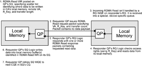
An RDMA Read operation requests that the responder QP's RQ Logic read a message from its local memory and return it to the requester QP's SQ Logic. The following actions are performed:
Earlier in time, a CA builds a message in its local memory. As an example, the CA may be a disk controller that reads a file (or a portion thereof) into its local memory.
By posting a Send operation to its QP's SQ, the CA sends a message to a software application associated with another CA (e.g., a HCA) informing it that the message is ready to be read. The content of its message supplies the HCA with:
- The start virtual memory address (VA) of the area of its local memory that contains the message to be read.
- A remote access key (R_Key) that must be used by the HCA when it subsequently issues an RDMA Read request to fetch the message containing the file data. This key gives the QP issuing the RDMA Read request permission to access the identified area, identifies the area's length, and defines the types of accesses that are permitted in this area (e.g., reads but not writes).
- The amount of data to be read.
Software associated with the CA (the HCA in our example) that received the start virtual memory address, the access key, and the message length then posts an RDMA Read WR to an HCA QP's SQ. The WR specifies:
- The start virtual memory address (VA).
- The access key (R_Key).
- A Scatter Buffer List specifying a list of one or more local memory buffers that the requested read data will be written to when the responder QP's RQ Logic subsequently starts sending back the requested read data.
- The amount of data to be read.
Upon executing the SQ WQE, the requester QP's SQ Logic issues an RDMA Read request packet specifying the start virtual address, the remote access key, and the amount of data to be read.
Using the R_Key supplied in the request packet, the responder QP's RQ Logic validates the access rights.
Assuming that the access rights are correct, the responder QP's RQ Logic reads the requested data from its local memory and sends it back to the requester QP's SQ Logic in a series of one or more RDMA Read response packets.
As it receives each of the RDMA Read response packets, the requester QP's SQ Logic writes the data payload of each packet into its local memory using the Scatter Buffer List in its SQ WQE.
Upon receipt of the final response packet, the requester QP retires its SQ WQE and creates a CQE on the SQ's CQ.
It should be noted that the responder QP's RQ Logic does not use a WQE posted to its RQ to handle an inbound RDMA Read request.
The input parameters supplied by software when it submits the RDMA Read WR to the local QP's SQ are (this is not an all-inclusive list):
- The handle of the QP to whose SQ the request is to be posted.
- The operation type specified is an RDMA Read.
- A Scatter Buffer List and the number of elements in the Scatter Buffer List. Each element defines the start address of a buffer in local memory as well as its length. This tells the QP's SQ Logic where to write the requested read data in its local memory when the data is subsequently returned by the responder QP's RQ Logic.
- The target responder QPN and its Q_Key (only for RD, not RC):
- In RC, the Q_Key is not used and
- the responder QPN was stored in the requester QP's Context when the QP was set up.
- The VA (Virtual start memory Address).
- The R_Key (Remote Access Key).
- The length of the data message to be read (maximum length is 2GB).
Supported on RC and RD
The RDMA Read operation is supported on the RC and RD service types.
Request and Response PSNs, Opcodes and Data Payload Size
The BTH:Opcode in the RDMA Read request packet is “RDMA Read Request.” The VA, R_Key, and the transfer length are contained in the RETH (RDMA Extended Transport Header). The packet contains no data payload.
The opcodes and data payload sizes of the resultant RDMA Read response packets are:
- If the amount of read data requested is less than or equal to the PMTU, then only a single RDMA Read response packet is returned with the following characteristics:
- The BTH:Opcode is “RDMA Read Response Only.”
- The data payload field contains between 0 and PMTU bytes (it is legal to perform a 0-byte RDMA Read; in that case, the resultant response packet does not contain a data payload field).
- The response packet PSN is the same as the request packet PSN.
- If the amount of read data requested will fit in two response packets, those two packets have the following characteristics:
- The first response packet has a BTH:Opcode of “RDMA Read Response First.” Its data payload field contains PMTU bytes. Its PSN is the same as that of the request packet PSN.
- The second and final response packet has a BTH:Opcode of “RDMA Read Response Last.” Its data payload field contains between 1 and PMTU bytes. Its PSN is one greater than that of the request packet PSN.
- If the amount of read data requested requires three or more response packets, those packets have the following characteristics:
- The first response packet has a BTH:Opcode of “RDMA Read Response First.” Its data payload field contains PMTU bytes. Its PSN is the same as that of the request packet PSN.
- The middle packet(s) have a BTH:Opcode of “RDMA Read Response Middle.” Each of their data payload fields contain PMTU bytes. Each of their PSNs is one greater than that of the previously returned RDMA Read response packet.
- The final response packet has a BTH:Opcode of “RDMA Read Response Last.” Its data payload field contains between 1 and PMTU bytes. Its PSN is one greater than that of the previously returned RDMA Read response packet's PSN.
Additional Characteristics
The RDMA Read request packet contains the RETH (RDMA Extended Transport Header) specifying:
- VA.
- R_Key.
- total length of data buffer to read.
After issuing the request, the requester QP's SQ Logic may issue additional RDMA Read requests (or other types of message transfer requests) without waiting for the previously requested read data to be returned. There is one exception—in RD, the SQ Logic may not start the next message transfer until the previous message transfer is fully acknowledged.
If the responder QP's RQ Logic supports multiple outstanding Atomic or RDMA Read operations, it stores each request it receives in a device-specific queue in FIFO order. The FIFO depth is negotiated on a per-QP basis at connection setup time.
- The maximum number of outstanding RDMA Read requests targeting a responder QP at any one time is negotiated at connection establishment time.
- The responder QP may restrict a connection to as few as one outstanding RDMA Read request. In other words, the minimum depth of this queue may be as few as one entry.
RDMA Write Operation
Description
Figure 5-4 on page 93 provides a step-by-step description of the execution of an RDMA Write operation.
Figure 5-4. The RDMA Write Operation

In a Send operation (see “Send Operation” on page 84), the message sender does not specify where the responder QP's RQ Logic is to write the data in its local memory. Rather, the top WQE on the destination QP's RQ contains a Scatter Buffer List defining the local buffer(s) to which the data is to be written.
The RDMA Write operation, on the other hand, instructs the responder QP's RQ Logic to write the data into an area of its local memory that is specified in the RDMA Write request. The following steps are performed:
1. | At an earlier point in time, the CA that the message will be written to prepares an area of its local memory to receive the data to be written. It also prepares an R_Key that must be used to gain access to this area of memory. |
2. | By executing a Send operation, that CA sends a message to another CA (e.g., a HCA) informing it that an area of memory has been prepared to receive a message. It supplies the destination CA with:
|
3. | Software associated with the CA that received the start virtual memory address, the access key, and the buffer length (the HCA in our example) then posts an RDMA Write WR to the local QP's SQ. The WR specifies:
|
4. | The requester QP's SQ Logic issues the first (or only) RDMA Write request packet to the responder QP's RQ Logic. The first packet contains the RDMA
ETH (RETH) specifying the VA, R_Key, and the length of the message to be written (up to 2GB in size). It also contains the first data payload of the data to be written. If the entire message fits in one request packet and the optional, 32-bit immediate data item had been supplied in the WR, the packet's BTH:OPcode is “RDMA Write Only With Immediate” and the ImmDtETH is included. |
5. | The incoming RDMA Write is not handled by a WQE posted on the responder QP's RQ. Rather, the RQ Logic posts it in a special, device-specific queue. |
6. | Using the R_Key supplied in the request packet, the responder QP's RQ Logic validates the access rights and the transfer length. |
7. | Assuming that the access is validated, the responder QP's RQ Logic writes the first (and possibly only) data payload to its local memory. |
8. | If this is a multi-packet message, the requester QP's SQ Logic sends the remaining packets of the message and the responder QP's RQ Logic completes the write to its local memory. |
9. | Upon completion, the responder QP retires the WQE from its RQ and creates a CQE. If the final or only message packet contains the ImmDtETH, the 32-bit immediate data value is stored in the CQE. |
RDMA Write Doesn't Use a WQE on RQ, Except...
With one exception, RDMA operations do not require the use of a responder RQ WQE. The exception is an RDMA Write With Immediate Data. In this case, at the conclusion of the write operation, the responder QP's RQ Logic retires the next WQE on its RQ, creates a CQE in the RQ's CQ, and the immediate data is stored in CQE.
Supported on RC, RD, and UC
The RDMA Write operation is supported on the RC, RD, and UC service types.
Request Packet Opcodes and Data Payload Size
The BTH:Opcode and the size of the data payload field in an RDMA Write request packet is as follows:
- Single-packet RDMA Write operation.
- The entire message is contained in the data payload field and consists of between 0 and PMTU bytes of data.
- The BTH:Opcode is either “RDMA Write Only” or “RDMA Write Only With Immediate.”
- The packet also contains the VA, the R_Key, and the transfer length in the RETH (RDMA Extended Transport Header).
- Two-packet RDMA Write operation.
- The first packet's BTH:Opcode is “RDMA Write First” and its data payload field contains PMTU bytes of message data. The packet also contains the VA, the R_Key, and the transfer length in the RETH (RDMA Extended Transport Header).
- The second and final request packet has a BTH:Opcode of either “RDMA Write Last” or “RDMA Write Last With Immediate” and its data payload field contains between 1 and PMTU bytes of message data.
- Three or more packet RDMA Write operation.
- The first packet's BTH:Opcode is “RDMA Write First” and its data payload field contains PMTU bytes of message data. The packet also contains the VA, the R_Key, and the transfer length in the RETH (RDMA Extended Transport Header).
- The middle request packets each have a BTH:Opcode of “RDMA Write Middle” and their data payload fields contain PMTU bytes of message data.
- The final request packet has a BTH:Opcode of either “RDMA Write Last” or “RDMA Write Last With Immediate” and its data payload field contains between 1 and PMTU bytes of message data.
Immediate Data Option
If so specified in the RDMA Write WR, a 32-bit immediate data item is included in the “Only” or “Last” packet of an RDMA Write message. In that case, the immediate data item is contained in the ImmDtETH (Immediate Data Extended Transport Header) header in the “Last” or “Only” packet of the message. The presence of this header is indicated by one of the following opcodes (refer to Table 5-1 on page 81) in the BTH:
- “RDMA Write Last with Immediate Data”
- “RDMA Write-Only with Immediate Data”
Unlike the data payload in the RDMA Write packets, the immediate data isn't written to the responder QP's local memory. Rather, it is stored in the Receive CQE created upon reception of the RDMA Write's final (or only) packet.
How Can the Immediate Option Be of Use?
The sender of an RDMA Write operation is informed of its completion by the posting of a CQE on the QP's SQ. However, on the receiving end, no CQE is created to signal completion...unless the RDMA Write operation includes an immediate data item in the final packet of the write. As already explained, this causes the CA to whose local memory the data was written to generate a CQE on the CQ associated with the QP's RQ. The CA could be designed so as to generate an interrupt to inform software on its end that the message write to its local memory has been completed. Furthermore, the value of the immediate data item stored in the CQE could be used by software to identify the nature of the message now committed to its local memory.
Atomic RMW Operations
Background: Protecting Access to Shared Resource
In some circumstances a processor must perform a series of two or more accesses to a particular area of memory (for example, a data structure) with the assurance that no other processor has accessed the same memory until the processor's series of accesses have been completed. In other words, the processor needs to perform a series of accesses to that data structure with the assurance that no other processor has accessed the data structure in between this processor's individual accesses to it. The following is an example situation that would require this ability to lock out other entities from accessing a particular target area of memory.
Assume that the host system is running multiple tasks under a multitasking operating system (e.g., OS X, Unix, or Windows). A flag location (or locations) in memory is used to indicate the availability of a shared resource, such as the example data structure in memory. This is referred to as a memory semaphore. When a task needs to access the data structure, it takes the following series of actions:
- The task reads the memory semaphore that protects access to the structure and checks its state (the content of the memory semaphore indicates the availability of the associated data structure).
- If the semaphore location contains zero, this indicates that the structure is available.
- The task would then change the value read to a non-zero value and write it back into the memory semaphore location.
The process of checking and changing the state of the semaphore is frequently referred to as a read/modify/write (RMW) operation. In this manner, the task has reserved the resource (in this case, the data structure) for its own use and may then initiate a series of data structure accesses without fear that another task will be successful in accessing the data structure.
If any other task should check (i.e., read) the state of the respective semaphore while the first task is performing accesses within the data structure, the state of the semaphore indicates that the data structure is currently unavailable. The second task must therefore periodically check the semaphore that controls access to the data structure to determine when the first task has relinquished ownership.
When the first task has completed its accesses within the data structure, it must read from the memory location, set the semaphore value back to zero, and write the resulting value back into the memory location, thereby indicating that the data structure is available again.
Possible Problem: Semaphore Contention
Assume that task A is running on processor A and task B is running on processor B. Task A must access the shared data structure. The programmer executes a load instruction (a memory read) to read the semaphore from memory to test and possibly update it. Processor A initiates and completes a memory read. Task A checks the state of the semaphore and it is zero, indicating that the data structure is currently available. Task A changes the value to a non-zero value in a processor A register (to mark the data structure unavailable to other tasks) and then executes a store instruction (a memory write) to place the updated semaphore back in memory. The store causes processor A to issue a memory write request.
At this time, the task running on processor B also wants access to the data structure, so it also executes a load instruction to read the same semaphore location from memory for testing. As a result, processor B indicates that it wishes to use the fabric (in the case of InfiniBand) to perform its memory read and it may gain access to the semaphore location before processor A. Processor B then initiates a memory read to read the semaphore from memory. Task B determines that the semaphore value is zero, indicating that the data structure is available. It changes the value to a non-zero value and then performs a store to update the semaphore in memory (the same location that processor A will update when it completes its write to the semaphore). When processor B's memory write completes, processor A then performs its memory write to update the same memory location.
Tasks A and B now each believe that the data structure belongs solely to them and mayhem results. This situation could be prevented if processor A were able to perform the memory read, the value test and set in the register, and the memory write as an atomic, indivisible operation with the assurance that no other entity has accessed the same area of memory until the atomic series of accesses (in this case, the memory read followed by the memory write) has been completed.
Two Types of Atomic RMW's
InfiniBand provides two types of atomic RMW operations:
- The Atomic Fetch and Add operation.
- Atomic Compare and Swap If Equal operation.
Atomic Operation Consists of a Request and Ack Packet
Each of the two atomic operation types is implemented using an exchange of:
- An atomic request packet issued by the requester QP's SQ Logic and
- an atomic acknowledge packet returned by the responder QP's RQ Logic.
Neither of the two packets contain a data payload field. Instead, data items required for the operation are carried in ETH fields within the packets.
Request Packet Contains AtomicETH Field
The AtomicETH field contains:
- The quadword-aligned (i.e., the address must be divisible by eight) Virtual Memory Address (VA) of the semaphore.
- The Remote Access Key (R_Key) that grants permission to read and then write the semaphore.
- The Add Data (in the case of a Fetch and Add operation), or the Compare Data and Swap Data (in the case of a Compare and Swap If Equal operation).
Atomic Acknowledge Packet Contents
The atomic acknowledge packet's AtomicAckETH field contains the data read from the semaphore location before it was updated (if, in the case of an Atomic Compare and Swap If Equal, it was updated).
Additional Operational Characteristics
The specification defines the following operational characteristics associated with atomic RMW operations:
- If a CA supports RMW operations, the number of outstanding requests that the CA can handle is negotiated at connection establishment time.
- Upon receipt of an atomic request packet, the responder QP's RQ posts it in a device-specific queue.
- The specification strongly recommends that the atomicity of the RMW be enforced by hardware (rather than software).
- The CA must prevent access to the semaphore location by other QPs on the same CA in the interval between the memory read and write.
- A CA implementation may optionally protect the atomicity of the RMW from memory accesses attempted by other CAs, IO devices, and CPUs. For an HCA, execution of an Query HCA verb call reveals whether or not the HCA supports this enhanced guarantee.
- The VA supplied in the atomic request packet must be quadword-aligned. The responder QP's RQ Logic checks this and returns an Invalid Request Nak if it is not correctly aligned.
Atomic Fetch and Add Operation
Refer to Figure 5-5 on page 98. This operation tells the responder QP's RQ Logic to:
Read a 64-bit value from memory starting at a virtual address divisible by eight in the responder's memory.
Perform an unsigned add using the 64-bit Add Data field supplied in the request packet's AtomicETH field.
Write the result (it must match the memory type at the requester) back to the same virtual address.
Figure 5-5. The Atomic Fetch and Add Operation

The responder's operation must be atomic (i.e., the semaphore location must remain untouched by other entities in the interval between the completion of the memory read and the initiation of the memory write).
The requester specifies the following information in its request packet:
- Remote data address and R_Key.
- Add data.
The responder QP's RQ Logic returns an acknowledge packet containing the original data read from the semaphore.
After the operation, the semaphore location contains the unsigned sum of the original value read from the location and the value from the Add Data field in the AtomicETH header.
When the original read data is returned in the acknowledge packet, it is stored in the requester's memory in the native endian format (big- or little-endian) of the requester. At the responder QP's end, the operation is performed in the endian format of the responder's local memory. If necessary, the data read is converted to big-endian format before it is returned to the requester. All packet fields are in big-endian format on the wire.
Atomic Compare and Swap If Equal Operation
Refer to Figure 5-6 on page 99. This operation tells the responder QP's RQ Logic to:
Read a 64-bit value from memory starting at a virtual address divisible by eight in the responder's memory.
Compare it with the 64-bit Compare Data field from the AtomicETH header.
Based on the results of the comparison, one of the following actions is taken by the responder QP's RQ Logic:
- If they are equal, it writes the 64-bit Swap Data field from the AtomicETH header into the semaphore location.
- If they are not equal, the content of the semaphore location is not changed. In either case, the original value read from the semaphore location is returned to the requester QP's SQ Logic.
Figure 5-6. The Atomic Compare and Swap If Equal Operation

The responder QP's RQ operation must be atomic (i.e., the semaphore location must remain untouched by other entities in the interval between the completion of the memory read and the initiation of the memory write).
The requester QP's SQ Logic specifies the following information in its request packet:
- The start VA of the semaphore (supplied earlier by the CA now acting as the target of the atomic operation request).
- The R_Key (supplied earlier by the CA now acting as the target of the atomic operation request).
- The 64-bit Write data item (referred to as the Swap data).
- The 64-bit Compare data.
The responder QP's RQ Logic returns an acknowledge packet containing the original data read from the semaphore.
All three data values (Compare Data, Swap Data, and the original value read from the semaphore location) are transmitted in the headers of the request and response packets in byte big-endian format. The read (and, if it occurs, the write) of the semaphore in the responder QP's local memory are done in the responder CA's native endian format. The returned semaphore value is stored in the requester's memory in the native endian format of the requester.
Support
The atomic operations are optionally supported on the RC and RD services. HCA support for atomic operations may be discovered by executing the Query HCA verb call. A TCA will indicate its support (or lack thereof) during the connection establishment process (a description of the connection establishment process can be found in “Intro to Connection Establishment” on page 183 and “Communications Management” on page 1069).
Bind Memory Window Operation
Basic Description
Upon execution of this WQE by the QP's SQ Logic, a previously created window (i.e., a memory range) is associated with a previously created region. A window is useful in defining the access rights granted to remote requester QPs attempting access within the local memory window. A region can be overlaid by multiple windows, each defining the access rights granted to one or more remote requester QPs.
Detailed Description
A detailed description of memory regions and windows can be found in the chapter entitled “Memory Protection” on page 297.
Does Not Cause Any Packet Transmission
When it arrives at the head of the SQ and is executed, the Bind Memory Window operation is the only SQ operation type that does not cause any activity on the link. It is an operation purely local within the CA.
Register a Region Prior to Posting Bind Operation to SQ
Prior to posting this WR to a QP's SQ, software must create a region in the CA's local memory (by executing one of the region registration verb calls) for access by this local HCA and to define the HCA's access rights. The region's start VA and length are specified during region registration.
Then Create a Window
Software then creates a Window by executing the Allocate Memory Window verb.
Post the Request
After Region and Window creation, software may post a Bind Memory Window WR to a QP's SQ. The WR specifies:
- The handle of the Region to which the Window is to be bound.
- The handle of the Window to be bound to the specified Region.
- The remote access key (R_Key) currently associated with the window.
- The start VA and length of the window.
- Access rights granted to remote requester QPs when attempting accesses within this window.
Execution of the Post Send Request verb call to post this request type returns an R_Key associated with the Window. The specified Window is not actually bound to the region, however, until the SQ WQE is executed by the QP's SQ Logic.
Remote Access Within Window
When performing an access within a Window, a remote requester QP's SQ Logic supplies the VA, the buffer length, and the R_Key in its request packet.
Support
The bind operation is supported on the RC, RD, and UC service types.
SQ Operation Support by Type
Table 5-2 on this page defines under what circumstances a CA must support each of the SQ operation types. Note that the Resync operation only pertains to the RD service type and has not yet been covered. A detailed description of Resync can be found in “Resync Operation” on page 499.
| Operation Type | Service Type | |||||
|---|---|---|---|---|---|---|
| Supported on RC? | Supported on UC? | Supported on RD? | Supported on UD? | Supported on Raw Datagram? | ||
| Send | Yes | Yes | Yes | Yes | Yes | |
| Resync | No | No | Yes | No | No | |
| RDMA Write | Yes | Yes | Yes | No | NA | |
| RDMA Read | Yes | No | Yes | No | NA | |
| Atomic operation | Optional | No | Optional | No | NA | |