Software development is about building models. You begin with the use-case model to capture stakeholder concerns; you refine the use-case model into an analysis model, which also formulates a high-level overview of the system; you strategize how the system will run on the execution platform with the design model, and in the implementation model, you have the actual codes and binaries. However, you do not build a system model by model. Instead, you do so use case by use case. You take each use case and refine and realize it progressively through the various models. When you complete the work on a use case, you deliver all artifacts associated with the use case in a single package—we call this a use-case module. A use-case module comprises use-case slices of each model. Use-case modules are developed separately and are composed to yield the complete system.
As we saw in Part I of the book, the concept of separation helps us deal with complexity. Models are an alternate way to deal with complexity—through abstraction. Instead of separating the problem into smaller parts, you often need to look at the problem in its entirety. For example, when you want to establish an overall structure for your system, you definitely need to consider the entire system. When you want to design user interfaces, you need to consider multiple uses cases for an actor at once. Here, you cannot afford to go into every detail. You work with a high-level abstract description. You achieve this with the help of models.
So, what are models? A model is a description of the system from a particular perspective and from a chosen level of abstraction or detail. In a given model, you want to consider only things that are relevant to that perspective and that level of detail. Thus, you deliberately suppress and ignore details that are not relevant. For example, you might have a user interface model. In this case, you are only interested in how information is displayed, how you navigate from screen to screen, and so on. How information is stored or retrieved is irrelevant to a user interface model, and so is validation checks used on each piece of information.
When working with a model, you must first define a language for it. This language identifies the constructs or element types that you have at your disposal to adequately represent the system from the model’s chosen perspective. For example, you might want to describe the user’s interaction with the user interface, so you may have such elements as screens, pop-ups, buttons, and so on. The language also defines the different kinds of relationships between these elements. For example, a screen can contain some buttons and labels—so containment will be one kind of relationship. You can also navigate from one screen to some other screen, but not to others—thus, navigation is a kind of relationship that exists in the user interface model. With UML, you can easily define stereotypes to denote the different kinds of elements you are using in each model as well as the relationships between elements across models.
The constructs in a model are organized within containment hierarchies with some namespace. For example, there can be layers containing packages, which contain other packages and classes. A model can have more than one structure. As mentioned in earlier chapters, models other than the use-case model will contain at least two structures—an element structure and a use-case structure.
During development of a system, one of the first things you do is identify a set of models to describe your system adequately. If you have too few models, you might not have a good understanding of the system in its entirety. This happens when you rush into coding too quickly—you get pulled into the details and gradually lose the big picture. There are just too many details within the code, and you need to operate at a higher level of abstraction. So, more often than not, you have more than one model and, as you would expect, a more complex system needs more models. Some models are driven by business processes and application needs; others are driven by technology. But with more models, you must invest some effort to keep the integrity between models. This will certainly be a chore if you were to do it manually. Thanks to more powerful modeling tools, models can be kept synchronized with a click of a button.
The deliverables of a project have a direct relationship with the models you have chosen. The more models you identify, the more work you must do. You should never attempt to over-model. You use a new model only if you are unable to express what you want with the models you already have. If, on the other hand, you have a complex system and choose to have fewer models than necessary, you will end up with loose bits of undigested information. So, from a pragmatic standpoint, you begin with some minimum set of models at the beginning of the project and when they are insufficient, you identify more. Once the models are identified, the whole project life cycle will be about building these models.
In the context of use-case-driven development, there are several basic models: the use-case model, the analysis model, the design model, and the implementation model. Before we proceed further, we want to emphasize that these models are the only models, but they represent a minimum set. In addition, you need a tool that supports multimodels to maintain the integrity between the models. We explain the purpose for each of these models.
The use-case model serves as an agreement between the stakeholders (or customers) of the system and the developers on what the system should do and what qualities the system should have. Since the use-case model is meant for the stakeholders, their specifications are often expressed in the language understandable to the stakeholders. So, you try to describe it in a nontechnical way, and this is normally achieved using plain English.
The use-case model captures the users’ and stakeholders’ concerns by describing how actors will use the system and the acceptable behaviors that the desired system should produce. It comprises actors and use cases. For a larger system, you may choose to organize use cases within packages. In addition, different use cases may be related through relationships such as include, generalization, and extend. These relationships facilitate the reuse of system behaviors and the addition of new behaviors on top of existing ones, as we discussed in the Part II of the book. Since use cases represent a good way of understanding the system, it is beneficial to preserve the structure of the use-case model in the rest of the models.
Use-case specifications describe the system’s desired behavior from the external perspective using the end-user representatives’ language, which is often in some natural language, such as English. To end-user representatives, this textual description of the system is a lot easier to understand than a more formal representation in UML. But there is a price to pay, because while natural language is intuitive, it is imprecise and there are some details in use-case specifications that one just cannot specify with English. For example, details such as the relationships between information to be captured, how information is to be presented, and conflicts between use cases simply cannot be expressed clearly with textual description. We need a more precise representation. This is possible with the analysis model.
Analysis is a refinement of the requirements with the goal of creating precise specification of requirements. Its purpose also is to find abstractions in the form of classes that make the requirements clearer as compared to plain use-case specifications. In fact, it is possible to formally define the sequence of actions the system performs to realize the use case in precise notation. This is what recent developments such as Executable UML attempt to achieve. Executable UML attempts to extend UML with precise action semantics to make the analysis model executable, as if it were the code itself, although in a platform-independent form. Such formal specifications are too overwhelming for the use-case model.
As mentioned earlier, each model has its own language and its own constructs to help you describe the system from that modeling perspective. To achieve this, the analysis model contains two structures:
Analysis element structure. This comprises analysis classes organized in packages and layers. As mentioned earlier, these analysis classes are empty.
Use-case analysis structure. This comprises use-case slices that add the content into the analysis element structure.
The language of an analysis model is a subset of the UML, which is deliberately chosen to be platform-independent so that you need not go into the details. To abstract away low-level details, the analysis model provides three stereotyped analysis classes (or constructs): boundary, control, and entity stereotyped classes.
A boundary class is used to model the interaction between the system and its actors (i.e., users and external systems). The interaction often involves receiving and presenting information and requests from and to users and external systems. Boundary classes act as mediators between the system’s surroundings (i.e., actors) and the system. It shields the system from changes in its environment. If such changes occur, only boundary classes are affected.
A control class is responsible for the coordination, sequencing, transaction, and control of other objects and is often used to encapsulate control related to a specific use case. An instance of a control class often shares the same lifetime as a use-case instance. Frequently, it is instantiated when the use case is instantiated and is terminated when the use-case instance terminates. Control classes can also represent complex calculations and business logic.
An entity class is used to model information in the problem domain. Such information is long-lived and often persistent. An entity class manages and stores such information. It encapsulates changes in the data structure or datastore. An entity class is use-case-generic and often participates in multiple use-case realizations.
These stereotypes are associated with corresponding icons, depicted in Figure 10-1. These icons help us recognize them quickly when they appear in UML diagrams. Stereotypes are extremely powerful tools that help you to quickly understand the responsibilities of a particular class even without looking at its operations or responsibilities.
These analysis stereotypes are now de facto standards in the software development community when conducting analysis. Those of you who are familiar with the OOSE approach in which they were first introduced, or with the Unified Process, should be familiar with these stereotypes.
In creating an analysis model, which is a refinement of the use cases, you also identified the elements (in the form of analysis classes) that realize the use cases as well as their responsibilities. This often reveals reusable elements across use cases. You organize these abstractions into a high-level element structure of the system. The constructs you use in the analysis model are deliberately high level and platform-independent so that you are not pulled into implementation details too early.
At this level of abstraction, you have fewer elements to manipulate, and you can rapidly identify the responsibilities of each of these elements. You can quickly evaluate the system’s element structure against some key use cases and scenarios. In addition, analysis constructs (such as analysis classes) help you localize possible changes to the system. These analysis classes are refined as you proceed to design and implementation.
Orthogonal to the element structure is the use-case structure. The use-case structure contains both non-use-case-specific slices and use-case slices. Use-case slices are for the purpose of preserving the separation of use cases from analysis to design and to implementation. Each analysis use-case slice contains the specifics of a use case in the analysis model.
Thus, you see that the purpose of the analysis model is twofold. First, it is a refinement of the use-case model. Second, it is also where you begin to describe the internal structure of the system. This serves as an excellent input to the design model. The boundary, control and entity classes in analysis are candidates to become components during design. Sometimes, one of such classes will evolve into a component by itself during design. Other times, several closely related analysis classes will evolve into a component.
The design model is a refinement of the analysis model and deals with the specifics of the execution platform. Thus, the design model must plan many important details. It has to address the multitude of implementation languages and technologies. It has to organize the distribution of the system across multiple processing nodes and arrange multiple implementation languages. Even if you decide to use a single platform like J2EE, you still have many languages to work with—Java, JSP, SQL, and more. In addition, there are also different implementation technologies for you to choose from—technologies that deal with persistency, presentation, and so on. Since a design model must prepare many things, it is significantly more complex than the analysis model. Therefore, it is advisable to keep the analysis model and the design model as distinct models. You use the analysis model to define the high-level structure and the design model to refine this structure and incorporate the details.
To describe platform specifics, the design model must contain more constructs and, hence, more structures than the analysis model. It contains the following structures:
Deployment structure. The deployment structure comprises processing nodes used in the system, the nodes the system needs to interface to, and the links between these nodes.
Process structure. The process structure comprises active elements such as processes and threads. These processes and threads execute within nodes in the deployment structure.
Design element structure. The design element structure comprises design classes organized into layers, subsystems, and packages. Some elements are refinements of boundary, control, and entity in the analysis element structure. Classes are refined with attributes and operations. Interfaces appear here. Classes are executed in the context of active elements in the process structure.
Use-case design structure. The use-case structure runs orthogonally across the design element structure. It comprises use-case slices, aspects, class extensions, and so on.
Since, the design model is a refinement of the analysis model, you expect the structure of the analysis model to be preserved in the design model. This means that you find packages in the design element structure corresponding to packages in the analysis element structure. You also find classes in the design model that are derived from the classes in the analysis model. Likewise, the use-case slices you identify during analysis will be refined during design.
Figure 10-2 illustrates what it means to have the design model preserve the structure of the analysis model. In essence, the structures within the analysis model are all platform-independent. The design model comprises structures that are cleanly divided into two parts: one part is minimal design, and the other part is platform-specific.
The minimal design part corresponds to what you find in the platform-independent analysis model. We consider it minimal design in the sense that even though it has a defined implementation language (e.g., Java), it makes no use of platform- or technology-specific calls (e.g., classes specific to J2EE). Thus, the minimal design part in the design model is quite simple, and the elements therein are traced directly from the analysis model (which is platform-independent). This clear separation is crucial in making the design model significantly more understandable without the entanglement of platform specifics. It also improves portability.
In the minimal design part, there are boundary control and entity classes. But to distinguish them from their analysis counterparts, we give them different stereotype icons. These are shown in Figure 10-3.
In addition, there are classes to represent data/messages that get passed between boundary, control, and entity classes, and there are classes for handling exceptions, and so on. Since the design model deals with platform specifics, there are also many other kinds of design elements and probably more stereotypes.
We earlier mentioned that individual boundary, control, and entity classes, or groups of them, will evolve into components in design. These components will have interfaces that are derived from the responsibilities of analysis classes. We call these interfaces minimal design interfaces. During design, we also incorporate platform specifics, and consequently, components also have platform-specific interfaces. For example, a component may have a Web-based HTTP interface, or perhaps interfaces for distribution, such as J2EE remote interfaces. We discuss more of these platform-specific interfaces in Chapter 15, “Separating Platform Specifics with Platform-Specific Use-Case Slices.”
You usually work on the design model and the implementation model together, so even though they are distinct models, you make changes on them in a single activity. You conduct tests together with design and implementation. Design is not complete until you know exactly how to test the design elements, and implementation is not complete until you pass these tests.
You take each use-case slice in analysis and refine it into design. You also start to incorporate user interface elements and elements to support distribution, persistence, and so on. You keep these elements separate from the boundary, control, and entity classes in both the element structure and the use-case structure. In the element structure, you have subpackages for these elements. Similarly, in the use-case structure, you have sub-use-case slices.
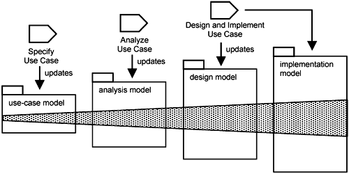
When you build a system, you do not build it model by model. Instead, you build it use case by use case. You first identify the use cases for the system. Thereafter, you take each use case, one at a time, to specify it, analyze it, design it, and implement it. As you build each use case through the various models, you update the corresponding use-case slice in the respective models. These slices are shaded in Figure 10-4.
As you work on a use-case slice (e.g., the use-case slice in design), you start with the use-case slice upstream (e.g., the use-case slice in analysis), do some refinement, and add a little more. So, as depicted in Figure 10-4, each use-case slice downstream is bigger and more complex than the one upstream. This is the same with models. Downstream models are more complex than upstream models because downstream models must take into consideration more and more issues. This is why in Figure 10-4, each downstream model is depicted larger than the preceding one.
Thus, the way you develop the system is by gradually refining use-case slices through the various models. The structure of the use-case model is essentially preserved throughout all models downstream through the use-case slices of those models. This is useful for several reasons. First, this helps us understand the models downstream. You can easily identify what each use-case slice is doing by looking at the corresponding use case.
Second, software development is not a linear progression from use case to implementation. You frequently need to move back and forth in and update the various models. Preserving the structure of the use-case model helps you move from one model to another seamlessly and in a controlled manner. You do a little bit of the use-case specifications, move to its analysis, explore the interactions, and go back to the use-case specifications to clarify some missing details with the stakeholders. Maybe as you are working on the design, you need to revisit the system structure and go back to the analysis slice. Or maybe you need to clarify some special requirement for the use-case specification. This moving back and forth occurs frequently during the early iterations of the project when you are exploring design options, evaluating risks, and establishing an architecture baseline for the system.
Let us see what happens if you do not preserve the structure of the use-case model downstream. In this case, each downstream model is structured in its own way; it defeats the purpose of spending time structuring the use-case model. It means that you must understand completely different structures and maintain a mapping between these structures. If there are no formal rules for this mapping, it will be difficult to assure consistency between models. Not only that, but it actually removes seamlessness as you progress from one model to the next.
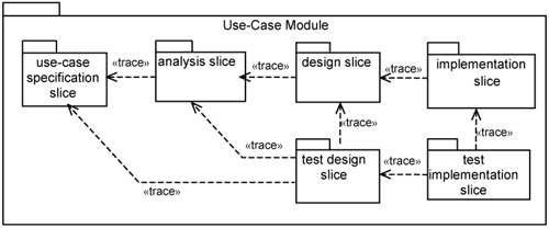
Since you work on slices of various models for each use case together, it makes sense to collate all these slices into a single package. We call such a package a use-case module. A use-case module contains a use-case specification slice (of the use-case model), an analysis slice (of the analysis model), a design slice (of the design model), and an implementation slice (of the implementation model), as depicted in Figure 10-5.
In addition, there are slices of the design model and the implementation model for the purpose of conducting tests. Each test slice contains classes and class extensions needed to drive a particular slice through a test scenario. It also has extensions to perform instrumentation to collect test results. The number of test slices you need depends on the types of tests you will perform on the use-case module. For example, you might have a test slice for functional tests and a test slice for performance tests.
The «trace» dependencies in Figure 10-5 indicate that there exist some rules for you to derive elements from one upstream model to an element in the downstream model. Frequently, such rules are described informally by the architect as development guidelines and principles to be adhered to by the development team. However, there are certainly opportunities for you to formalize the derivation rules for possible automation. In fact, there are tools available today that provide some degree of automation to generate the downstream model at least partially. Since the upstream model is more abstract than the downstream one, you definitely need to define additional parameters for this automatic generation to be possible.
When developing a system comprising use-case modules, you may be able to treat each use-case module as a project that is developed independently, so you might have in your hard disk or some central development repository a root folder for a use-case module and subfolders for each slice in the use-case module.
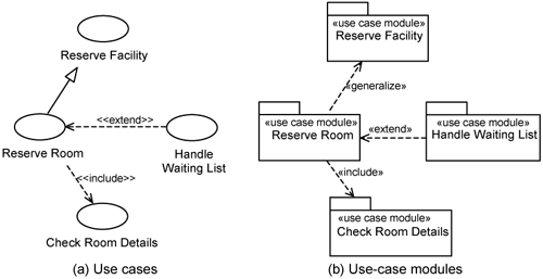
Just as there are relationships between use cases, use-case modules have relationships with each other. The relationships between use-case modules are the same as between use cases: generalization, include, and extend, as exemplified in Figure 10-6.
Use-case module relationships can be used in two complementary ways. First, from a forward engineering perspective, we can use relationships between use cases to drive the relationship between use-case modules. In other words, use-case modules preserve the relationships between use cases. This is illustrated by Figure 10-6, which shows a correspondence between use-case relationships and use-case-module relationships. For example, the Reserve Facility use case is a generalization of the Reserve Room use case, and so the Reserve Facility use-case module is a generalization of the Reserve Room use-case module.
Second, the relationship between use-case modules can be used as a means to detect access violations in which an element in one use-case module has an illegal relationship with another element in another use-case module. The relationship between two use-case modules is an aggregate of all the relationships between elements of one use-case module to elements of the other. Thus, by aggregating these lower level element relationships, we check if they conform to the relationships at the use-case-module level.
Let us consider the relationship between the Reserve Room and Handle Waiting List use-case modules. In this case, we allow an element in the Handle Waiting List use-case module to extend an element in the Reserve Room use-case module, but not vice versa. We can be stricter by saying that no element in the Handle Waiting List use-case module can be a specialization of an element in the Reserve Room.
By watching the relationships across use-case modules, we can detect any access violations early whenever they occur and make the necessary changes quickly.
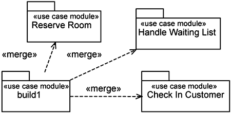
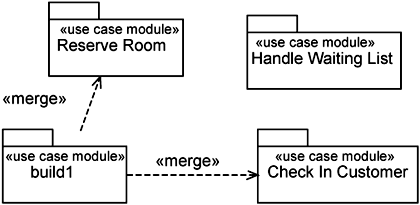
After working on individual use-case modules, you compose them into the desired build. Suppose we allocate three use-case modules targeted for delivery in one build. We have a composite use-case module called build1, which is the result of merging the three use-case modules, as shown in Figure 10-7. The UML package «merge» dependency in Figure 10-7 depicts the composition of use-case modules.
The relationships between use-case modules govern how they are composed to form the desired build. When you compose or merge use-case modules, you compose all the corresponding slices within them.
Suppose, for some reason, the Handle Waiting List «use case module», which is responsible for the Handle Waiting List use case, is extremely buggy. Naturally, we do not want to release this defective use-case module at the end of the iteration. All we need to do is remove it from our build, and the actual build is build2, as depicted in Figure 10-8. Since the use-case module is not composed into build2, none of the extensions owned by the Handle Waiting List «use case module» will be compiled into build2. It is as if it was not developed in the first place. So, you can release build2 to the stakeholders while you use build1 to do further debugging and testing.
In general, you can mix and match versions of use-case modules at will to yield a desired build. If, on the other hand, you were to use the traditional modularity approach (classes alone), you must have the developers work on classes and add code fragments directly to existing classes, making them extremely cluttered. Suppose there are some defects and you want to remove those code fragments that belong to the defective use case. This is a practical impossibility because it means that you must go to individual classes and undo the work being done. What usually happens is that developers simply leave the dead codes within the system. This adds to the tangling within the existing classes and potentially introduces more bugs.
As a quick recap, software development is about building models. At the beginning of a project, you have to choose a set of models that adequately describe the system. Each model has its own language and constructs to describe the system from that modeling perspective, and in addition, there are relationships between constructs from one model to another to help maintain consistency among models and to guide the derivation of model elements downstream.
You do not build a system model by model, but rather use-case module by use-case module. Use-case modules are units of software development effort. They localize the elements from different models related to a single use case in a single package. They are developed independently and iteratively. In fact, in Part IV of the book, each chapter is formulated in this way. Each chapter takes a use case and walks through all the activities about that use case, from requirements to code.


