
A system ultimately needs to execute on a target platform, so at some point in time, you must incorporate platform specifics into your design. This work is often repetitive, as platform specifics cut across many use cases. You want to be shielded from changes in the platform, since this affects many parts of the system. You want to introduce specifics as late as possible without ever doing anything twice. In this chapter, we demonstrate how this is achieved using the J2EE platform as an example. In particular, we show how processing tiers—presentation tier, business tier, and integration tier—are modeled as parameterized infrastructure use cases. These are subsequently mapped into parameterized use-case slices, which are overlaid on existing, platform-independent use-case slices. We demonstrate not only how you can keep platform specifics separate, but also how you apply both aspect orientation and architectural frameworks side by side. After all, both are techniques to achieve separation of concerns, and in a typical project, you need to apply both of them.
Up to this point, we have discussed the realization of use cases (application or infrastructure) deliberately from a platform-independent perspective because our intent is indeed to keep platform specifics separate. Nevertheless, at some point in time, you must deal with them and incorporate them into each use-case slice.
Incorporating platform specifics into each use case is achieved is by treating each platform-specific concern as a special kind of infrastructure use case. As in the case of infrastructure use cases, discussed in Chapter 14, “Separating Nonfunctional Requirements with Infrastructure Use Cases,” you design the platform specific use case generically with reference to a 〈Perform Transaction〉 use-case pattern. This yields a use-case slice pattern template. You then apply the pattern template on the existing use-case slices as needed.
Keeping platform specifics separate in this way is extremely beneficial if your team has designated specialists in each platform-specific area (security, distribution, user interfaces, etc.): you can have these specialists work on the platform-specific slices separately from other use cases.
Today, many systems are distributed according to a three-tier structure such that the presentation logic, business logic, and integration logic can be neatly separated. However, components no longer communicate directly over a programming interface, but over the network through some communication interface. This makes the implementation of the system significantly more complicated. A developer must understand not only what the application needs to do, but also the low-level details of such distribution mechanisms. It is a great benefit to keep such platform specifics separate from the realization of application use cases. In this chapter, we demonstrate how this can be achieved through a special kind of infrastructure use case—one that introduces processing tiers into the system.
We use the Java 2 Platform Enterprise Edition (J2EE) to demonstrate how to keep platform specifics separate from application-use-case realizations. J2EE comprises a set of technologies to perform session management, object management, communication, persistency, and other tasks. It is widely adopted by many organizations, and much literature has been devoted to it. One of the most important works that provides best practices and recommendations on the appropriate use of J2EE is documented in Core J2EE Patterns [Alur et al.]. It categorizes design patterns according to the above mentioned tiers.
The presentation tier encapsulates all presentation logic required to service the clients that access the system. It intercepts the client requests and provides authorization and session management. It controls access to the business services and delivers responses to the client. The main technologies in this layer are servlets and Java Server Pages (JSPs). Servlets and JSPs are themselves not user interface elements, but they do generate user interface elements such as HTML that are rendered on client browsers.
The business tier encapsulates business services required by the application clients. It contains the business data and business logic. Usually, most business processing for the system is centralized into this tier. The main technology in this tier is Enterprise Java Beans (EJBs).
The integration tier is responsible for communicating with external resources and systems such as databases and legacy systems. The main technologies in this tier are Java DataBase Connectivity (JDBC) and J2EE Connector to integrate with legacy systems.
In this chapter, we discuss how the specifics in each tier are overlaid on top of minimal use-case design. We also provide examples to demonstrate different techniques to design slices, and we demonstrate how aspect orientation and object-oriented frameworks such as J2EE can coexist. This is important because you will likely be developing systems that use a combination of these techniques. After all, both are techniques to achieve separation of concerns, and you must find a balance between the two.
In the discussion that follows, we describe some of the J2EE core patterns and demonstrate how they are designed as parameterized use-case slices. Specifically, the J2EE core patterns help to identify the parameters in these slices. Our discussion on the J2EE core patterns is brief, since this is not an AspectJ, Java, or J2EE book. If you want to know more about J2EE and the J2EE core patterns, we suggest that you refer to the relevant literature [Alur et al.].
In the previous chapters, we described how to identify the contents of the app package: The analysis classes (boundary, control, and entity) are mapped into design boundary, control, and entity. These design elements are meant to have minimal platform specifics. In Java, they are known as POJOs—Plain Old Java Objects. These classes are located in the app package of each design package (see Figure 15-1).
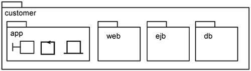
With the incorporation of distribution (i.e., the various tiers identified above), you need additional classes, which are application-dependent. For example, you need a class to handle Web requests for a use case; you need a class to provide distribution of a control class; or you need a class to access the database. Thus, while these classes are application-dependent, they are not POJOs. Instead, they must make calls to the underlying middleware. To keep these classes separate from the minimal design app package, we create one package for each tier. We call them tier packages. A tier package represents a subset of a logical tier in the design model, such as web, ejb, and db, as shown in Figure 15-1. A tier package is both application- and platform-specific. The Web tier package contains elements to provide classes to introduce Web presentation for a use case. The ejb tier package contains elements to support EJB-based distribution for a use case. The db tier package contains elements to support persistency, such as accessing a relational database or an XML datastore for a use case.
We named the tier packages web, ejb, and db within Figure 15-1. This is just one way of naming tier packages. If there are more tiers in your system, you may have more tier packages.
We have established that there is a need for tier packages to organize the design elements. So, how do we find these design elements? The way to achieve this is to start with use cases—what are the use cases for each tier? What is the value the tier brings? From this use case, you can then start to identify classes, find the responsibilities of these classes, and so on.
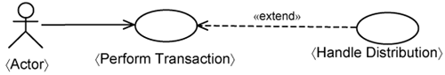
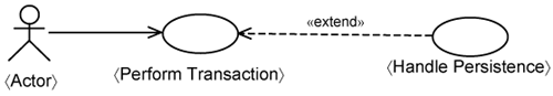
The top of Figure 15-2 shows the infrastructure use cases for each processing tier. They are all modeled as extensions to the 〈Perform Transaction〉 use-case template. In Figure 15-2, there is one infrastructure use-case template per tier: the 〈Handle Presentation〉 template use case, the 〈Handle Distribution〉 template use case, and the 〈Handle Persistence〉 template use case.
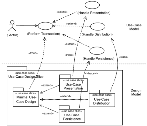
In essence, each infrastructure use case extends the base 〈Perform Transaction〉 use-case template with the specifics of a processing tier. The concerns of the 〈Perform Transaction〉 use case is kept separate from platform specifics. In Chapter 11, “Road to a Resilient Architecture,” we introduced the concept of a minimal use-case design slice. The contents of a minimal use-case slice adhere to the realization of the 〈Perform Transaction〉 use case. The other slices keep the concerns of each tier separate. The use-case presentation slice keeps the presentation behaviors specific to a use case separate. The use-case distribution slice keeps the distribution behaviors specific to a use case separate. The use-case persistence slice keeps the persistence behaviors specific to a use case separate. Thus, you have one of these use-case slices for each use case.
In the remainder of this chapter, we discuss each infrastructure use case in Figure 15-2. For each of them, we briefly describe the use case, and we describe two realizations—one without the infrastructure use case, the base 〈Perform Transaction〉 use-case template—and another one with the incorporation of the infrastructure use-case pattern. Thereafter, we describe how you apply the infrastructure use-case pattern.
Let us look at how you can incorporate user interface specifics (i.e., the Web tier in this case) onto the minimal use-case design slices. We begin with the 〈Handle Presentation〉 use case, depicted in Figure 15-3.
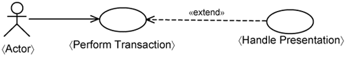
Listing 15-1 briefly describes the 〈Handle Presentation〉 use case. The binding of the 〈Handle Presentation〉 use case cannot be instantiated directly. It is a pure extension. It has an extension flow to introduce presentation specifics into the 〈Perform Transaction〉 use case.
Example 15-1. Brief Description of 〈Handle Presentation〉 Use Case
Extension Flow: 〈Handle Presentation〉
This extension flow occurs at each step of the 〈Perform Transaction〉 use case whenever the actor submits a request. The system gets the correct handler to service the request. The system generates an HTML output.
Alternate Flows
A1. Handle submission from different browsers.
A2. Handle long requests.
Listing 15-1 further shows an example of an alternate flow, which in this case is to handle the specifics of different browsers. There will likely be other alternate flows, such as handling requests with long service times by displaying a “please wait” message. You will likely find other alternative flows or special requirements of the 〈Handle Presentation〉 use case. However, we do not go into such details but proceed with the discussion on how to keep presentation specifics separate.
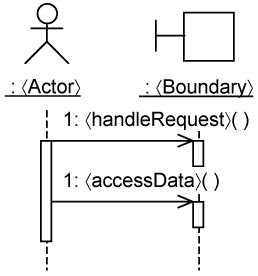
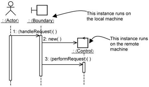
In the minimal use-case design, user interaction is encapsulated within boundary classes. A 〈Boundary〉 instance handles requests from the 〈Actor〉 instance, as shown in Figure 15-4. Request handling is often delegated to a control class, which is not shown in Figure 15-4 for brevity. In addition, the 〈Boundary〉 instance holds in itself temporary data values. These temporary values can be accessed by the 〈Actor〉 instance for displaying. Thus, a 〈Boundary〉 class provides two kinds of operations to the 〈Actor〉, collectively represented as 〈handleRequest〉 and 〈access-Data〉 in Figure 15-4.
When designing and implementing the 〈Boundary〉 class, you create a simple test-case instance to invoke it. The test case plays the role of the actor. This follows the concept of test-first design, which we discuss in greater detail in Chapter 16, “Separating Tests with Use-Case Test Slices.” Developing the 〈Boundary〉 class in this way helps you identify in detail the operations needed in the 〈Boundary〉 class as well as their parameters.
If you want to incorporate an actual user interface, you need user interface elements on top of the minimal use-case design. Additional classes are also needed by the user interface framework. For example, if you want the user interface to be Web-based, you need additional classes to execute the boundary class on a Web server. You also need classes to generate the actual Web display (i.e., HTML pages). In the J2EE core patterns, the Front Controller pattern provides the recommendations on how to design the Web-presentation mechanism. Specifically, it helps you to identify the classes needed and the interaction between their instances to realize the Web user interface. The typical interaction between the participating instances is shown in Figure 15-5.
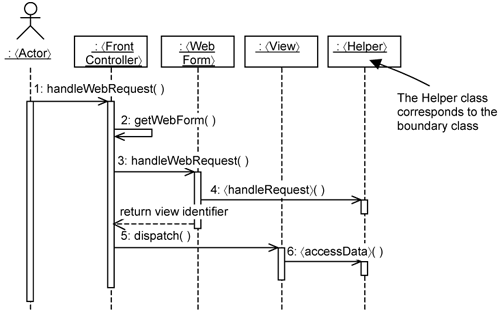
As you can see, instead of having one boundary class in the minimal use-case design (see Figure 15-4), there are now four classes in the Web presentation mechanism (see Figure 15-5). Each class deals with a particular concern and has a distinct set of responsibilities.
Briefly, the interaction in Figure 15-5 is as follows. The user, through the browser, sends Web requests (specifically, HTTP requests) to the Web server. Upon receiving the request, the Web server invokes the 〈FrontController〉. Thus, the 〈FrontController〉 is the very first contact from the outside world to the system. It is responsible for finding an appropriate WebForm to handleWebRequest().
The 〈FrontController〉 is implemented as a servlet in this case. The Web server knows the existence of the 〈FrontController〉 class through an XML configuration file known as a deployment descriptor.
The 〈WebForm〉 is responsible for extracting the parameters from the HTTP request and converting them to data objects. The 〈WebForm〉 then delegates the actual handling of the request to the 〈Helper〉 instance. The 〈Helper〉 is a POJO. It corresponds to the 〈Boundary〉 class. It makes no references to HTTP requests but works on the data objects passed in by the 〈WebForm〉. All HTTP request-related processing is localized to the 〈WebForm〉 class.
After handling the request (e.g., reserving a room, querying the reservation status), the 〈WebForm〉 returns an identifier indicating which 〈View〉 must be displayed. The 〈View〉 instance accesses the data from the 〈Helper〉 instance and display them. This 〈View〉 instance is responsible for all the work in generating HTML content.
We now design the use-case slice for the Web presentation mechanism. In designing the presentation mechanism, you have to keep separate:
that which is specific to the minimal use-case design.
that which is specific to the presentation of that use case.
that which is common across the presentation of any use cases.
Accordingly, there are three slices: the Minimal Use-Case Design slice, the Use-Case Presentation slice, and the Presentation slice. These slices are depicted in Figure 15-6. For generality, we model the use-case presentation slice as a parameterized use-case slice. The parameters must be substituted when you apply the slice on a specific use case.
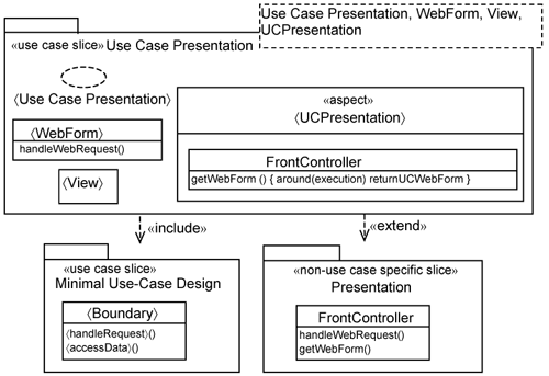
The Minimal Use-Case Design slice is the result of refining the use-case analysis. It contains boundary, control, and entity classes and aspects that are specific to the use case. Since in this case we are only interested in user interaction, only the 〈Boundary〉 class is shown. The 〈Boundary〉 corresponds to the 〈Helper〉 class discussed earlier.
The presentation slice is non-use-case-specific and contains classes that are common across the presentation of any use case. Specifically, it contains the FrontController class, which is shared by many use cases. It is the first point of contact for the system when the system receives a Web request. The FrontController needs to find the correct 〈WebForm〉 to service the request through the getWebForm() operation. Consequently, the getWebForm() has many operation extensions containing if-statements to determine which 〈WebForm〉 will indeed handle the request. These operation extensions are use-case-specific and will be overlaid by the Use-Case presentation slice.
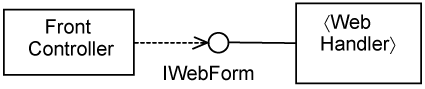
The use-case presentation slice contains a 〈WebForm〉 and one or more 〈View〉s that are specific to the presentation of a use case. All 〈WebForm〉s should conform to the same interface. In this case, let’s assume that they conform to the IWebForm interface. This interface is not shown in Figure 15-6 for brevity. We depict the IWebForm in Figure 15-7.
There is also a 〈UCPresentation〉 aspect to add the operation extension to the FrontController to forward the request to the 〈WebForm〉. The declaration for the operation extension is as follows:
getWebForm() { around (execution) returnUCWebForm }
It means that in the getWebForm(), you will have an operation extension returnUCWebForm. This operation extension determines which use case is being requested through the HTTP request parameters and returns the appropriate 〈WebForm〉.
The use-case presentation slice also contains a collaboration parameterized as 〈Use Case Presentation〉 to describe the interaction between user interface elements (e.g., views and Web handlers).
What we just achieved in the previous section is a template use-case slice for the presentation of a use case. To apply the template use-case slice, you need to substitute the parameters with actual classes and aspects. Figure 15-8 shows the result after applying the template use-case slice for the Reserve Room use case. The result is the Reserve Room Presentation use-case slice.
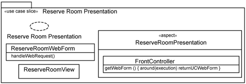
In Figure 15-8, the following substitutions are made:
The
〈Use Case Presentation〉〈Perform Transaction〉collaboration parameter is replaced byReserveRoomPresentationcollaboration. It describes the interaction between user interface elements that are involved in the Reserve Room use case.The
〈WebForm〉class parameter is replaced by theReserveRoomWebForm. This class is responsible for extracting HTTP request parameters.The
〈UCPresentation〉aspect parameter is replaced by theReserveRoomPresentationaspect. It contains an operation extension that will be overlaid onto the commonFrontControllerso that requests from users can be forwarded to theReserveRoomWebForm.You also need one or more views to display HTML results. You can create one view per Web request. Alternately, you can consolidate all requests into a single view, which is the case depicted in Figure 15-8. The strategy you choose is project-specific and is outside the scope of this book.
When you design user interfaces, you usually do not do so one use case at a time. Instead, you consider many use cases at once. Frequently, you must consider all the use cases associated with a specific actor. By taking the perspective of an actor, you have a better appreciation of the usability requirements—that is, what navigability is needed and what user interface elements are needed. Accordingly, you also design and implement user interfaces for many use cases at once. You will likely then incorporate use-case presentation slices for these different use cases together.
Distribution helps you improve the scalability and reliability of the system, but it does not add any functionality to the system. To the developer, incorporating distribution is one of the most repetitive tasks when developing an application. If there is a means to generate all the codes related to distribution, you can reduce such laborious work. You make this possible by keeping all distribution-related codes separate. If you ever need to modify the distribution mechanism, all you need do is regenerate the codes. Since use-case slices help you keep the codes separate, there is no worry about overwriting the work you have done.
Let us look at how you can incorporate distribution (i.e., EJB distribution in this case) onto the minimal use-case design slices. This is modeled in the use-case model through the 〈Handle Distribution〉 use case, as shown in Figure 15-9.
Listing 15-2 briefly describes the 〈Handle Distribution〉 use case. It is a pure extension use case as in the case of the 〈Handle Presentation〉 use case. The extension flow for the 〈Handle Distribution〉 use case essentially relays a local call to a remote machine. The alternate flows handle cases when the remote machine is not available.
Example 15-2. Brief Description of 〈Handle Distribution〉 Use Case
Extension Flow: 〈Handle Distribution〉
This extension flow occurs at each step of the application use case. For each call to a remote machine, this use case intercepts the call from the caller and relays the call over the network. When the remote call completes, the base use case resumes.
Alternate Flows
A1. Handle remote machine unavailability.
You will expect to find alternate flows in the 〈Handle Distribution〉 use case. Listing 15-2 provides an example for handling remote machine unavailability. There can be more alternative flows.
Let us now look at how you can incorporate distribution into use-case design. During analysis, you assume that instances reside in one process space and communication is via direct calls. During minimal use-case design, you have some idea which class you want to distribute. For example, you might decide to distribute the control class into a separate machine. Note that in general you can distribute any class, boundary, control, or entity. But for the purpose of discussion, we have chosen to distribute the control class. The same principle works for any class you want to distribute.
The usual interaction between the boundary class and the control class is depicted in Figure 15-10.
In general, there are two kinds of operations that the boundary instance might perform on the control instance:
Creating a control instance, such as through the
newoperation in Figure 15-10.Invoking a normal operation, such as
makeReservationon theReserveRoomHandlerinstance in the case of the Reserve Room use case (see the discussion of the realization of the Reserve Room use case in Section 12.1).
Since you are now distributing the control instance to a remote machine, you must intercept all these operation calls and replace them with remote calls.
Aspects do not provide any support for making remote calls and they do not create and manage remote instances for you. Aspects are just a general-purpose mechanism to provide the means to add behaviors to existing classes only. You must use some kind of middleware services to create and manage remote instances.
J2EE provides EJBs to help you create and manage remote instances. EJBs execute in what is called an EJB container. An EJB exposes two interfaces, a home interface and a remote interface:
Through the home interface, a client can create a remote EJB instance.
Through the remote interface, a client can invoke the remote EJB instance.
Recall that you want to distribute the control class (Figure 15-10) to a machine separate from that of the boundary class. You can wrap the control class within an EJB. To create an instance of the control class, you invoke the home interface on this wrapper EJB. You make a call to a control instance through the remote interface of this same EJB.
Next, you must intercept calls from the boundary class and replace it with calls to some proxy class. This proxy class uses the EJB services to call the control class through the wrapper EJB.
The J2EE core patterns provide a set of patterns to allow a 〈BusinessClient〉 instance on one machine to interact with a 〈BusinessService〉 instance on a remote machine. The 〈BusinessClient〉 and 〈BusinessService〉 correspond to 〈Boundary〉 and 〈Control〉 classes, respectively, in our minimal use-case design case above. Additional classes are involved to provide EJB distribution. They are based on the Business Delegate, Service Locator, and Session Facade patterns in the J2EE core patterns, as shown in Figure 15-11. We describe what each of these is responsible for. The vertical dashed lines in Figure 15-11 indicates which instances execute on the local machine and which instances execute on the remote machine.
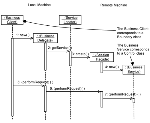
The purpose of the 〈BusinessDelegate〉 is to shield the fact that the 〈BusinessService〉 actually executes on a remote machine. It is the proxy class we mentioned earlier. The role of the 〈ServiceLocator〉 is to hide the details of the network structure (location and names of nodes, etc.) from the 〈BusinessDelegate〉. Both the 〈BusinessDelegate〉 and the 〈ServiceLocator〉 execute on the local machine. The 〈SessionFacade〉 executes on the remote machine and is the wrapper EJB we mentioned earlier.
Recall in the minimal use-case design, the 〈Control〉 class provides two kinds of operations: new() to create an instance of the 〈Control〉 class and 〈performRequest〉 to invoke some functionality on a 〈Control〉 instance. These two operations are refined by operations named the same way in the EJB distribution mechanism depicted in Figure 15-11.
A 〈BusinessClient〉 creates a 〈BusinessService〉 instance by first creating a 〈BusinessDelegate〉 locally. The 〈BusinessDelegate〉 makes use of the 〈ServiceLocator〉 to locate the 〈SessionFacade〉 in the network. Basically, this means getting the IP address and name of the 〈SessionFacade〉. The EJB container (i.e., the underlying J2EE platform) creates an instance of the 〈SessionFacade〉, which then creates an instance of the 〈BusinessService〉. The reference to the 〈SessionFacade〉 is returned to the 〈BusinessDelegate〉.
A 〈Business Client〉 makes a call to a 〈BusinessService〉 instance through a series of calls all named 〈performRequest〉 in Figure 15-11. Even though the name is the same, each class deals with it differently. They collaborate together to hand over the call from the local machine to the remote machine where the 〈BusinessService〉 is located.
As mentioned, the 〈BusinessDelegate〉 shields the fact that the 〈BusinessService〉 is actually executing on a remote machine. So, if there are any network-related exceptions—for example, if the remote machine is not available or has restarted—it will handle them. The 〈BusinessDelegate〉 has a reference to the desired 〈SessionFacade〉 instance. The 〈BusinessDelegate〉 call the 〈SessionFacade〉, which then calls the 〈BusinessService〉 instance. The 〈SessionFacade〉 is implemented as an EJB and, therefore, can use the underlying EJB platform to manage its instances in memory. The 〈SessionFacade〉 in this case encapsulates all EJB specifics on the remote machine from the 〈BusinessService〉. Thus, the 〈BusinessService〉 (i.e., the 〈Control〉 class) only needs to be a POJO.
Since communications between instances are over the network, you need to serialize data into byte streams. These data elements being passed around as byte streams are known as Transfer Objects (TOs). In Java, serialization is achieved simply by making data classes implementing a Serializable interface. This Serializable interface is part of the Java platform. Basically, by implementing this interface, the Java compiler is able to convert each Transfer Object into a byte stream, and vice versa.
Let’s consider how you can design the EJB distribution mechanism as a use-case distribution slice to keep distribution specifics separate from the Minimal Use-Case Design slice. To achieve this, the use-case distribution slice must do the following:
Intercept calls from a
〈Boundary〉instance to a〈Control〉instance and replace it with remote calls for both the creation of the〈Control〉instance and the invocation of any other operation on the〈Control〉instance.Hide all exceptions (such as remote machine not available, etc.) that are due to distributing the control class.
Figure 15-12 illustrates how we achieve this. At the top of Figure 15-12, we have the classes that are in the Minimal Use-Case Design slice. There is a 〈Boundary〉 class and a 〈Control〉 class. In addition, there is a data class 〈TransferObject〉 whose instances get passed as parameters in operation calls.
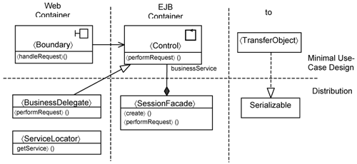
Figure 15-12 further separates the classes according to the containers they execute within. The 〈Boundary〉 class will be executing in the Web container. The 〈Control〉 class will be executing within the EJB container. The 〈TransferObject〉 is just something that gets passed around between the 〈Boundary〉 class and the 〈Control〉 class and between the Web container and the EJB container. Hence, it needs to realize the Serializable interface.
At the bottom, you see the classes that are needed to provide distribution. On the Web container, we have the 〈BusinessDelegate〉 and the 〈ServiceLocator〉. We have taken the approach to make 〈BusinessDelegate〉 a specialization of the 〈Control〉 class. Calls to create the 〈Control〉 instances are intercepted, which means you need to identify a pointcut for that. We return the 〈BusinessDelegate〉, which is a child of the 〈Control〉 class. In this way, we are substituting a 〈Control〉 instance with a 〈BusinessDelegate〉 instance.
The benefit of this approach is that you no longer need to intercept other calls from the 〈Boundary〉 to the 〈Control〉 using pointcuts and advices. Instead, you intercept calls through the inheritance mechanism. All you need to do is specialize each operation in the Control instance with a remote call to that operation. Thus, you are using the inheritance mechanisms to intercept calls rather than using the pointcut mechanism in AOP. Inheritance is much simpler than identifying pointcuts. Each operation in 〈BusinessDelegate〉 shields exceptions due to distribution from the 〈Boundary〉 class.
The 〈SessionFacade〉 holds a reference to the 〈Control〉, which plays the role of a business service. Each operation in 〈SessionFacade〉 invokes a corresponding operation in the 〈Control〉 class.
Because the developer of the 〈Boundary〉 class and the 〈Control〉 class—that is, the minimal use-case design—is aware that these classes run within separate processes (i.e., the Web and the EJB container), he or she will try to reduce the number of calls between the 〈Boundary〉 class and the 〈Control〉. Thus, the minimal use-case designs do take into account some distribution considerations. Nevertheless, this is just a guideline to the developer. Other than such guidelines, he or she will not have any EJB-related codes in the 〈Boundary〉 and 〈Control〉 classes. They are just POJOs.
All EJB-related code will be in the classes at the bottom of Figure 15-12. As per Figure 15-10, the 〈Boundary〉 class makes a direct call to the 〈Control〉 class. But this must be intercepted by a use-case distribution slice, as you shall see shortly. So, what you achieve is better modularity and separation of concerns. The minimal use-case design has no EJB-related code whatsoever. In addition, you design the use-case distribution slice as a template. This allows you to apply the use-case distribution repeatedly in a consistent manner.
Some parts of the distribution mechanism will be common across the distribution of any use case and separated into a distribution slice.
Accordingly, you will have three use cases, as shown in Figure 15-13: the Minimal Use-Case Design slice, the Use-Case Distribution slice, and the distribution slice.
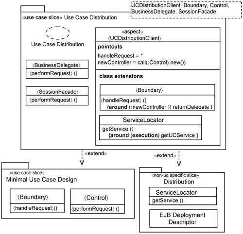
As mentioned, the Minimal Use-Case Design slice contains the specifics to realize use-case flow of events. It does not have any distribution design at all. The 〈Boundary〉 class and the 〈Control〉 class correspond to the 〈BusinessClient〉 and the 〈BusinessService〉, respectively.
The distribution slice is a non-use-case-specific slice. It contains the ServiceLocator for the system. In this example, we use one ServiceLocator for all use cases.
The distribution slice has also an EJB deployment descriptor, which is an XML file that identifies the EJBs (i.e., the SessionFacades) in the system. This allows the EJB container to locate and manage EJBs.
You can categorize the contents of the use-case distribution slice into whether it will execute on the Web container (i.e., the client) or the EJB container (i.e., the server), or is shared by the two.
The 〈BusinessDelegate〉 executes on the Web container. The 〈UCDistributionClient〉 aspect intercepts calls made by the 〈Boundary〉 class to create a 〈Control〉 instance on the client and returns the 〈BusinessDelegate〉. The 〈UCDistributionClient〉 aspect also adds operation extensions into the ServiceLocator to return the 〈SessionFacade〉 for the use case. The 〈SessionFacade〉 executes on the EJB container. You need to have home and remote interfaces for the 〈SessionFacade〉. For brevity, we do not show them in Figure 15-13.
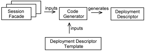
Each use-case distribution slice must add a small XML extension into the EJB deployment descriptor to indicate the existence of its EJBs (i.e., the SessionFacades) in the use-case distribution slice. Since AspectJ is only designed for Java, it is unable to add extensions to XML files. You need a different technology to do that. Today, a number of code-generation tools are available for you to achieve this. They range from open source utilities to commercial code generation tools.
Figure 15-14 shows how code-generation tools are used to generate EJB deployment descriptors. Basically, the code generator accepts a number of SessionFacades (which are implemented as EJBs) as inputs. This can be achieved either by parsing the source codes of the EJBs or through some other means of defining EJBs. The SessionFacades become parameters that are applied on the deployment descriptor template to generate the desired deployment descriptor. Thus, in effect, the code generator merges multiple EJB definitions into a single EJB deployment descriptor.
You can model what these code generators do as shown in Figure 15-15. We take the same approach of overlaying a use-case slice on a non-use-case-specific slice. After all, we are, in reality, overlaying an XML extension onto an XML file (the deployment descriptor). Figure 15-15 models the deployment descriptor as a classifier stereotyped as «deployment descriptor».
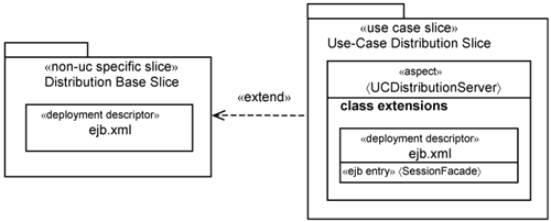
Each entry for an EJB description in the deployment descriptor is modeled as an attribute stereotyped as «ejb entry». In Figure 15-15, the name of the descriptor is ejb.xml. Through an additional 〈UCDistributionServer〉 aspect, the use-case distribution slice overlays the XML extension onto the deployment descriptor in the distribution slice. We model the XML extension as a class extension—special kind of class extension—which also resides in the class extensions compartment of the 〈UCDistributionServer〉 aspect.
So, indeed, you add two aspects: one 〈UCDistributionClient〉 aspect on the Web container and one 〈UCDistributionServer〉 aspect on the EJB container. But both aspects are part of the use-case distribution slice. As you can see, the use-case distribution slice cuts across the process structure.
Recall in Figure 15-12 that the 〈TransferObject〉 needs to realize the Serializable interface to support distribution. You can get the 〈UCDistributionServer〉 aspect to overlay this relationship on top of the 〈TransferObject〉, but this is not a good idea. It is just a trivial addition that will lead to scattering of such relationships that are an integral part of 〈TransferObject〉s. This will make the 〈UCDistributionServer〉 aspect look like patchwork and is poor modularity. Since the developer knows that the 〈TransferObject〉 needs to be serialized anyway, a better approach would be to let this relationship be part of minimal use-case design.
Let us now look at how you can apply the use-case distribution slice template discussed above. This is achieved by simply substituting the template parameters with actual classes and aspects into the template. As an example, Figure 15-16 shows the Reserve Room distribution slice.
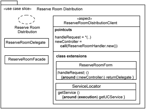
The Reserve Room distribution slice contains the following:
The
ReserveRoomDistributionClientaspect, which substitutes the〈UCDistributionClient〉parameter.The
ReserveRoomForm, which substitutes the〈Boundary〉parameter.The
ReserveRoomHandler, which substitutes the〈Control〉parameter.The
ReserveRoomDelegate, which substitutes the〈BusinessDelegate〉parameter.The
ReserveRoomFacade, which substitutes the〈SessionFacade〉parameter.
The template parameters 〈Boundary〉 and 〈TransferObject〉 are used in the contents of Distribution aspects and are substituted, respectively, by ReserveRoomForm and ReservationData. This allows the ReserveRoomDistributionClient aspect to intercept calls by the ReserveRoomForm to create a control class, and the ReserveRoomDistributionServer aspect to make the ReservationData serializable.
To make the discussion more concrete, Listing 15-3 shows the AspectJ source code for the ReserveRoomDistributionClient aspect.
Example 15-3. Source Code for ReserveRoomDistributionClient
1. public aspect ReserveRoomDistributionClient {
2.  pointcut newController() : within(ReserveRoomForm)
3.                      && call (ReserveRoomHandler.new(..)) ;
4.    ...
5.  ReserveRoomHandler around() : newController() {
6.    return new ReserveRoomDelegate() ;
7.  }
8.    ...
9. }
The newController pointcut in lines 2 and 3 refers to all operations in ReserveRoomForm that make calls to create a new ReserveRoomHandler instance. The advice in lines 5, 6, and 7 implements the operation extension:
handleRequest() {around (〈newController〉) returnDelegate }
It intercepts calls to create a new ReserveRoomHandler and returns a ReserveRoomDelegate instead.
The use-case distribution slice template looks much more complicated than the use-case presentation template, however, looks can be deceiving. Many of the parameters in use-case distribution slice template can be generated automatically because their implementation is similar across use cases. All you need to do is work out a code sample for one use-case distribution. Other use-case distribution slices can follow this code template. In fact, you can generate the entire Reserve Room distribution slice once you have implemented the use-case distribution slice.
This is unlike use-case presentation, where you need to do user interface design and add the implementation details on generating HTML content and extracting request parameters from the submitted requests.
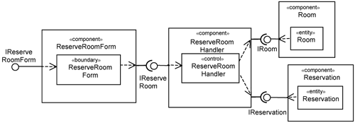
In Chapter 12, “Separating Functional Requirements with Peer Application Use Cases,” we described the ReserveRoomHandler component from the minimal design perspective. The left-hand side of Figure 15-17 shows the ReserveRoomHandler component prior to the overlaying of the use-case distribution slice. After overlaying the distribution slice, the ReserveRoomHandler component is endowed with additional classes and interfaces. The interfaces are depicted in the right-hand side of Figure 15-17.
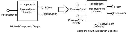
The contents of the ReserveRoomHandler component are depicted in Figure 15-18 using the notation in UML 2.0. The ReserveRoomHandler component has the three provided interfaces and two required interfaces.
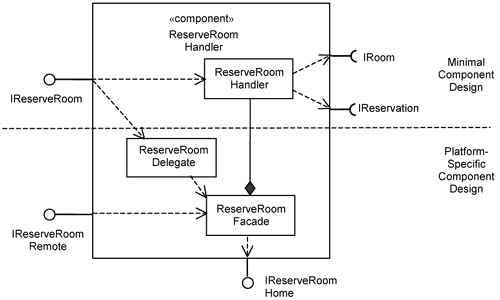
The horizontal line across Figure 15-18 separates the minimal component design from the platform-specific component design parts. The latter is overlaid onto the ReserveRoomHandler component through the use-case distribution slice.
The classes overlaid onto the ReserveRoomHandler component are the ReserveRoomDelegate and the ReserveRoomFacade. The platform-specific interfaces added are the IReserveRoomHome and IRemoteReserveRoom. The IReserveRoomHome is an EJB home interface. It is used by the EJB container to manage the EJBs (creating, pooling, etc.). The IRemoteReserveRoom permits clients to make calls over the network. Thus, you have three interfaces through which you make calls to the ReserveRoomHandler component:
IRemoteReserveRoom. TheIRemoteReserveRoominterface is a platform-specific interface to theReserveRoomHandlercomponent. It is an EJB remote interface. To make a call to this interface, the caller must be aware of the platform specifics (i.e., EJB distribution). This means creating theReserveRoomHandlercomponent remotely and so on.IReserveRoomHome. TheIReserveRoomHomeinterface is also a platform-specific interface to theReserveRoomHandlercomponent. It is an EJB home interface. It is used by the EJB distribution mechanism to create and manage instances of theReserveRoomHandlercomponent.IReserveRoom. TheIReserveRoominterface is a minimal design interface provided by theReserveRoomHandlercomponent. EJB distribution is hidden from callers to this interface.
The purpose of many systems, especially business systems, is to manage a set of information about customers and/or similar concerns. The Hotel Management System is one such example. It manages information about the hotel, and it automates a set of business processes. The use cases for this system are largely about accessing information about some persistent datastore. Consequently, a large part in the development of the system is about accessing the datastore. A change in the implementation specifics of the datastore often has a huge impact on the project.
Keeping the platform-specific persistence separate not only limits the impact of such changes, but also makes it possible to have early, useful testing in the beginning of a project. This is because you can now test the use case even when the persistent datastore has not been selected yet. Figure 15-19 shows the 〈Handle Persistence〉 use case as an extension of the 〈Perform Transaction〉 use case.
Listing 15-4 shows the 〈Handle Persistence〉 use-case specification. We kept it very simple and merely indicate that the system can access the datastore.
Example 15-4. Brief Description of 〈Handle Persistence 〉
Extension Flow: 〈Handle Persistence〉
This extension flow occurs at each step of the 〈Perform Transaction〉 use case whenever there is a need to access data from a datastore. The system accesses the datastore from the designated database.
Alternate Flows
A1. Handle datastore access concurrency.
Listing 15-4 also shows an example of an alternative flow, which is to handle access concurrency.
Let’s consider how you keep codes pertaining to persistence separate. Recall that the minimal use-case design assumes that data structures persist beyond the lifetime of entity instances; that is, the data structures remain in memory even when the entity instances are destroyed. This is illustrated in Figure 15-20, whereby the data structures labeled as ds are declared static (i.e., in memory). In UML, this is indicated with an underline. Thus, the underline beneath ds indicates that ds is a static attribute of the 〈Entity〉 class.
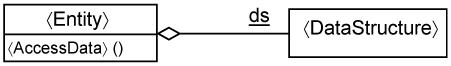
The advantage in using the minimal design entity class is that you can quickly proceed to design the data structures, code them, and evaluate the way you structure them. Does a particular structure have too many fields? Can you generalize the structure? What are the relationships between the structures? These questions are important because the data structure will need to be mapped into the actual datastore (possibly a relational database). Thus, this approach helps you kick-start database design. In addition, since you are able to go down to code quickly, you can define the operation parameters of your entity classes.
Note that putting all data elements in memory might not be something you would like to do when the system goes live. However, it provides a convenient way to test the boundary and control classes. Usually, when conducting tests, you need to ensure that the system under test is in some known initial state. If you are using an actual database, you must initialize it to a known state every time you run a test. This can be quite tedious and may take considerable time. Using the minimal use-case design, however, testing the use case is significantly simpler. All you need to do is initialize the static data structure in memory. Thus, this minimal design of the 〈Entity〉 class serves as a test stub. We talk more about testing in Chapter 16.
If you want to incorporate a persistency mechanism, you must substitute the 〈Entity〉 class with another one that is able to access data from a datastore (such as a relational database). Such a class is called a data access object (DAO) according to the J2EE core patterns. As the name implies, they are responsible for accessing data from a particular datastore using a particular data-access mechanism. DAOs hide all the specifics about that datastore or that mechanism from their callers, and if there are any changes to the way the datastore is structured, such changes will be encapsulated within the DAOs.
Recall that in minimal use-case design, the 〈Entity〉 class uses a static data structure in memory. But the actual system uses a real datastore. Thus, you need a way to decide which data-access class you need. Do you want the minimal 〈Entity〉 class or the actual DAO, which perhaps might access the actual relational database? This selection is made through a DAO Factory class. The purpose of this class is to return an appropriate DAO class based on the datastore type (see Figure 15-21).
In J2EE, the usual practice is for the DAOFactory to determine the type of DataAccessObject to be returned based on some environment variables provided by the execution platform (i.e., J2EE). Thus, by changing the environment variable, you can configure which data-access class to use, whether it is minimal use-case design 〈entity〉 class, or a class that accesses a real data store, be it a SQL datastore, an XML datastore, or other type of datastore.
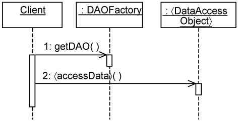
Let’s consider how you can apply the DAOFactory pattern on the minimal use-case design. Figure 15-22 shows the usual case of accessing data managed by 〈Entity〉 instances. The 〈Control〉 instance first creates an instance of the 〈Entity〉 and thereafter makes calls to 〈AccessData〉 in the 〈Entity〉 instance.
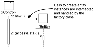
To introduce the DAOFactory pattern, you intercept the call to create instances of the 〈Entity〉 and call the DAOFactory instead. The DAOFactory determines whether to return the minimal use-case design 〈Entity〉 instance or a platform-specific DAO.
You can substitute an 〈Entity〉 instance with a 〈DataAccessObject〉 instance, but you still must design the 〈DataAccessObject〉. Today, relational databases are commonly used as a persistent datastore, and developers spend considerable time writing code to perform object-relational mappings. It is no wonder that many competing persistency frameworks are available. There are tools available even to generate code to perform data access from relational datastores. Although this is attractive, the problem is that they take a data-centric view and generate essential create, read, update, and delete operations for you. There are more sophisticated tools to generate even more of such code, but there will always be a need for some use-case-specific manipulation of records. Thus, you often need to supplement with additional codes to do just that. You can keep codes that perform use case specific manipulation within Use-Case Persistence slices.
You can put the use-case-generic part of persistency in an entity-persistent slice. You make this entity-persistent slice a template, since you want to take advantage of the available tools to generate the essential create, read, update, delete, and other operations.
You still have the usual Minimal Use-Case Design slice and a slice to hold what is common across the persistence of all entities (e.g., the DAOFactory). This results in four use-case slices: the Minimal Use-Case Design slice, the entity-persistence template slice, the persistence slice, and use-case persistence slice. The first three slices are shown in Figure 15-23.
As before, the minimal use-case design contains only the logic specific to the use case. It contains no platform-specific persistence contents. We show the 〈Control〉 class in Figure 15-23 to indicate that the behavior of the Control class will be modified by the use-case persistence slice.
The entity-persistence slice is different in nature from the use-case presentation and use-case distribution slices we discussed earlier. In the previous examples, these slices are applied on a per-use-case-design slice. However, you will have one entity-persistence slice per entity instead. This is because entity persistence is use-case-generic.
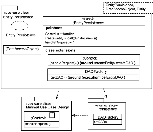
The entity-persistence slice contains an entity-persistence collaboration that describes the data-access mechanism used. The entity-persistence slice has three template parameters: the 〈EntityPersistence〉 aspect, the 〈DataAccessObject〉 class, and the name of the 〈Entity〉, which will be replaced by the 〈DataAccessObject〉. The name is used by the DAOFactory to return the appropriate DAO. Potentially, the DAOFactory is responsible for creating many DAOs, one set for each entity class.
The 〈EntityPersistence〉 aspect contains two class extensions. The first is a class extension for the 〈Control〉 class. In essence, this class extension intercepts calls to create 〈Entity〉 instances and replaces them with calls to the DAOFactory to return an appropriate DAO.
The 〈EntityPersistence〉 aspect contains several parameters implemented using the parameterization (i.e., regular expression) capability provided by AOP pointcuts. All three parameters are used in the 〈Control〉 class extension. The 〈Control〉 parameter is bound to any class whose name ends with Handler (i.e., the regular expression *Handler). The 〈handleRequest〉 parameter is bound to *, which means all operations. The parameter 〈createEntity〉 is bound to call (〈Entity〉.new()), which means to all calls to create a new 〈Entity〉 instance. So, collectively, they are used to intercept all operations within *Handlers that attempt to create a new 〈Entity〉 instance.
The second is a class extension for the DAOFactory class. This extension indicates the existence of the 〈DataAccessObject〉 defined in the entity-persistence slice.
The persistence slice contains the DAOFactory class to control which DAO is returned. In this example, there is one DAOFactory for the system.
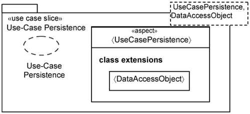
As the name implies, the use-case persistence slice provides the means for you to overlay use-case-specific data access operations. It is shown in Figure 15-24. It simply adds these operations through the 〈DataAccessObject〉 class extension.
You apply the entity-persistence template slice by substituting the template parameters. Figure 15-25 illustrates what happens when you apply the entity-persistence template slice on the Reservation entity class.
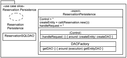
As mentioned, there is plenty of room for you to automatically generate the codes for the reservation-persistence slice, since it merely provides the usual create, read, update, and delete operations for the Reservation-SQLDAO.
The main idea is this: by separating what is use-case-specific and what is use-case-independent, you can automatically generate a lot of code that would otherwise take up much of your precious time. If you need more sophisticated data-access operations, you can then create a Use-Case Persistence slice.
In the preceding sections, we described how you can design the various tiers for the system. These tiers involve platform specifics, which you want to keep separate. Let’s compare how a use-case realization looks like before and after overlaying the platform specifics. Figure 15-26 depicts the realization of the Reserve Room use case from a minimal design perspective. Figure 15-27 depicts the same use-case realization after overlaying the presentation, distribution, and persistency slices.
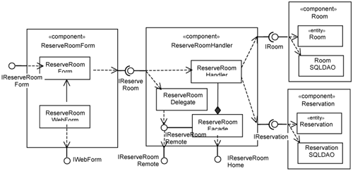
As can be seen from Figure 15-26, the minimal use-case design realization of a use case looks very similar to the use-case realization in analysis. Even after the incorporation of the platform specifics (see Figure 15-27), the components and the relationships between them still conform to what you have created during analysis. This illustrates what is meant by preserving the structure of the analysis model in design. It makes the design of the system more understandable than a design that does not attempt to preserve the analysis structure.
Within each component in Figure 15-27, we depict the minimal design classes (i.e., POJOs) at the top and classes that link the POJOs to the infrastructure below. In addition, the bottom of Figure 15-27 shows interfaces that are used to plug the components into the selected platform—in this case, J2EE. Depicting components in this way has several benefits. It helps the reader clearly distinguish which parts are:
use-case-specific
use-case-specific and platform-specific
platform-specific
This is precisely what a good architecture is about—keeping concerns separate. Frequently, the parts that are both use-case specific and platform specific can be automatically generated. This is yet another advantage for us to keep these different parts separate.
A significant portion of the code used to implement a typical system has to do with platform specifics. This usually means that the system becomes tightly coupled with the selected platform. In this chapter, we show how you can keep platform specifics separate through use-case slices. The advantages of doing so are many. First, you can easily replace the platform specifics by replacing the slices. Second, by keeping the platform specifics separate, you can quickly build and test the non-platform-specific parts of the system. In this way, you can quickly and objectively evaluate the platform-independent structure you have established in analysis.
In this chapter, we use templates extensively. The platform-specific parts of a use case are designed as template use-case slices (use-case presentation slice, use-case distribution slice, etc.). This makes incorporation of platform specifics simpler and more consistent because developers have a template to follow. More importantly, templates provide opportunities for significant automation. Tools and utilities are already available to generate codes based on code templates. This improves your team productivity dramatically.