
CHAPTER 13
Audio Interconnection
Analog signals can be conveyed from one device to another with relative ease, but the transfer of audio signals in the digital domain is a good deal more complex. Sampling frequency, word length, control and synchronization words, and coding must all be precisely defined to permit successful interfacing. Above all, the data format itself takes precedence over the physical medium or interconnection it happens to currently occupy. Numerous data formats have been devised to connect digital audio devices, both between equipment of the same manufacturer, and between equipment of different manufacturers. Using appropriate interconnection protocols, data can be conveyed in real time over long and short distances, using proprietary or open channel formats. Fiber-optic communication provides very high bandwidth and is particularly effective when data is directed over long distances. In many applications, files are transmitted in non-real-time; these file formats are described in Chap. 14.
Audio Interfaces
Perhaps the most fundamental interconnection in a studio is the connection of one hardware device to another, so that digital audio data can be conveyed between them in real time. Clearly, a digital connection is preferred over an analog connection; the former can be transparent, but the latter imposes degradation from digital-to-analog and analog-to-digital conversion.
To convey digital data, there must be both a data communications channel and common clock synchronization. One hard-wired connection can provide both functions, but as the number of devices increases, a separate master clock signal is recommended. In addition, the interconnection requires an audio format recognized by both transmitting and receiving devices. Data flow is usually unidirectional, directed point to point (as opposed to a networked or bus distribution), and runs continuously without handshaking. Perhaps two, or many audio channels, as well as auxiliary data, can be conveyed, usually in serial fashion. The data rate is determined by the signal’s sampling frequency, word length, number of channels, amount of auxiliary data, and modulation code. When the receiving device is a recorder, it can be placed in record mode, and in real time can copy the received data stream. Given correct operation, the received data will be a clone of the transmitted data.
One criterion for successful transmission of serial data over a coaxial cable is the cable’s attenuation at one-half the clock frequency of the transmitted signal. Very generally, the maximum length of a cable can be gauged by the length at which the cable attenuates the frequency of half the clock frequency by 30 dB. Professional interfaces can permit cable runs of 100 to 300 meters, but consumer cables might be limited to less than 10 meters. Fiber cables are much less affected by length loss and permit much longer cable runs. Examples of digital audio interfaces are: SDIF-2, AES3 (AES/EBU), S/PDIF, and AES10 (MADI).
SDIF-2 Interconnection
The SDIF-2 (Sony Digital InterFace) protocol is a single-channel interconnection protocol used in some professional digital products. For example, it allows digital transfer from recorder to recorder. A stereo interface uses two unbalanced BNC coaxial cables, one for each audio channel. In addition, there is a separate coaxial cable for word clock synchronization, a symmetrical square wave at the sampling frequency that is common to both channels. The word clock period is 22.676 μs at a 44.1-kHz sampling frequency, the same period as one transmitted 32-bit word. Any sampling frequency can be used. The signal is structured as a 32-bit word, as shown in Fig. 13.1. The most significant bit (MSB) through bit 20 are used for digital audio data, with MSB transmitted first, with nonreturn to zero (NRZ) coding. The data rate is 1.21 Mbps at a 44.1-kHz sampling frequency, and 1.53 Mbps at a 48-kHz sampling frequency.
When 16-bit samples are used, the remaining four bits are packed with binary 0s. Bits 21 through 29 form a control (or user) word. Bits 21 through 25 are held for future expansion; bits 26 and 27 hold an emphasis ID determined at the point of A/D conversion; bit 28 is the dubbing prohibition bit; and bit 29 is a block flag bit that signifies the beginning of an SDIF-2 block. Bits 30 through 32 form a synchronization pattern. This field is uniquely divided into two equal parts of 1.5T (one and one-half bit cell) forming a block synchronization pattern. The first word of a block contains a high-to-low pulse and the remaining 255 words have a low-to-high pulse.
This word structure is reserved for the first 32-bit word of each 256-word block. The digital audio data and synchronization pattern in subsequent words in a block are structured identically. However, the control field is replaced by user bits, nominally set to 0. The block flag bit is set to 1 at the start of each 256-word block. Internally, data is processed in parallel; however, it is transmitted and received serially through digital input/output (DI/O) ports. For two-channel operation, SDIF-2 is carried on a single-ended 75-Ω coaxial cable, as a transistor-transistor logic (TTL) compatible signal. To ensure proper operation, all three coaxial cables should be the same length. Some multitrack recorders use a balanced/differential version of SDIF-2 with RS-422-compatible signals. A twisted-pair ribbon cable is used, with 50-pin D-sub type connectors, in addition to a BNC word clock cable. The SDIF-2 interface was introduced by Sony Corporation.
Both SDIF-3 and MAC-DSD are used to convey DSD (Direct Stream Digital) audio data, as used in the Super Audio CD (SACD) disc format. SDIF-3 is an interface designed to carry DSD data. It conveys one channel of DSD audio per cable, and employs 75-Ω unbalanced coaxial cable and represents data in phase-modulated form (as opposed to DSD-raw, NRZ unmodulated form). A word clock of 44.1 kHz can be used for synchronization; alternatively, a 2.8224-MHz clock can be used. MAC-DSD (Multi-channel Audio Connection for DSD) is a multichannel interface for DSD data for professional applications. It uses twisted-pair Ethernet (100Base-TX using CAT-5 cabling terminating in 8-way RJ45 jacks and using a PHY physical layer interface) interconnection but it is used for point-to-point transfer rather than as a network node. MAC-DSD can transfer 24 channels of DSD audio in both directions simultaneously along with 64fs (2.8224 MHz) DSD sample clocks in both directions. Point-to-point latency is less than 45 μs. The PHY device transmits data in frames with a bit rate of 100 Mbps. Each frame is up to 1536 bytes with a 64-bit preamble and 96 bit-period interframe gap. User data is 1528 bytes and maximum bit rate is 98.7 Mbps; 24 channels of DSD audio yields a bit rate of 67.7 Mbps. Other capacity is used for error correction, frame headers, and auxiliary data. Audio data, control data, and check bits are interleaved in 32-bit blocks, one per DSD sample period. The structure of a MAC-DSD audio data frame is shown in Fig. 13.2. If multiple MAC-DSD links are used (for more than 24 channels) differences in latency are overcome with a 44.1-kHz synchronization signal. Connections between a source/destination device and a hub use standard CAT-5 cable such that pin-outs on hub devices are reversed to connect inputs to outputs. In peer-to-peer interconnections between two source/destination devices, a crossover cable is used such that pin-outs at one end are reversed to connect inputs to outputs. Unlike typical Ethernet cables, in these crossover cables both two data pairs and clock signal connections are reversed.
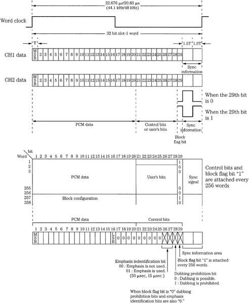
FIGURE 13.1 The SDIF-2 interface is used to interconnect digital audio devices. The control word conveys nonaudio data in the interface.
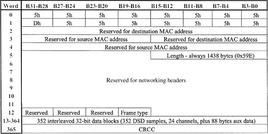
FIGURE 13.2 The structure of a MAC-DSD audio data frame. Audio data, control data, and check bits are interleaved within 32-bit data blocks. Each data block corresponds to a DSD sampling period.
AES3 (AES/EBU) Professional Interface
The Audio Engineering Society (AES) has established a standard interconnection generally known as the AES3 or AES/EBU digital interface. It is a serial transmission format for linearly represented digital audio data. It permits transmission of two-channel digital audio information, including both audio and nonaudio data, from one professional audio device to another. The specification provides flexibility within the defined standard for specialized applications; for example, it also supports multichannel audio and higher sampling frequencies. The format has been codified as the AES3-1992 standard; this is a revised version of the original AES3-1985 standard. In addition, other standards organizations have published substantially similar interface specifications: The International Electrotechnical Commission (IEC) IEC-60958 professional or broadcast use (known as type I) format, the International Radio Consultative Committee (CCIR) Rec. 647 (1990), the Electronic Industries Association of Japan (EIAJ) EIAJ CP-340-type I format, the American National Standards Institute (ANSI) ANSI S4.40-1985 standard, and the European Broadcasting Union (EBU) Tech. 3250-E.
The AES3 standard establishes a format for nominally conveying two channels of periodically sampled and uniformly quantized audio signals on a single twisted-pair wire. The format is intended to convey data over distances of up to 100 meters without equalization. Longer distances are possible with equalization. Left and right audio channels are multiplexed, and the channel is self-clocking and self-synchronizing. Because it is independent of sampling frequency, the format can be used with any sampling frequency; the audio data rate varies with the sampling frequency. A sampling frequency of 48 kHz ±10 parts per million is often used but 32, 44.1, 48, and 96 kHz are all recognized as standard sampling frequencies by the AES for pulse-code modulation (PCM) applications in standards document AES5-1998. Moreover, AES3 has provisions for sampling frequencies of 22.05, 24, 88.2, 96, 176.4, and 192 kHz. Sixty-four bits are conveyed in one sampling period; the period is thus 22.7 μs with a 44.1-kHz sampling frequency. AES3 alleviates polarity shifts between channels, channel imbalances, absolute polarity inversion, gain shifts, as well as analog transmission problems such as hum and noise pickups, and high-frequency loss. Furthermore, an AES3 data stream can identify monaural/stereo, use of pre-emphasis, and the sampling frequency of the signal.
The biphase mark code, a self-clocking code, is the binary frequency modulation channel code used to convey data over the AES3 interconnection. There is always a transition (high to low, or low to high) at the beginning of a bit interval. A binary 1 places another transition in the center of the interval; a binary 0 has no transition in the center. A transition at the start of every bit ensures that the bit clock rate can be recovered by the receiver. The code also minimizes low-frequency content, and is polarity-free (information lies in the timing of transitions, not their direction). All information is contained in the code’s transitions. Using the code, a properly encoded data stream will have no transition lengths greater than one data period (two cells), and no transition lengths shorter than one-half coding period (one cell). This kind of differential code can tolerate about twice as much noise as channels using threshold detection. However, its bandwidth is large, limiting channel rate; logical 1 message bits cause the channel frequency to equal the message bit rate. The overall bit rate is 64 times the sampling frequency; for example, it is 3.072 Mbps at a 48-kHz sampling frequency. Channel codes are discussed in Chap. 3.
AES3 Frame Structure
The AES3 specification defines a number of terms. An audio sample is a signal that has been periodically sampled, quantized, and digitally represented in a two’s complement manner. A subframe is a set of audio sample data with other auxiliary information. Two subframes, one for each channel, are transmitted within the sampling period; the first subframe is labeled 1 and the second is labeled 2. A frame is a sequence of two sub-frames; the rate of transmission of frames corresponds exactly to the sampling rate of the source. With stereo transmissions, subframe 1 contains left A-channel data and sub-frame 2 contains right B-channel data, as shown in Fig. 13.3A. For monaural, the rate remains at the two-channel rate, and the audio data is placed in subframe 1.
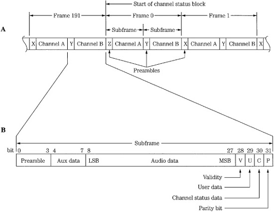
FIGURE 13.3 The professional AES3 serial interface is structured in frames and subframes as well as channel status blocks formed over 192 frames. A. There are two subframes per frame; each subframe is identified with a preamble. B. The interface uses a subframe of 32 bits.
A block is a group of channel status data bits and an optional group of user bits, one per subframe, collected over 192 source sample periods. A subframe preamble designates the starts of subframes and channel status blocks, and synchronizes and identifies audio channels. There are three types of preambles. Preamble Z identifies the start of subframe 1 and frame 0, which is also the start of a channel status block. Preamble X identifies the start of subframe 1 otherwise, and Preamble Y identifies the start of sub-frame 2. Preambles occupy four bits; they are formed by violating the biphase mark coding in specific ways. Preamble Z is 3UI/1UI/1UI/3UI where UI is a unit interval. Preamble X is 3UI/3UI/1UI/1UI. Preamble Y is 3UI/2UI/1UI/2UI.
The format specifies that a subframe has a length of 32 bits, with fields that are defined as shown in Fig. 13.3B. Audio data might occupy up to 24 bits. Data is linearly represented in two’s complement form, with the least significant bit (LSB) transmitted first. If the audio data does not require 24 bits, then the first four bits can be used as an auxiliary data sample, as defined in the channel status data. For example, broadcasters might use the four auxiliary bits for a low bit-rate talkback feed. When devices use 16-bit words, the last 16 bits in the data field are used, with the others set to 0. Four bits conclude the subframe: Bit V—An audio sample validity bit is 0 if the transmitted audio sample is error-free, and 1 if the sample is defective and not suitable for conversion to an analog signal. Bit U—A user data bit can optionally be used to convey blocks of user data. A recommended format for user data is defined in the AES18-1992 standard, as described below. Bit C—A channel status bit is used to form blocks describing information about the interconnection channel and other system parameters, as described below. Bit P—A subframe parity bit provides even parity for the subframe; the bit can detect when an odd number of errors have occurred in the transmission.
AES3 Channel Status Block
The audio channel status bit is used to convey a block of data 192 bits in length. An overview of the block is shown in Fig. 13.4. Received blocks of channel status data are accumulated from each of the subframes to yield two independent channel status data blocks, one for each channel. At a sampling frequency of 48 kHz, the blocks repeat at 4-ms intervals. Each channel status data block consists of 192 bits of data in 24 bytes, transmitted as one bit in each subframe, and collected from 192 successive frames. The block rate is 250 Hz at a 48-kHz sampling frequency. The channel status block is synchronized by the alternate subframe preamble occurring every 192 blocks.
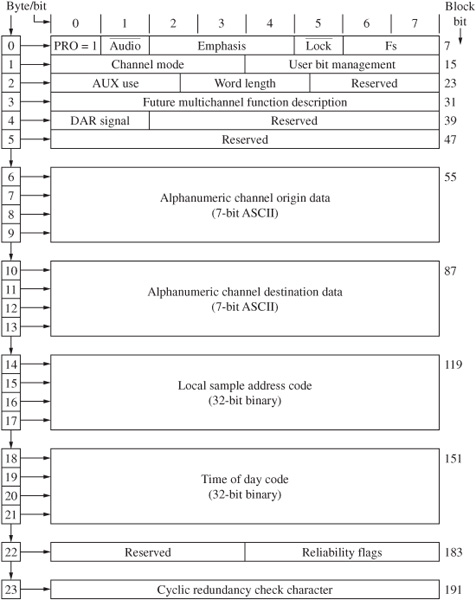
FIGURE 13.4 Specification of the 24-byte channel status block used in the AES3 serial interface.
There are 24 bytes of channel status data. The first six bytes (outlined at the top of Fig. 13.4) are detailed in Fig. 13.5. Byte 0 of the channel status block contains information that identifies the data for professional use, as well as information on sampling frequency and use of pre-emphasis. With any AES3 communication, bit 0 in byte 0 must be set to 1 to signify professional use of the channel status block. Byte 1 specifies the signal mode such as stereo, monaural, or multichannel. Byte 2 specifies the maximum audio word length and number of bits used in the word; an auxiliary coordination signal can be specified. Byte 3 is reserved for multichannel functions. Byte 4 identifies multichannel modes, type of digital audio reference signal (Grade 1 or 2) and alternative sampling frequencies. Byte 5 is reserved. Bytes 6 through 9 contain alphanumeric channel origin code, and bytes 10 through 13 contain alphanumeric destination code; these can be used to route a data stream to a destination, then display its origin at the receiver. Bytes 14 through 17 specify a 32-bit sample address. Bytes 18 through 21 specify a 32-bit time-of-day timecode with 4-ms intervals at a 48-kHz sampling frequency; this timecode can be divided to obtain video frames. Byte 22 contains data reliability flags for the channel status block, and indicates when an incomplete block is transmitted. The final byte, byte 23, contains a cyclic redundancy check code (CRCC) codeword with the generation polynomial x8 + x4 + x3 + x2 + 1 across the channel status block for error detection.
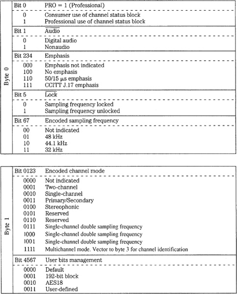
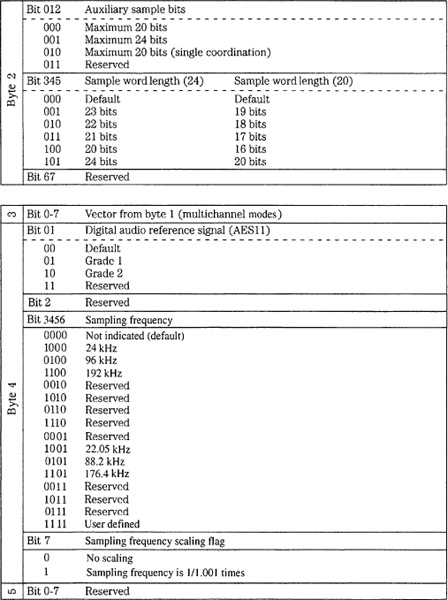
FIGURE 13.5 Description of the data contained in bytes 0 to 5 in the 24-byte channel status block used in the AES3 serial interface.
Three levels of channel status implementation are defined in the AES3 standard: minimum, standard, and enhanced. These establish the nature of the data directed to the receiving units. With the minimum level, the first bit of the channel status block is set to 1 to indicate professional status, and all other channel status bits are set to 0. With standard implementation, all channel status bits in bytes 0, 1, and 2 (used for sampling frequency, pre-emphasis, monaural/stereo, audio resolution, and so on) and CRCC data in byte 23 must be transmitted; this level is the most commonly used. With enhanced implementation, all channel status bits are used.
As noted, audio data can occupy 24 bits per sample. When the audio data occupies 20 bits or less, the four remaining bits can be optionally used as an auxiliary speech-quality coordination channel, providing a path so that verbal communication can accompany the audio data signal. Such a channel could use a sampling frequency that is 1/3 that of the main data rate, and use 12-bit coding; one 4-bit nibble is transmitted in each subframe. Complete words would be collected over three frames, providing two independent speech channels. The resolution of the main audio data must be identified by information in byte 2 of the channel status block.
AES3 Implementation
In many ways, in its practical usage an AES3 signal can be treated similarly to a video signal. The electrical parameters of the format follow those for balanced-voltage digital circuits as defined by the International Telegraph and Telephone Consultative Committee (CCITT) of the International Telecommunication Union (ITU) in Recommendation V.11. Driver and receiver chips used for RS-422 communications, as defined by the Electronic Industries Association (EIA), are typically used; the EBU specification dictates the use of a transformer. The line driver has a balanced output with internal impedance of 110 Ω ± 20% from 100 kHz to 128 × the maximum frame rate. Similarly, the interconnecting cable’s characteristic impedance is 110 Ω ± 20% at frequencies from 100 kHz to 128 × the maximum frame rate. The transmission circuit uses a symmetrical differential source and twisted-pair cable, typically shielded, with runs of 100 meters. Runs of 500 meters are possible when adaptive equalization is used. The waveform’s amplitude (measured with a 110-Ω resistor across a disconnected line) should lie between 2 V and 7 V peak-to-peak. The signal conforms to RS-422 guidelines.
Jitter tolerance in AES3 can be specified with respect to unit intervals (UI), the shortest nominal time interval in the coding scheme; there are 128 UIs in a sample frame. Output jitter is the jitter intrinsic to the device as well as jitter passed through from the device’s timing reference. Peak-to-peak output jitter from an AES3 transmitter should be less than 0.025 UI when measured with a jitter highpass-weighting filter. An AES3 receiver requires a jitter tolerance of 0.25 UI peak-to-peak at frequencies above 8 kHz, increasing with an inverse of frequency to 10 UI at frequencies below 200 Hz. Some manufacturers use an interface with an unbalanced 75-Ω coaxial cable (such as 5C2V type), signal level of 1 V peak-to-peak, and BNC connectors. This may be preferable in a video-based environment, where switchers are used to route and distribute digital audio signals, or where long cable runs (up to 1 kilometer) are required. This is described in the AES3-ID document.
The receiver should provide both common-mode interference and direct current rejection, using either transformers or capacitors. The receiver should present a nominal resistive impedance of 110 Ω ± 20% to the cable over a frequency range from 100 kHz to 128 × the maximum frame rate. A low-capacitance (less than 15 pF/foot) cable is greatly preferred, especially over long cable runs. Shielding is not critical, thus an unshielded twisted-pair (UTP) cable is used. If shielding is needed, braid or foil shielding is preferred over server (spiral) shielding. More than one receiver on a line can cause transmission errors. Receiver circuitry must be designed with phase-lock loops to reduce jitter. The receiver must also synchronize the input data to an accurate clock reference with low jitter; these tolerances are further defined in the AES11 standard. Input (female) and output (male) connectors use an XLR-type connector with pin 1 carrying the ground signal, and pins 2 and 3 carrying the unpolarized signal.
A simple multichannel version of AES3 uses a number of two-channel interfaces. It is described in AES-2id-1996 and combines 16 channels using a 50-pin D-sub type connector. Byte 3 of the channel status block indicates multichannel modes and channel numbers. AES42 is based on AES3. It can be used to connect a digital microphone in which A/D conversion occurs at the microphone. It adds provision for control, powering, and synchronization of microphones. The power signal can be modulated to convey remote control information. Microphones using this interface are sometimes known as an AES3-MIC microphone.
Low bit-rate data can be conveyed via AES3. Because data rate is reduced, a number of channels can be conveyed in a nominally two-channel interface, packing data in the PCM data area. SMPTE 337M and the similar IEC 61937 standard describe a multichannel interface; SMPTE 338M and 339M describe data types. For example, Dolby E data could be conveyed for professional applications and Dolby Digital, DTS, or MPEG for consumer applications. Dolby E can carry up to eight channels of audio plus associated metadata via conventional two-channel interfaces. For example, it allows 5.1-channel programs to be conveyed along one AES3 digital pair at a typical bit rate of 1.92 Mbps.
AES10 (MADI) Multichannel Interface
The Multichannel Audio Digital Interface (MADI) extends the AES3 protocol to provide a standard means of interconnecting multichannel digital audio equipment. MADI, as specified in the AES10 standard, allows up to 56 channels of linearly represented, serial data to be conveyed along a single length of BNC-terminated cable for distances of up to 50 meters. Word lengths of up to 24 bits are permitted. In addition, MADI is transparent to the AES3 protocol. For example, the AES3 validity, user, channel status, and parity bits are all conveyed. An interconnection with the AES3 format requires two cables for every two audio channels (for send and return), but a MADI interconnection requires only two audio cables (plus a master synchronization signal) for up to 56 audio channels. The MADI protocol is documented as the AES10-1991 and ANSI S4.43-1991 standards.
To reduce bandwidth requirements, MADI does not use a biphase mark code. Instead, an NRZI code is used, with 4/5 channel coding based on the Fiber Distributed Data Interface (FDDI) protocol that yields low dc content; NRZI code is described in Chap. 3. Each 32-bit subframe is parsed into 4-bit words that are encoded to 5-bit channel words. The link transmission rate is fixed at 125 Mbps regardless of the sampling rate or number of active channels. One sampling period carries 56 channels, each with eight 5-bit channel symbols, that is, 32 data bits or 40 channel bits. Because of the 4/5 encoding scheme, the data transfer rate is thus 100 Mbps. Although AES3 is self-clocking, MADI is designed to run asynchronously. To operate asynchronously, a MADI receiver must extract timing information from the transmitted data so the receiver’s clock can be synchronized. To ensure this, the MADI protocol stipulates that a synchronization symbol is transmitted at least once per frame. Moreover, a dedicated master synchronization signal (such as defined by AES11) must be applied to all interconnected MADI transmitters and receivers.
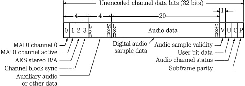
FIGURE 13.6 The AES10 (MADI) interface is used to connect multichannel digital audio equipment. The MADI channel format differs from the AES3 subframe format only in the first four bits.
The MADI channel format is based on the AES3 subframe format. A MADI channel differs from a subframe only in the first four bits, as shown in Fig. 13.6. Each channel therefore consists of 32 bits, with four mode identification bits, up to 24 audio bits, as well as the V, U, C, and P bits. The mode identification bits provide frame synchronization, identify channel active/inactive status, identify A and B subframes, and identify a block start. The 56 MADI channels are transmitted serially, starting with channel 0 and ending with channel 55, with all channels transmitted within one sampling period; the frame begins with bit 0 of channel 0. Because biphase coding is not used in the MADI format, preambles cannot be used to identify the start of each channel. Thus in MADI a 1 setting in bit 0 in channel 0 is used as a frame synchronization bit identifying channel 0, the first to be transmitted in a frame. Bit 0 is set to 0 in all other channels. Bit 1 indicates the active status of the channel. If the channel is active it is set to 1, and if inactive it is set to 0. Further, all inactive channels must have a higher channel number than the highest-numbered active channel. The bit is not dynamic, and remains fixed after power is applied. Bit 2 identifies whether a channel is A or B in a stereo signal; this also replaces the function of the preambles in AES3. Bit 3 is set when the user data and status data carried within a channel falls at the start of a 192-frame block. The remainder of the MADI channel is identical to an AES3 sub-frame. This is useful because MADI and AES3 are thus compatible, allowing free exchange of data.
MADI uses coaxial cables to support 100 Mbps. The interconnection is designed as a transmitter-to-receiver single-point to single-point link; for send and return links, two cables are required. Standard 75-Ω video coaxial cable with BNC connector terminations is specified; peak-to-peak transmitter output voltage should lie between 0.3 V and 0.6 V. Fiber-optic cable can also be used; for example, an FDDI interface could be used for distances of up to 2 kilometers. Alternatively, the Synchronous Optical NETwork (SONET) could be used. As noted, a distributed master synchronizing signal must be applied to all interconnected MADI transmitters and receivers. Because of the asynchronous operation, buffers are placed at both the transmitter and receiver, so that data can be reclocked from the buffers according to the master synchronization signal.
The audio data frequency can range from 32 kHz to 48 kHz, a ±12% variation is permitted. Higher sampling frequencies could be supported by transmitting at a lower rate, and using two consecutive MADI channels to achieve the desired sampling rate.
S/PDIF Consumer Interconnection
The S/PDIF (Sony/Philips Digital InterFace) interconnection protocol is designed for consumer applications. The IEC-60958 consumer protocol (known as type II) is a substantially identical standard. In some applications, the EIAJ CP-340 type II protocol is used. IEC-958 was named IEC-60958 in 1998. These consumer standards are very similar to the AES3 standard, and in some cases professional and consumer equipment can be directly connected. However, this is not recommended because important differences exist in the electrical specification, and in the channel status bits, so unpredictable results can occur when the protocols are mixed. Devices that are designed to read both AES3 and S/PDIF data must reinterpret channel status block information according to the professional (1) or consumer (0) status is the block’s first bit.
The overall structure of the consumer channel status block is shown in Fig. 13.7. It differs from the professional channel status block (see Fig. 13.4). The serial bits are arranged as twenty-four 8-bit bytes; only the first four bytes are defined.
Figure 13.8 provides specific details on bytes 0 through 23. They differ from the professional AES3 channel status block (see Fig. 13.5). Byte 0, bit 0 is set to 0, indicating consumer use; bit 1 specifies whether the data is audio (0) or nonaudio (1); bit 2 is the copyright or C bit, and indicates copy-protected (0) or unprotected (1); bit 3 shows use of pre-emphasis (if bit 1 shows audio data and bits 4 and 5 show two-channel audio); bits 6 and 7 set the mode, that defines bytes 1 through 3. Presently, only mode 00 is specified. Byte 1, bits 0 through 6, define a category code that identifies the type of equipment transmitting the data stream; byte 1, bit 7 (the 15th bit in the block) is the generation or L bit, and indicates whether data is original or copied. If a recorder with an S/PDIF input receives an AES3 signal, it can read the professional pre-emphasis indicator as a copy-prohibit instruction, and thus refuse to record the data stream. Likewise, a professional recorder can correctly identify a consumer data stream by examining bit 0 (set to 0), but misinterpret a consumer copy-inhibit bit as a sign that emphasis is not indicated. In mode 00, the category code in byte 1 defines a variety of transmitting formats including CD, DAT, synthesizer, sample rate converter, and broadcast reception. Byte 2 specifies source number and channel number, and byte 3 specifies sampling frequency and clock accuracy.
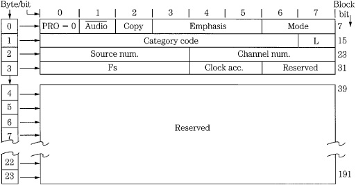
FIGURE 13.7 Specification of the 24-byte channel status block used in the consumer S/PDIF serial interface. (Sanchez, 1994)
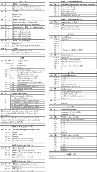
FIGURE 13.8 Description of the data contained in the 24-byte channel status block used in the S/PDIF serial interface. (Sanchez, 1994)
The category code, as noted, defines different types of digital equipment. This in turn defines the subframe structure, and how receiving equipment will interpret channel status information. For example, the category code for CD players (100) defines the sub-frame structure with 16 bits per sample, a sampling frequency of 44.1 kHz, control bits derived from the CD’s Q subcode, and places CD subcode data in the user bits. Subcode is transmitted as it is derived from the disc, one subcode channel bit at a time, over 98 CD frames. The P subcode, used to identify different data areas on a disc, is not transmitted. The start of subcode data is designated by a minimum of sixteen 0s, followed by a high start bit. Seven subcode bits (Q–W) follow. Up to eight 0s can follow for timing purposes, or the next start bit and subcode field can follow immediately. The process repeats 98 times until the subcode is transmitted. Subcode blocks from a CD have a data rate of 75 Hz. There is one user bit per audio sample, but there are fewer subcode bits than audio samples (12 × 98 = 1176) so the remaining bits are packed with 0s.
Unlike the professional standard, the consumer interface does not require a low-impedance balanced line. Instead, a single-ended 75-Ω coaxial cable is used, with 0.5 V peak-to-peak amplitude, over a maximum distance of 10 meters. To ensure adequate transmission bandwidth, video-type cables are recommended. Alternatively, some consumer equipment uses an optical Toslink connector and plastic fiber-optic cable over distances less than 15 meters. Glass fiber cables and appropriate code/decode circuits can be used for distances over 1 kilometer.
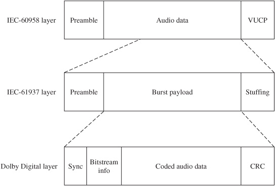
FIGURE 13.9 The protocol stack used by the IEC-61937 standard to convey multichannel data (such as Dolby Digital) via the IEC-60958 standard.
The IEC-61937 specification describes a multichannel interface. Low bit-rate data such as Dolby Digital, DTS, MPEG, or ATRAC can be substituted for the PCM data originally specified in the IEC-60958 protocol, as shown in Fig. 13.9. Because the data rate is reduced, a number of channels (such as 5.1 channels) can be conveyed in a nominally two-channel optical or coaxial interface. Receiving equipment reads channel-status information to determine the type of bitstream (IEC-60958 or IEC-61937). If the latter, the bitstream is directed to the appropriate decoder (such as Dolby Digital or DTS).
Serial Copy Management System
The Serial Copy Management System (SCMS) is used on many consumer recorders to limit the number of copies that can be derived from a recording. A user can make digital copies of a prerecorded, copyrighted work, but the copy itself cannot be copied; first-generation copying is permissible, but not second-generation copying. For example, a user can digitally copy from a CD to a second media, but a copy-inhibit flag is set in the second media’s subcode so that it is impossible to digitally copy from the second media. However, a SCMS-equipped recorder can record any number of digital copies from an original source. SCMS does not affect analog copying in any way. SCMS is a fair solution because it allows a user to make a digital copy of purchased software, for example, for compilation of favorite songs, but helps prevent a second party from copying music that was not paid for. On the other hand, SCMS might prohibit the recopying of original recordings, a legitimate use. Use of SCMS is mandated in the United States by the Audio Home Recording Act of 1992, as passed by Congress to protect copyrighted works.
The SCMS algorithm is found in consumer-grade recorders with S/PDIF (IEC-60958 type II) interfaces; it is not present in professional AES3 (IEC-60958 type I) interfaces. In particular, SCMS resides in the channel status bits as defined in IEC-60958 type II, Amendment No. 1 standard. This data is used to determine whether the data is copyrighted, and whether it is original or copied. The SCMS circuit first examines the channel status block (see Fig. 13.7) in the incoming digital data to determine whether it is a professional bitstream or a consumer bitstream. In particular, when byte 0, bit 0 is a 1, the bitstream is assumed to adhere to the AES3 standard; SCMS takes no action. SCMS signals do not appear on AES3 interfaces, and the AES3 standard does not recognize or carry SCMS information; thus, audio data is not copy-protected, and can be indefinitely copied. When bit 0 is set to 0, the SCMS identifies the data as consumer data. It examines byte 0, bit 2, the copyright or C bit; it is set to 0 when copyright is asserted, and set to 1 when copyright is not asserted. Byte 1, bit 7 (the 15th bit in the block) is the generation or L bit; it is used to indicate the generation status of the recording.
For most category codes, an L bit of 0 indicates that the transmitted signal is a copy (first-generation or higher) and a 1 means that the signal is original. However, the L bit may be interpreted differently by some product categories. For example, the meaning is reversed for laser optical products other than the CD: 0 indicates an original, and 1 indicates a copy. The L bit is thus interpreted by the category code contained in byte 1, bits 0 to 6 that indicate the type of transmitting device. In the case of the Compact Disc, because the L bit is not defined in the CD standard (IEC 908), the copy bit designates both the copyright and generation. Copyright is not asserted if the C bit is 1; the disc is copyrighted and original if the C bit is 0; if the C bit alternates between 0 and 1 at a 4-Hz to 10-Hz rate, the signal is first-generation or higher, and copyright has been asserted. Also, because the general category and A/D converter category without copyrighting cannot carry C or L information, these bits are ignored and the receiver sets C for copyright, and L to original.
Generally, the following recording scenario exists when bit 0 is set to 0, indicating a consumer bitstream: When bit C is 1, incoming audio data will be recorded no matter what is written in the category code or L bit, and the new copy can in turn be copied an unlimited number of times. When bit C is 0, the L bit is examined; if the incoming signal is a copy, no recording is permitted. If the incoming signal is original, it will be recorded, but the recording is marked as a copy by setting bits in the record-ing’s subcode; it cannot be copied. When no defined category code is present, one generation of copying is permitted. When there is a defined category code but no copyright information, two generations are permitted. However, different types of equipment respond differently to SCMS. For example, equipment that does not store, decode, or interpret the transmitted data, is considered transparent and ignores SCMS flags. Digital mixers, filters, and optical disc recorders require different interpretations of SCMS; the general algorithm used to interpret SCMS code is thus rather complicated.
By law, the SCMS circuit must be present in consumer recorders with the S/PDIF or IEC-60958 type II interconnection. However, some professional recorders, essentially upgraded consumer models, also contain an SCMS circuit. If recordists use the S/PDIF interface, copy-inhibit flags are sometimes inadvertently set, leading to problems when subsequent copying is needed.
High-Definition Multimedia Interface (HDMI) and DisplayPort
The High-Definition Multimedia Interface (HDMI) provides a secure digital connection for television and computer video, and multichannel audio. HDMI conveys full-bandwidth video and audio and is often used to connect consumer devices such as Blu-ray players and television displays. HDMI is compliant with HDCP (High-band-width Digital Content Protection). HDMI Version 1.0 was introduced in 2003, and has been improved in subsequent versions. For example, Version 1.0 permitted a throughput of 4.9 Gbps, and Version 1.3 permitted 10.2 Gbps. Version 1.4 adds an optional Ethernet channel and an optional audio return channel between connected devices. Version 1.4 also defines specifications for conveying 3D movie and game formats in 1080p/24 and 720p/60 resolution; Version 1.4a supports 3D broadcast formats.
The DisplayPort interface conveys video and audio data via a single cable connection and is an open-standard alternative to HDMI. DisplayPort is compatible with HDMI 1.3 and adapters can be used to interconnect them. DisplayPort 1.1 provides a throughput of 10.8 Gbps and also supports HDCP.
Musical Instrument Digital Interface (MIDI)
The Musical Instrument Digital Interface (MIDI) is widely used to interconnect electronic music instruments and other audio production equipment, as well as music notation devices. MIDI is not a digital audio interface because audio signals do not pass through it. Instead, MIDI conveys control information as well as timing and synchronization information to control musical events and system parameters of music devices. For example, striking a key on a MIDI keyboard generates a note-on message, containing information such as the note’s pitch and the velocity with which the key was struck. MIDI allows one instrument to control others, eliminating the requirement that each instrument have a dedicated controller. Since a MIDI file notates musical events, MIDI files are very small compared to WAV files and can be streamed with low overhead or downloaded very quickly. However, at the client end, the user must have a MIDI synthesizer installed on the local machine to render the data into music. Many sound cards contain MIDI input and output ports within a 15-pin joystick connector; an optional adapter is required to provide the 5-pin DIN jack comprising a MIDI port. A MIDI port provides 16 channels of communication, allowing many connection options.
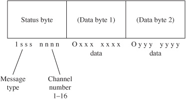
FIGURE 13.10 The general MIDI message protocol conveys data in sequences of up to three words, comprising one status word and two data words.
MIDI is an asynchronous, unidirectional serial interface. It operates at 31,250 bits/second (31.25 baud). The data format uses 8-bit bytes; most messages are conveyed as a one-, two-, or three-word sequence, as shown in Fig. 13.10. The first word in a sequence is a status word describing the type of message and channel number (up to 16). Status words begin with a 1 and may convey a message such as “note on” or “note off.” Subsequent words (if any) are data words. Data words begin with a 0 and contain message particulars. For example, if the message is “note on,” two data bytes describe which note and its playback level.
MIDI can also convey system exclusive messages with data relating to specific types of equipment. These sequences can contain any number of bytes. MIDI can also convey synchronization and timing information. Status bytes can convey MIDI beats, song pointers can convey specific locations from the start of a song, and MIDI Time Code (MTC) can convey SMPTE/EBU timecode. MIDI Show Control (MSC) is used to control multimedia and theatrical devices such as lights and effects. General MIDI (GM) standardizes many functions such as instrument definitions; it is used in many game and Internet applications where conformity is needed. MIDI connections typically use a 5-pin DIN connector, but XLR connectors can also be used. A twisted-pair cable is used over a maximum length of 50 feet. As shown in Fig. 13.11, many MIDI devices have three MIDI ports for MIDI In, MIDI Out, and MIDI Thru, to receive data, output data and to duplicate and pass along received data, respectively.
The original MIDI specification did not describe what instrument sounds (called patches) should be included on a synthesizer. Thus, a song recorded with piano, bass, and drum sounds on one synthesizer could be played back with different instruments on another. The General MIDI specification set a new standard for governing the ordering and naming of sounds in a synthesizer’s memory banks. This allows a song written on one manufacturer’s instrument to play back with the correct sounds on another manufacturer’s instrument. General MIDI provides 128 musical sounds and 47 percussive sounds.

FIGURE 13.11 The MIDI electrical interface uses In, Thru, and Out ports, typically using 5-pin DIN connectors.
AES11 Digital Audio Reference Signal
The AES11-1997 standard specifies criteria for synchronization of digital audio equipment in studio operations. It is important for interconnected devices to share a common timing signal so that individual samples are processed simultaneously. Timing inaccuracies can lead to increased noise, and even clicks and pops in the audio signal. With a proper reference, transmitters, receivers, and D/A converters can all work in unison. Devices must be synchronized in both frequency and phase, and be SMPTE time synchronous as well. It is relatively easy to achieve frequency synchronization between two sources; they must follow a common clock, and the signals’ bit periods must be equal. However, to achieve phase-synchronization, the bit edges in the different signals must begin simultaneously.
When connecting one digital audio device to another, the devices must operate at a common sampling frequency. Also, equally important, bits in the sending and received signals must begin simultaneously. These synchronization requirements are relatively easy to achieve. Most digital audio data streams are self-clocking; the receiving circuits read the incoming modulation code, and reference the signal to an internal clock to produce stable data. In some cases, an independent synchronization signal is transmitted. In either case, in simple applications, the receiver can lock to the bitstream’s sampling frequency.
However, when numerous devices are connected, it is difficult to obtain frequency and phase synchronization. Different types of devices use different timebases hence they exhibit noninteger relationships. For example, at 44.1 kHz, a digital audio bit-stream will clock 1471.47 samples per NTSC video frame; sample edges align only once every 10 frames. Other data, such as the 192-sample channel status block, creates additional synchronization challenges; in this case, the audio sample clock, channel status, and video frame will align only once every 20 minutes.
To achieve synchronization, a common clock with good frequency stability should be distributed through a studio. In addition, external synchronizers are needed to read SMPTE timecode, and provide time synchronization between devices. Figure 13.12 shows an example of synchronization for an audio/video studio. Timecode is used to provide general time lock; a master oscillator (using AES11 or video sync) provides a stable clock to ensure frequency lock of primary devices (the analog multitrack recorder is locked via an external synchronizer and synthesizers are not locked). It is important that the timecode reference is different from the frequency lock reference. In addition, most timecode sources are not sufficiently accurate to provide frequency and phase-locked references through a studio.
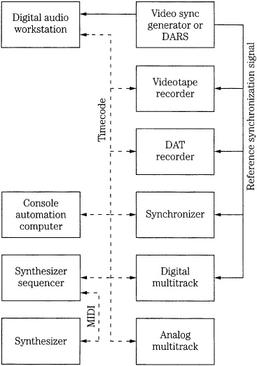
FIGURE 13.12 An example of synchronization in an audio/video studio showing a reference synchronization signal, timecode, and MIDI connections.
Although an AES3 line could be used to distribute a very stable clock reference, a dedicated word clock is preferred. Specifically, the AES11 Digital Audio Reference Signal (DARS) has been defined, providing a clocking signal with high frequency stability for jitter regulation. Using this reference signal, any sample can be time-aligned to any other sample, or with the addition of a timecode reference, aligned to a specific video frame edge. AES11 uses the same format and electrical configuration, and connectors as AES3; only the preamble is used as a reference clock. The AES11 signal is sometimes called “AES3 black” because when displayed it looks like an AES3 signal with no audio data present.
The AES11 standard defines Grade 1 long-term frequency accuracy (accurate to within ±1 ppm) and Grade 2 long-term accuracy (accurate to within ±10 ppm), where ppm is one part per million. Use of Grade 1 or 2 is identified in byte 4, bits 0 and 1 of the channel status block: Grade 1 (01), Grade 2 (10). With Grade 1, for example, a reference sampling clock of 44.1 kHz would require an accuracy of ±0.0441 Hz. A Grade 1 system would permit operation with 16- or 18-bit audio data; 20-bit resolution might require a more accurate reference clock, such as one derived from a video sync pulse generator (SPG). Time-code references lack sufficient stability. When synchronizing audio and video equipment, the DARS must be locked to the video synchronization reference. Frequency stability of the clocking in several audio and video interface signals is summarized in Table 13.1.
A separate word clock cable is run from the reference source to each piece of digital equipment through a star-type architecture, using a distribution amplifier as with a video sync pulse generator, to the reference clock inputs of all digital audio devices. Only a small buffer is needed to reclock data at the receiver. For example, a 5-ms buffer would accommodate 8 minutes of program that varies by ±10 ppm from the master reference. When A/D or D/A converters do not have internal clocks, and derive their clocks from the DARS, timing accuracy of the DARS must be increased; any timing errors are applied directly to the reconstructed audio signal. For 16-bit resolution at the converter, the AES11 standard recommends that peak sample clock modulation, sample to sample, be less than ±1 ns at all modulation frequencies above 40 Hz, and that random clock jitter, sample to sample, be less than ±0.1 ns per sample clock period, as shown in Fig. 13.13. Jitter is discussed in more detail in Chap. 4.
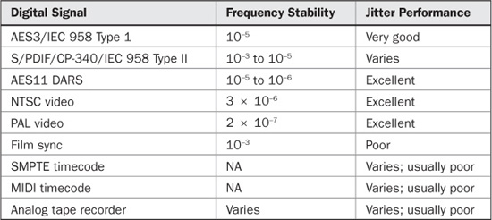
TABLE 13.1 Frequency stability of clocking in some audio and video interface signals.
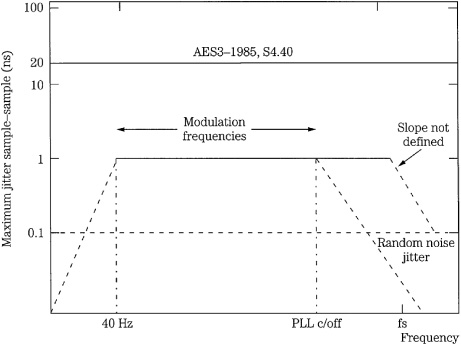
FIGURE 13.13 Timebase tolerances must be increased when DARS is used to clock sample converters. Recommended jitter limits for sample clocks in 16-bit A/D and D/A converters are depicted.
AES18 User Data Channels
The AES18-1996 standard describes a method for formatting the user data channels found within the AES3 interface. This format is derived from the packet-based High-Level Data Link Control (HDLC) communications protocol. It conveys text and other message data that might be related or unrelated to the audio data. The user data channel is a transparent carrier providing a constant data rate when the AES3 interface operates at an audio sampling frequency of 48 kHz ± 12.5%. A message is sent as one or more data packets, each with the address of its destination; a receiver reads only the messages addressed to it. Packets can be added or deleted as is appropriate as data is conveyed from one device to another. A packet comprises an address byte, control byte, address extension byte (optional), and an information field that is no more than 16 bytes. Multiple packets are placed in an HDLC frame; it contains a beginning flag field, packets, a CRCC field, and an ending flag. As described above, each AES3 subframe contains one user bit. User data is coded as an NRZ signal, LSB leading. Typical user bit applications can include messages such as scripts, subtitles, editing information, copyright, performer credits, switching instructions, and other annotations.
AES24 Control of Audio Devices
The AES24-1-1999 standard describes a method to control and monitor audio devices via digital data networks. It is a peer-to-peer protocol, so that any device may initiate or accept control and monitoring commands. The standard specifies the formats, rules, and meanings of commands, but does not define the physical manner in which commands (or audio signals) are transmitted; thus, it is applicable to a variety of communication networks. Using AES24, devices from different manufacturers can be controlled and monitored with a unified command set within a standard format. Each AES24 device is uniquely addressable by the transport network software, such as through a port number. Devices may be signal processors, system controllers, or other components, with or without user interfaces. Devices contain hierarchical objects that may include functions or controls such as gain controls, power switches, or pilot lamps. Object-to-object communication is provided because every object has a unique address. Object addresses have two forms: an object path (a pre-assigned text string) and an object address (a 48-bit unsigned integer).
Messages pass from one object to another; all messages share a common format and a set of exchange rules. In normal message exchange, an object creates and sends a message to another object, specifying a target method. Upon receiving the message, the required action is performed by the target method; if the original message requested a reply when the action has been completed, the target returns a reply stating the outcome. Because the standard is an abstraction, the action may be completed by any means, such as voltage-controlled amplifiers or digital signal processing software. AES24 subnetworks can be connected to form AES24 internetworks. Complex networks with bridges, hubs, and repeaters are possible. However, each device must be reachable by any other device. In one application, a PC-based controller may run a program with a graphical display of faders and meters (each one is an object). It communicates with external hardware processing devices (containing other objects) using the AES24 protocol. Other objects supervise initialization and configuration processes.
Sample Rate Converters
In a monolithic digital world, there would be one sampling frequency. In practice, the world is populated by many different sampling frequencies. Although 44.1 kHz and 48 kHz are the most common, 32 kHz is used in many broadcast applications. The AES5-1984 standard originally defined the use of these sampling frequencies. Sound cards use frequencies of 44.1, 22.05, and 11.025 kHz (among others), and 44.056 kHz is often used with video equipment. The DVD-Audio format defines several sampling frequencies including 88.2, 96, 176.4, and 192 kHz. The Blu-ray format can use 48-, 96-, and 192-kHz sampling frequencies. In addition, in many applications, vari-speed is used to bend pitch, producing radically diverse sampling rates.
Devices generally cannot be connected when their sampling rates differ. Even when sources are recorded at a common sampling frequency, their data streams can be asynchronous and thus differ by a few Hertz; they must be synchronized to an exact common frequency. In addition, a signal can be degraded by jitter. This changes the accuracy of the signal’s sample rate. In some cases, sample rate can be changed with little effort. For example, a 44.1-kHz signal can be converted to 44.056 kHz by removing a sample approximately every 23 ms, or about every 1000 samples. More typically, dedicated converters are needed.
A synchronous sample rate converter converts one rate to another using an integer ratio. The output rate is fixed in relation to the input rate; this limits applications. An asynchronous sample rate converter (ASRC) can accept a dynamically changing input sampling frequency, and output a constant and uninterrupted sampling frequency, at the same or different frequency. The input and output rates can have an irrational ratio relationship. In other words, the input and output rates are completely decoupled. In addition, the converter will follow any slow rate variations. This solves many interfacing problems.
Conceptually, sample rate conversion works like this: a digital signal is passed through a D/A converter, the analog signal is lowpass-filtered, and then passed through an A/D converter operating at a different sampling frequency. In practice, these functions can be performed digitally, through interpolation and decimation. The input sampling frequency is increased to a very high oversampling rate by inserting zeros in the bitstream, and then is digitally lowpass-filtered. This interpolated signal, with a very high data rate, is then decimated by deleting output samples and digitally lowpass-filtered to decrease output sampling frequency to a rate lower than the oversampling rate. The resolution of the conversion is determined by the number of samples available to the decimation filter. For example, for 16-bit accuracy, the difference between adjacent interpolated samples must be less than 1 LSB at the 16-bit level. This in turn determines the interpolation ratio; an oversampling ratio of 65,536 is required for 16-bit accuracy.
This ratio could be realized with a time-varying finite impulse response (FIR) filter of length 64, in which only nonzero data values are considered, but the required master clock signal of 3.27 GHz is impractical. Another approach uses polyphase filters. A low-pass filter highly oversampling by factor N can be decomposed into N different filters, each filter using a different subset of the original set of coefficients. If the subfilter coefficients are relatively fixed in time, their outputs can be summed to yield the original filter. They act as a parallel filter bank differing in their linear-phase group delays. This can be used for sample rate conversion. If input samples are applied to the polyphase filter bank, samples can be generated at any point between the input samples by selecting the output of a particular polyphase filter. An output sample late in the input sampling period would require a short filter delay (a large offset in the coefficient set), but an early output sample would demand a long delay (a short offset). That is, the offset of the coefficient set is proportional to the timing of the input/output sample selection. As before, accurate conversion requires 216 polyphase filters; in practice, reduction methods reduce the number of coefficients.
To summarize, by adjusting the interpolation and decimation processes, arbitrary rate changes can be accommodated. These functions are effectively performed through polyphase filtering. Input data is applied to a highly oversampled digital lowpass filter. It has a passband of 0 Hz to 20 kHz, and many times the filter coefficients needed to provide this response (equivalent to thousands of polyphase filters). Depending on the instantaneous temporal relationship between the input/output frequency ratio, a selected set of these coefficients processes input samples and compute the amplitude of output samples, at the proper output frequency.
The computation of the ratio between the input and output samples is itself digitally filtered. Effectively, when the frequency of the jitter is higher than the cutoff frequency of the polyphase selection process, the jitter is attenuated; this reduces the effect of any jitter on the input clock. Short periods of sample-rate conversion can thus be used to synchronize signals. An internal first-in first-out (FIFO) buffer is used to absorb data during dynamically changing input sample rates. Input audio samples enter the buffer at the input sampling rate, and are output at the output rate. For example, a timing error of one sample period can exist at the input, but the sampling rate converter can correct this by distributing the content of 99 to 101 input samples over 100 output samples. In this way, the ASRC isolates the jittered clock recovered from the incoming signal, and synchronizes the signal with an accurate low-jitter clock. Devices such as this make sample rate conversion essentially transparent to the user, and overcome many interfacing problems such as jitter. Because rate converters mathematically alter data values, when sampling rate conversion is not specifically required, it is better to use dedicated reclocking devices to solve jitter problems.
Fiber-Optic Cable Interconnection
With electric cable, information is transmitted by means of electrons. With fiber optics, photons are the carrier. Signals are conveyed by sending pulses of light through an optically clear fiber. Bandwidth is fiber optic’s forte; transmission rates of 1 Gbps are common. Either glass or plastic fiber can be used. Plastic fiber is limited to short distances (perhaps 150 feet) and is thicker in diameter than glass fiber; communications systems use glass fiber. The purity of a glass fiber is such that light can pass through 15 miles of it before the light’s intensity is halved. In comparison, 1 inch of window glass will halve light intensity. Fibers are pure to within 1 part per billion, yielding absorption losses less than 0.2 dB/km. Fiber-optic communication is not affected by electromagnetic and radio-frequency interference, lightning strikes and other high voltage, and other conditions hostile to electric signals. For example, fiber-optic cable can be run in the same conduit as high-power cables, or along the third rail of an electric railroad. Moreover, because a fiber-optic cable does not generate a flux signal, it causes no interference of its own. Because fiber-optic cables are nonmetallic insulators, ground loops are prevented. A fiber is safe because it cannot cause electrical shock or spark. Fiber-optics also provide low propagation delay, low bit-error rates, small size, light weight, and ruggedness.
Although bandwidth is very high, the physical dimensions of the fiber-optic cables are small. Fiber size is measured in micrometers, with a typical fiber diameter ranging from 10 μm to 200 μm. Moreover, many individual fibers might be housed in a thin cable. For example, there may be 6 independent fibers in a tube, with 144 tubes within one cable.
Any fiber-optic system, whether linking stereos, cities, or continents, consists of three parts: an optical source acting as an optical modulator to convert an electrical signal to a light pulse; a transmission medium to convey the light; and an optical receiver to detect and demodulate the signal. The source can be a light-emitting diode (LED), laser diode, or other component. Fiber optics provides the transmission channel. Positive-intrinsic-negative (PIN) photodiodes or avalanche photodiodes (APD) can serve as receivers. As with any data transmission line, other components such as encoding and decoding circuits are required. In general, low-bandwidth systems use LEDs and PINs with TTL interfaces and multimode fiber. High-bandwidth systems use lasers and APDs with emitter-coupled logic (ECL) interfaces and single-mode fiber.
Laser sources are used for long-distance applications. Laser sources can be communication laser diodes, distributed feedback lasers, or lasers similar to those used in optical disc pickups. Although the low-power delivery available from LEDs limits their applications, they are easy to fabricate and useful for short-distance, low-bandwidth transmission, when coupled with PIN photodiodes. Over longer distances, LEDs can be used with single-mode fiber and avalanche photodiodes. Similarly, selection of the type of detector often depends on the application. Data rate, detectivity, crosstalk, wavelength, and available optical power are all factors.
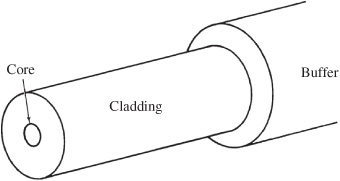
FIGURE 13.14 A fiber-optic cable is constructed with fiber core and cladding, surrounded by a buffer.
Fiber-Optic Cable
Optical fiber operates as a light pipe that traps entering light. The glass or plastic rod, called the core, is surrounded by a reflective covering, called the cladding, that reflects light back toward the center of the fiber, and hence to the destination. A protective buffer sleeve surrounds the cladding. A fiber-optic cable is shown in Fig. 13.14. The cladding comprises a glass or plastic material with an index of refraction lower than that of the core. This boundary creates a highly efficient reflector. When light traveling through the core reaches the cladding, the light is either partly or wholly reflected back into the core. If the angle of the ray with the boundary is less than the critical angle (determined from the refractive indexes of the core and the cladding), the ray is partly refracted into the cladding, and partly reflected into the core.
If the ray is incident on the boundary at an angle greater than the critical angle, the ray is totally reflected back into the core. This is known as total internal reflection (TIR). Thus, all rays at incident angles greater than the critical angle are guided by the core, affected only by absorption and connector losses. TIR is shown in Fig. 13.15 (see also Fig. 6.3). The principle of TIR is credited to British physicist John Tyndall. In 1870, using a candle and two beakers of water, he demonstrated that light could travel contained within a stream of flowing water.
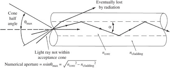
FIGURE 13.15 Total internal reflection (TIR) characterizes the propagation of light through the fiber. The numerical aperture of a stepped index optical fiber is a measure of its light acceptance angle and is determined by the refractive indexes of the core and the cladding.
In 1873, James Clerk Maxwell proved that the equations describing the behavior of electric waves apply equally to light. Moreover, he showed that light travels in modes—mathematically, eigenvalue solutions to his electromagnetic field equations that characterize wave guides. In the case of optical fiber, this represents one or more paths along the light wave guide. Multimode fiber-optic cable has a core diameter (perhaps 50 μm to 500 μm) that is large compared to the wavelength of the light source; this allows multiple propagation modes. The result is multiple path lengths for different modes of the optical signal; simply put, most rays of light are not parallel to the fiber axis.
Multimode fiber is specified according to the reflective properties of the boundary: stepped index and graded index. In stepped index fiber, the boundary between the core and cladding is sharply defined, causing light to reflect angularly. Light with an angle of incidence less than the critical angle will pass into the cladding. With graded index fiber, the index of refraction decreases gradually from the central axis outward. This gradual interface results in smoother reflection characteristics. In either case, in a multimode fiber, most light travels within the core.
Performance of multimode fiber is degraded by pulse-broadening caused by inter-modal and intramodal dispersion, both of which decrease the bandwidth of the fiber. Stepped index fiber is inferior to graded index in this respect. With intermodal dispersion (also called modal dispersion), some light reaches the end of a multimode fiber earlier than other light due to path length differences in the internal reflective angles. This results in multiple modes. In stepped index cable, there is delay between the lowest-order modes, those modes that travel parallel to the fiber axis, and the highest-order modes, those propagating at the critical angle. In other words, reflections at steeper angles follow a longer path length, and leave the cable after light traveling at shallow angles. A stepped index fiber can exhibit a delay of 60 ns/km. This modal dispersion significantly reduces the fiber’s available bandwidth per kilometer, and is a limiting factor. This dispersion is shown in Fig. 13.16A.
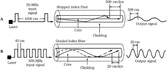
FIGURE 13.16 Fiber-optic cables are available as stepped index or graded index fibers. A. Stepped index fiber suffers from modal dispersion. B. Graded index fiber provides a higher transmission bandwidth.
Multimode graded index fiber has reduced intermodal dispersion. This is achieved by compensating for high-order mode delay to ensure that these modes travel through a lower refractive index material than the low-order modes, as shown in Fig. 13.16B. The high-order modes travel at a greater speed than the lower-order modes, compensating for their longer path lengths. Specifically, light travels faster near the cladding, away from the center axis where the index of refraction is higher. The velocity of higher mode light traveling farther from the core more nearly equals that of lower mode light in the optically dense center. Pulse-broadening is reduced, hence the data rate can be boosted. By selecting an optimal refractive index profile, this delay can be reduced to 0.5 ns/km.
Intramodal dispersion is caused by irregularities in the index of refraction of the core and cladding. These irregularities are wavelength-dependent, thus the delay varies according to the wavelength of the light source. Fibers are thus manufactured to operate at preferred light wavelengths.
In stepped and graded index multimode fibers, the degree of spreading is a function of cable length; bandwidth specification is proportional to distance. For example, a fiber can be specified at 500 kbps for 1 km. It could thus achieve a 500-kbps rate over 1 km or, for example, a 5-Mbps rate over 100 meters. In a multimode system, using either stepped or graded index fiber, wide core fibers carry several light waves simultaneously, often emitted from an LED source. However, dispersion and attenuation limit applications. Multimode systems are thus most useful in applications with short to medium distances and lower data rates.
Single-mode fiber was developed to eliminate modal dispersion. In single-mode systems, the diameter of the stepped index fiber core is small (perhaps 2 μm to 10 μm) and approaches the wavelength of the light source. Thus only one mode, the fundamental mode, exists through the fiber there is only one light path, so rays travel parallel to the fiber axis. For example, a wideband 9/125-μm single-mode fiber contains a 9-μm diameter light guide inside a 125-μm cladding. Because there is only one mode, modal dispersion is eliminated. In single-mode fibers, a significant portion of the light is carried in the cladding. Single-mode systems often use laser drivers; the narrow beam of light propagates with low dispersion and attenuation, providing higher data rates and longer transmission distances. For example, high-performance digital and radio frequency (RF) applications such as CATV (cable TV) would use single-mode fiber and laser sources.
The amount of optical power loss due to absorption and scattering is specified at a fixed wavelength over a length of cable, typically 1 km, and is expressed as decibels of optical power loss per km (dB/km). For example, a 50/125-μm multimode fiber has an attenuation of 2.5 dB/km at 1300 nm, and 4 dB/km at 850 nm. (Because light is measured as power, 3 dB represents a doubling or halving of power.) Generally, a premium glass cable can have an attenuation of 0.5 dB/km, and a plastic cable can exhibit 1000 dB/km.
Most fibers are best suited for operation in visible and near infrared wavelength regions. Fibers are optimized for operation in certain wavelength regions called windows where loss is minimized. Three commonly used wavelengths are approximately 850, 1300, and 1550 nm (353,000, 230,000, and 194,000 GHz, respectively). Generally, 1300 nm is used for long-distance communication; small fiber diameter (less than 10 μm) and a laser source must be used. Short distances, such as LANs (local-area networks), use 850 nm; LED sources can be used. The 1550-nm wavelength is often used with wavelength multiplexers so that a 1550-nm carrier can be piggybacked on a fiber operating at 850 nm or 1300 nm, running either in a reverse direction or as additional capacity.
Single-mode systems can operate in the 1310-nm and 1550-nm wavelength ranges. Multimode systems use fiber optimized in the 800-nm to 900-nm range. Generally, multi-mode plastic fibers operate optimally at 650 nm. In general, light with longer wavelengths passes through fiber with less attenuation. Most fibers exhibit medium losses (3 to 5 dB/km) in the 800-nm to 900-nm range, low loss (0.5 to 1.5 dB/km) at 1150-nm to 1350-nm region, and very low loss (less than 0.5 dB/km) at 1550 nm.
Fiber optics lends itself to time-division multiplexing, in which multiple independent signals can be transmitted simultaneously. One digital bitstream operating, for example, at 45 MHz, can be interleaved with others to achieve an overall rate of 1 GHz. This signal is transmitted along a fiber at an operating wavelength. With wavelength division multiplexing (WDM), multiple optical signals can be simultaneously conveyed on a fiber at different wavelengths. For example, transmission windows at 840, 1310, and 1550 nm could be used simultaneously. Independent laser sources are tuned to different wavelengths and multiplexed, and the optical signal consisting of the input wavelengths is transmitted over a single fiber. At the receiving end, the wavelengths are demultiplexed and directed to separate receivers or other fibers.
Connection and Installation
Fiber-optic interconnection provides a number of interesting challenges. Although the electrons in an electrical wire can pass through any secure mechanical splice, the light in a fiber-optic cable is more fickle through a transition. Fiber ends must be clean, planar, smooth, and touching—not an inconsiderable task considering that the fibers can be 10 μm in diameter. (In some cases, rounded fiber ends yield a more satisfactory transition.) Thus, the interfacing of fiber to connectors requires special consideration and tools. Fundamentally, fiber and connectors must be aligned and mechanically held together.
Fibers can be joined with a variety of mechanical splices. Generally, fiber ends are ground and polished and butted together using various devices. A V-groove strip holds fiber ends together, where they are secured with an adhesive and a metal clip. Ribbon splice and chip array splicers are used to join multifiber multimode fibers. A rotary splicer is used for single-mode fibers; fibers are placed in ferrules that allow the fibers to be independently positioned until they are aligned and held by adhesive. Many mechanical splices are considered temporary, and are later replaced by permanent fusion splicing; it is preferred because it reduces connector loss. With fusion splicing, fiber ends are heated to the fiber melting point, and fused together to form a continuous fiber. Specialized equipment is needed to perform the splice. Losses—as low as 0.01 dB—can be achieved.
Some fiber maintenance is simple; for example, to test continuity, a worker can shine a flashlight on one cable end, while another worker watches for light on the other end. Other measures are more sophisticated. An optical time-domain reflector (OTDR) is used to locate the position of poor connections or a break in a very long cable run. Light pulses are directed along a cable and the OTDR measures the delay and strength of the returning pulse. With short runs, a visual fault inspection can be best; a bright visible light source is used, and the cable and connectors are examined for light leaks. An optical power meter and a light source are used to measure cable attenuation and output levels. An inspection microscope is used to examine fiber ends for scratches and contamination. Although light disperses after leaving a fiber, workers should use eye protection near lasers and fiber ends. A fiber link does not require periodic maintenance. Perhaps the primary cause of failure is a “back hoe fade,” which occurs when a cable is accidentally cut during digging.
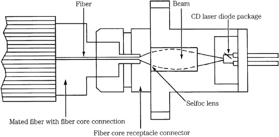
FIGURE 13.17 Laser-diode packages consolidate a laser diode, lens, and receptacle connector.
Various connectors and couplers are used in fiber installations. The purpose of an optical connector is to mechanically align one fiber with another, or with a transmitting or receiving port. Simple connectors allow fibers to be connected and disconnected. They properly align fiber ends; however, connector loss is typically between 0.5 dB and 2.0 dB, using butt-type connectors. Directional couplers connect three or more ports to combine or separate signals. Star couplers are used at central distribution points to distribute signals evenly to several outputs. Transmitters, such as the one shown in Fig. 13.17, and receivers integrate several elements into modules, simplifying installation. Subsystem integration provides data links in which the complete path from one buffer memory to another is integrated.
Design Example
Generally, the principal design criteria of a fiber-optic cable installation are not complex. Consider a system with a 300-foot fiber run from a microphone panel to a recording console. In addition, midway in the cable, a split runs to a house mixing console. Design begins by specifying the signal-to-noise (S/N) ratio of the fiber (as opposed to the S/N ratio of the audio signal) to determine the bit-error rate (BER). For example, to achieve a BER of 10−10 (1 error for every 1010 transmitted bits), an S/N of 22 dB would be needed. A multimode graded index fiber would be appropriate in terms of bandwidth and attenuation. For example, the manufacturer’s bandwidth length product (band factor) might be 400 MHz. For a fiber length of 300 feet (0.09 km), the cable’s optical bandwidth is the band factor divided by its length, yielding 4.4 GHz. Dividing this by 1.41 yields the cable’s electrical bandwidth of 3.1 GHz. The total system bandwidth is determined by:
1/BWtotal2 = 1/BWtrans2 + 1/BWrec 2 + 1/BWcable2
where the transmitter, receiver, and cable bandwidths are all considered. If BWtrans is 40 MHz, BWrec is 44 MHz, and BWcable is 3.1 GHz, total bandwidth BWtotal is 30 MHz.
If the cable’s attenuation is specified as 5.5 dB/km, this 0.09-km length would have 0.5 dB of attenuation. The splitter has a 3-dB loss. Total coupling loss at the connection points is 5.5 dB, and temperature and aging loss is another 6 dB. Total loss is 15 dB. The system’s efficiency can be determined: The adjusted output power is the difference between the transmitter output power and the detector sensitivity. For example, selected parts might yield figures of −8 dB and −26 dB, respectively, yielding an adjusted output power of 18 dB. The received signal level would yield an acceptable S/N ratio of 56 dB. The power margin is the difference between the adjusted power output and the total loss. In this case, 18 dB − 15 dB = 3 dB, a sufficient power margin, indicating a good choice of cable, transmit and receive parts with respect to system loss.
As with any technology involving data protocol, standards are required. In the case of fiber optics, Fiber Distributed Data Interface (FDDI) and FDDI II are two standards governing fiber-optic data communications networks. They interconnect processors and can form the basis for a high-speed network, for example, linking workstations and a file server. FDDI uses LED drivers transmitting at a nominal wavelength of 1310 nm over a multimode fiber with a 62.5-μm core and 125-μm cladding, with a numerical aperture of 0.275. Connections are made with a dual-fiber cable (separate send and receive) using a polarized duplex connector. FDDI offers data bandwidths of 100 MHz with up to 500 station connections. The FDDI II standard adds greater flexibility to fiber-optic networking. For example, it allows a time-division multiplexed mode providing individual routes with a variety of data rates.
The Synchronous Optical NETwork (SONET) provides wideband optical transmission for commercial users. The lowest bandwidth optical SONET protocol is OC-1 with a bandwidth of 51.84 Mbps. A 45-Mbps T-3 signal can be converted to an STS-1 (synchronous transport signal level 1) signal for transmission over an OC-1 cable. Other protocols include OC-3 (155.52 Mbps) for uncompressed NTSC digital video, and OC-12 (622.08 Mbps) for high-resolution television. SONET is defined in the ANSI T1.105-1991 standard. Telecommunications is discussed in more detail in Chap. 15.