
Microcontrollers
The microcontroller is essentially a computer on a chip. It contains a processing unit, ROM, RAM, serial communications ports, ADCs, and so on. In essence, a microcontroller is a computer, but without the monitor, keyboard, and mouse. These devices are called microcontrollers because they are small (micro) and because they control machines, gadgets, and so on.
With one of these devices, you can build an “intelligent” machine. You write a program on a host computer; download the program into the microcontroller via the USB, parallel, or serial port of the PC; and then disconnect the programming cable and let the program run the machine. For example, in the microwave oven, a single microcontroller has all the essential ingredients to read from a keypad, write information to the display, control the heating element, and store data such as cooking time.
There are literally thousands of different kinds of microcontrollers available. Some are one-time-programmable (OTP), meaning that once a program is written into its ROM (OTP-ROM), no changes can be made to the program. OTP microcontrollers are used in devices such as microwaves, dishwashers, automobile sensor systems, and many application-specific devices that do not require changing the core program. Other microcontrollers are reprogrammable, meaning that the microcontroller’s program stored in ROM (which may be EPROM, EEPROM, or flash) can be changed if desired, which is a useful feature when prototyping or designing test instruments that may require future I/O devices.
Microcontrollers are found in bicycle light flashers, data loggers, toys such as model airplanes and cars, antilock braking systems, VCRs, microwave ovens, alarm systems, fuel injectors, exercise equipment, and many other items. They also can be used to construct robots, where the microcontroller acts as the robot’s brain, controlling and monitoring various input and output devices, such as light sensors, stepper and servo motors, temperature sensors, and speakers. With a bit of programming, you can make the robot avoid objects, sweep the floor, and generate various sounds to indicate that it has encountered difficulties (such as being low on power or tipped over) or has finished sweeping. The list of applications for microcontrollers is endless, and because they are so widely used, their cost is low.
Figure 13.1 shows the basic ingredients found within many microcontrollers. These include a CPU, ROM (OTP-ROM, EPROM, EEPROM, of flash), RAM, I/O ports, timing circuitry/leads, interrupt control, a serial port adapter (such as UART or USART), and an ADC/DAC.
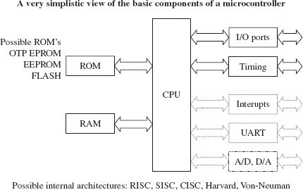
FIGURE 13.1
The CPU retrieves program instructions that the user programs into ROM, while using RAM to store temporary data needed during program execution. The I/O ports are used to connect external devices that send or receive instructions to or from the CPU.
The serial port adapter is used to provide serial communications between the microcontroller and a PC or between two microcontrollers. It is responsible for controlling the different rates of data flow common between devices. Example serial port adapters found within microcontrollers are the universal asynchronous receiver transmitter (UART) and universal synchronous/asynchronous receiver transmitter (USART). The UART can handle asynchronous serial communications, while the USART can handle either asynchronous or synchronous serial communications. Some microcontrollers take this a step further and include an interface for a Universal Serial Bus (USB) interface on the chip.
An interrupt system is used to interrupt a running program in order to process a special routine called the interrupt service routine. This boils down to the ability of a microcontroller to respond to external data that requires immediate attention, such as data conveyed by an external sensor indicating important shutdown information, say, when things get too hot or objects get too close. A timer/counter is used to “clock” the device—to provide the driving force needed to move bits around. Most microcontrollers that come with built-in ADCs and DACs can be used to interface with analog transducers, such as temperature sensors, strain gauges, and position sensors.
13.2 Example Microcontrollers
There are many different families of microcontrollers. Two of the most popular are made by the manufacturers Atmel and Microchip. In this section, we will take a close look at microcontrollers from these two manufacturers.
The Atmel ATtiny85 microcontroller is an 8-pin IC available in both surface-mount and through-hole DIL packages. The device is designed to operate with a minimum of external components. Figure 13.2 shows what is inside one of these little packages.
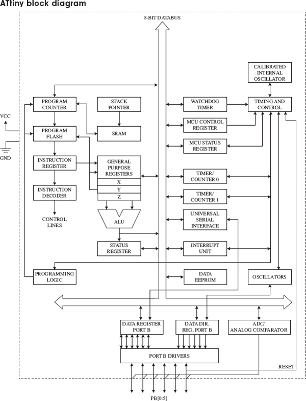
FIGURE 13.2
The ATtiny 85 has three different types of memory:
• 8 kB of flash memory in which the program instructions are stored
• 256 bytes of SRAM, which is used to contain data during execution of instructions
• 512 bytes of EEPROM that is used to store nonvolatile data that needs to be retained after a loss of power
The watchdog timer allows the microcontroller to be put into a sleep mode, in which it consumes negligible power. The watchdog timer will wake up the microcontroller after a certain amount of time has passed.
The device can either use the inaccurate internal oscillator or two of the pins that would otherwise be used for inputs or outputs can be sacrificed to use an external crystal oscillator.
Two timers can be used to generate internal interrupts; that is, to trigger some code to be executed periodically. External interrupts that are triggered by a change in the level at a pin are also possible.
All of the I/O pins can also be used with the internal ADC.
The ATtiny also has a Universal Serial Interface, which can communicate with a number of different types of serial buses including USB, Inter-Integrated Circuit (I2C), and serial. There is more about these serial protocols in Section 13.5.
Minimizing External Components
Figure 13.3 illustrates just how few components you need to make something with an ATtiny. The potentiometer is connected to a pin that will be used as an analog input, which could, for example, be used to control the rate at which the LED flashes.
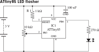
FIGURE 13.3
The resistor R1 could be replaced by a direct connection from the RESET pin to VCC, but by using a resistor here, it becomes possible to have the RESET pin low force a reset—something that is necessary during programming.
The chip will operate from a supply voltage of between 2.7 V and 5.5 V at a clock frequency of 10 MHz or below, making it suitable for running from a 3 V lithium cell or a pair of AA batteries. The clock frequency can be set during programming, and it can also be changed from program code while the ATtiny is actually running. The main reason for controlling the clock frequency is to reduce the power consumption. At 1 MHz, the power can be reduced to just 300 μA and in power-down mode, waiting for an interrupt from the watchdog timer, power consumption is just 0.1 μA.
You may be wondering why we used a microcontroller to create something that we could have made with a 555 timer. Well, why not? The microcontroller is more expensive than a 555 timer, but only around a dollar, and also we can use slightly fewer components with a microcontroller. We also have a great deal more flexibility. Using this same hardware, we could do clever tricks such as turning the LED completely off if the potentiometer is at its most counterclockwise position. And there are three other unused I/O pins that we could do something with.
The catch is that to use a microcontroller, you need to program. But, if you are serious about developing something that will eventually become a product, chances are it will have a microcontroller in it.
Programming the ATtiny with AVR Studio
Atmel, the makers of the ATtiny, supply an integrated development environment (IDE) called AVR Studio (see Fig. 13.4) that takes away some of the pain of microprocessor programming.
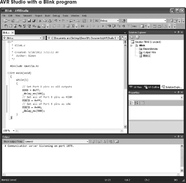
FIGURE 13.4
The ATtiny is usually programmed in C, which offers a good compromise between performance and readability. We define readability as the property of a program that allows it to be understood by someone other than the person who wrote it.
The standard AVR Studio way of doing things is powerful and flexible, but the C that you need to write is at a fairly low level, and not nearly as accessible as the BASIC Stamp language.
Programming the ATtiny with Arduino
Many people use the Arduino library to simplify the writing of code. This library includes all sorts of utility functions, rather like the commands found in the BASIC Stamp language. The Arduino library was developed from a project called Wiring, which is a useful library for AVR microcontrollers. It is used mostly with the Arduino development boards (see Section 13.4). However, the Arduino IDE (different from AVR Studio) can also be used to write the programs for most processors in the AVR 8-bit range, including the ATtiny85.
Figure 13.5 shows the program that would control the hardware of Fig. 13.4 within the Arduino IDE.
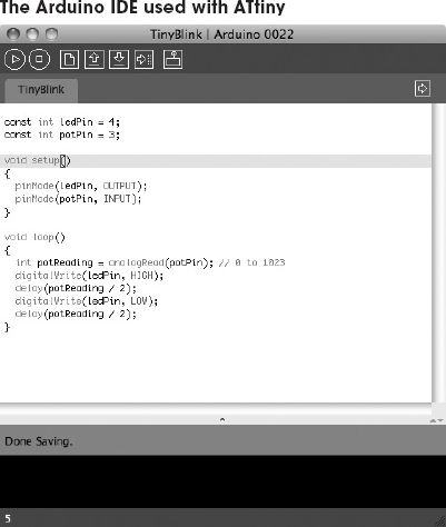
FIGURE 13.5
The Arduino IDE is open source and runs on Mac, Linux, and Windows systems. You need to install some extra configuration and library files to make the Arduino IDE work with the ATtiny microcontrollers. These instructions were developed at MIT. and details for installing and downloading can be found at http://hlt.media.mit.edu/?p=1695.
The advantages of using an ATtiny microcontroller here rather than a full Arduino board are reduced cost (an ATtiny costs $1 or less) and lower power consumption. We will meet the Arduino in Section 13.4.
Whether you are programming the microcontroller with AVR Studio or Arduino, you will need USB programmer hardware that is connected to a USB port of your computer. The programmers use a technique called in-circuit system programming (ICSP), which uses a six pin header connected to pins on the ATtiny. This is one of the reasons that you use a resistor to tie up the RESET pin, as it is one of the pins used by the programmer. It is quite common to design this header into the PCB for the circuit, during development, allowing changes to be easily made to the firmware.
If you find that you need more I/O pins, or you can make do with less memory and save cost, you may want to consider one of the other microcontrollers in the ATtiny range. The Atmel website contains comparison tables for all its microcontrollers at http://www.atmel.com/products/microcontrollers/avr/tinyAVR.aspx?tab=parameters.
13.2.2 The PIC16Cx Microcontrollers
Having briefly explored the ATtiny85 microcontroller, we turn our attention to some rival devices from Microchip. Like the ATtiny range, these microcontrollers are 8-bit.
Figure 13.6 shows Microchip’s PIC16Cx range of microcontrollers. As you can see in the internal architecture diagram, both microcontrollers house on-chip CPU, EPROM, RAM, and I/O circuitry. The architecture is based on a register file concept that uses separate buses and memories for programs and data (Harvard architecture). This allows execution to occur in parallel. As an instruction is being “pre-fetched,” the current instruction is executing on the data bus.
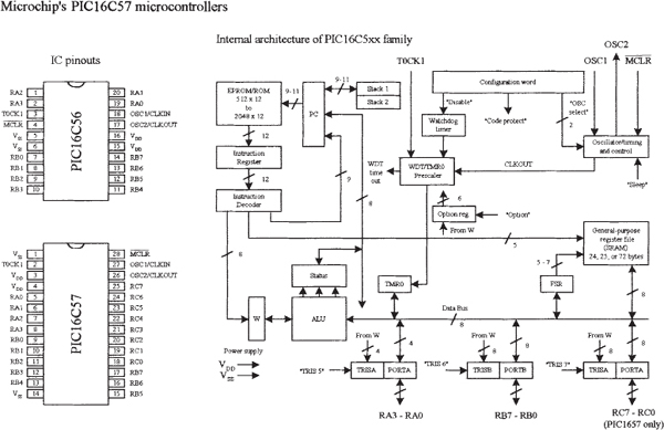
FIGURE 13.6
The PIC16C56’s program memory (EPROM) has space for 1024 words, while the PIC16C57 has space for 2048 words. An 8-bit-wide ALU contains one temporary working register, and performs arithmetic and Boolean functions between data held in the working register and any file register. The ALU and register file are composed of up to 80 addressable 8-bit registers, and the I/O ports are connected via the 8-bit-wide data bus. Thirty-two bytes of RAM are directly addressable, while the access to the remaining bytes work through bank switching.
In order for bit movement to occur (clock generation), the PIC controllers require a crystal or ceramic resonator connected to pins OSC1 and OSC2. The PIC microcontrollers reach a performance of 5 million instructions per second (5 MIPS) at a clock frequency of 20 MHz. A watchdog timer is also included, which is a free-running on-chip RC oscillator that works without external components. It continues running when the clock has stopped, making it possible to generate a reset independent of whether the controller is working or sleeping.
These chips also come with a number of I/O pins that can be linked to external devices such as light sensors, speakers, LEDs, or other logic circuits. The PIC16C56 comes with 12 I/O pins that are divided into three ports: port A (RA3–RA0), port B (RB7–RB0), and port C (RC7–RC0). The PIC16C57 comes with eight more I/O pins than the PIC16C56.
Programming the PIC Microcontroller
Microcontrollers use a set of machine-code instructions (1’s and 0’s) to perform various tasks such as adding, comparing, sampling, and outputting data via I/O ports. These machine-code instructions are typically programmed into onboard ROM (EPROM, EEPROM, or flash) via a programming unit linked to a PC. The actual programming, however, isn’t written out in machine code. It is written in a high-level language within an editor program running on the PC. The high-level language used may be a popular language such as C or a specially tailored language that the manufacturer has created to optimize all the features present within its microcontrollers. For ultimate performance, the user can revert to assembly language, which could also reduce memory usage and program size but at the expense of readability of the code.
Using a manual and software you get from the manufacturer, you learn to write statements that tell the microcontroller what to do. You type the statements in an editor program, and then use the compile/run option to check for syntax errors. Once you think the program is ready, you save it and run a compiler program to translate it into machine language. If there is an error in your program, the compiler may refuse to perform the conversion. In this case, you must return to the text editor and fix the bugs before moving on.
Once the bugs are eliminated and the program is compiled successfully, a third piece of software is used to load the program into the microcontroller. This may require physically removing the microcontroller from the circuit and placing it into a special programmer unit linked to the host PC or may use ICSP, as described in the previous section.
Another way to do things involves using an interpreter instead of a compiler. An interpreter is a high-level language translator that resides within the microcontroller’s ROM, rather than in the host PC. This often means that an external ROM (EPROM, EEPROM, or flash) is needed to store the actual program. The interpreter receives the high-level language code from the PC and, on the spot, interprets the code and places the translated code (machine code) into the external ROM, where it can be used by the microcontroller.
The interpreter approach may seem like a waste of memory, since the interpreter consumes valuable on-chip memory space. Also, using an interpreter significantly slows things down—a result of needing to retrieve program instructions from external memory. However, using an interpreter provides a very important advantage. By having the interpreter onboard to translate on the spot, an immediate, interactive relationship between the host program and microcontroller is created. This allows you to build your program, immediately try out small pieces of code, test the code by downloading the chunks into the microcontroller, and then see if the specific chunks of code work. The host programs used to create the source code often come with debugging features that let you test to see where possible programming or hardwiring errors may result by displaying the results (such as the logic state at a given I/O pin) on the computer screen while the program is executing within the microcontroller. This allows you to perfect specific tasks within the program, such as a sound-generation routine, a stepper motor control routine, and so forth.
A halfway house between using interpreted code (BASIC Stamp, which we’ll look at next) and compiled machine code (AVR Studio) is to use a microcontroller with a boot loader installed into its EEPROM (Arduino). In this approach, a small boot loader program is installed once into the flash memory of the microcontroller. The boot loader then runs after every reset of the microcontroller and quickly checks for incoming programming commands on the serial port. If it finds them, it reads the serial data into the flash memory of the device so that it can then be run. This removes the need for special programming hardware.
Programming the PIC with BASIC Stamp
The BASIC Stamp is essentially a microcontroller with interpreter software built in. These devices also come with additional support circuitry, such as an EEPROM, voltage regulator, ceramic oscillator, and so on. BASIC Stamps are ideal for beginners because they are easy to program, quite powerful, and relatively cheap—a whole startup package costs around $80 or so. These devices are also very popular among inventors and hobbyists, and you’ll find a lot of helpful literature, application notes, and fully tested projects on the Internet.
The original Stamp was introduced in 1993 by Parallax, Inc. It got its name from the fact that it resembled a postage stamp. The early version of the BASIC Stamp was the REV D. Later improvements led to the BASIC Stamp I (BSI) and then BASIC Stamp II (BSII).
Both the BSI and BSII have a specially tailored BASIC interpreter firmware built into the microcontroller’s EPROM. For both Stamps, a PIC microcontroller is used. The actual program that is to be run is stored in an onboard EEPROM. When the battery is connected, the Stamps run the BASIC program in memory. Stamps can be reprogrammed at any time by temporarily connecting them to a PC running a simple host program. The new program is typed in, a key is hit, and the program is loaded into the Stamp. I/O pins can be connected with other digital devices such as sense switches, LED displays, LCDs, servos, and stepper motors.
Here, we’ll focus on the BSII. To get started with the BSII, you will need programming software, programming cable, the manual, the BASIC Stamp module, and an appropriate carrier board (optional). These all come in the BSII startup kit, at a lower cost than purchasing each part separately.
For more information about the BASIC Stamp family, visit http://www.parallax.com/tabid/436/Default.aspx.
Note: To fully understand all the finer details needed to program BASIC Stamps, it is necessary to read through the user’s manual. However, reading the user’s manual alone tends not to be the best learning strategy, as it is easy to lose your place within all the technical terms, especially if you are a beginner. A good source to learn more about BASIC Stamps is the book Programming and Customizing the Basic Stamp Computer by Scott Edwards (McGraw-Hill, 2001). This book is geared toward beginners and is easy reading.
BASIC STAMP II
BSII is a module that comes in a 24-pin DIL package (see Fig. 13.7). The brain of the BSII is the PIC16C57 microcontroller that is permanently programmed with a PBASIC2 instruction set within its internal one-time programmable EPROM (OTP-EPROM). When programming the BSII, you tell the PIC16C57 to store symbols, called tokens, in external EEPROM memory. When the program runs, the PIC16C57 retrieves tokens from memory, interprets them as PBASIC2 instructions, and carries out those instructions. The PIC16C57 can execute its internal program at a rate of 5 MIPS. However, each PBASIC2 instruction takes up many machine instructions, so the PBASIC2 executes more slowly, around 3 to 4 MIPS.
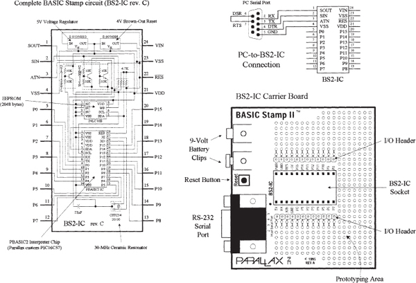
FIGURE 13.7
The BSII comes with 16 I/O pins (P0–P15) that are available for general use by your programs. These pins can be interfaced with all modern 5-V logic, from TTL through CMOS (technically, they have characteristics like the 74HCT logic series). The direction of a pin—either input or output—is set during the programming phase. When a pin is set as an output pin, the BSII can send signals to other devices, like LEDs and servos. When a pin is set as an input pin, it can receive signals from external devices, such as switches and photosensors. Each I/O pin can source 20 mA and sink 25 mA. Pins P0–P7 and pins P8–P15, as groups, can each source a total of 40 and sink 50 mA per group.
2048-BYTE EEPROM
The BSII’s PIC’s internal OTP-EPROM is permanently programmed at the factory with Parallax’s firmware, which turns this memory into a PBASIC2 interpreter chip. Because they are interpreters, the Stamp PICs have the entire PBASIC language permanently programmed into their internal program memory. This memory cannot be used to store your PBASIC2 program. Instead, the main program must be stored in the EEPROM, which retains data without power and can be reprogrammed easily. At runtime, the PBASIC2 program created on the host computer is loaded into the BSII’s EEPROM starting at the highest address (2047) and working downward. Most programs do not use the entire EEPROM, which means that PBASIC2 lets you store data in the unused lower portion of the EEPROM. Since programs are stored from the top of the memory downward, data is stored in the bottom of the memory working upward. If there is an overlap, the Stamp host software will detect this problem and display an error message.
RESET CIRCUIT
The BSII comes with a reset circuit. When power is first connected to the Stamp, or if it falters due to a weak battery, the power supply voltage can fall below the required 5 V. During such brownouts, the PIC is in a voltage-deprived state and will have the tendency to behave erratically. For this reason, a reset chip is incorporated into the design, forcing the PIC to reset to the beginning of the program and hold until the supply voltage is within acceptable limits.
POWER SUPPLY
To avoid supplying the BSII with unregulated supply power, a 5-V regulator is incorporated into the BSII. This regulator accepts a voltage range from slightly over 5 V up to 15 V and regulates it to a steady 5 V. It provides up to 50 mA. The regulated 5 V is available at output VDD, where it can be used to power other parts of your circuits, as long as no more than 50 mA is required.
CONNECTING BSII TO A HOST PC
To program a Stamp requires connecting it to a PC that runs host software to allow you to write, edit, download, and debug PBASIC2 programs. The PC communicates with the BSII through an RS-232 (COM port) interface consisting of pins SIN, SOUT, and ATM (serial in, serial out, and attention, respectively).
During programming, the BSII host program pulses ATM high to reset the PIC and then transmits a signal to the PIC through
SIN indicating that it wants to download a new program. PC-to-BSII connector hookup is shown in Fig. 13.7. This connection allows the PC to reset the BSII for programming, download programs, and receive debug data from the BSII. The additional pair of connections, pin 6 and 7 of the DB9 socket, lets the BSII host software identify the port to which the BSII is connected.Usually, when programming a BSII, you use a special BSII carrier board, which comes with a prototyping area, I/O header, BSII-IC socket, 9-V battery clips, and an RS-232 serial port connector, as shown in Fig. 13.7. These boards, along with programming cable and software, can be purchased as startup packages.
THE PBASIC LANGUAGE
Even though the BASIC Stamp has BASIC in its name, it cannot be programmed in Visual BASIC. It does not have a graphical user interface, a hard drive, or a lot of RAM. The BASIC Stamp must be programmed only with Parallel’s BASIC, PBASIC, which has been specifically designed to exploit all the BASIC Stamp’s capabilities.
PBASIC is a hybrid form of the BASIC programming language, with which many people are familiar. PBASIC is called a hybrid because, while it contains some simplified forms of normal BASIC control constructs, it also has special commands to efficiently control I/O pins. PBASIC is an easy language to master and includes familiar instructions such as GOTO, FOR … NEXT, and IF … THEN. It also contains Stamp-specific instructions, such as PULSOUT, DEBUG, and BUTTON, which will be discussed shortly.
The actual program to be downloaded into the Stamp is first written using BSII editor software running on a Microsoft Windows PC, or on a Linux or Mac system running Windows using virtualization software. After you write the code for your application, you simply connect the Stamp to a serial port or USB-to-serial adapter connected to your computer, provide power to the Stamp, and download the code into the Stamp. As soon as the program has been downloaded successfully, it begins executing its new program from the first line of code.
The size of the program that can be stored in a Stamp is limited. For the BSII, 2048 bytes worth of program space are available, which is enough for around 500 to 600 lines of PBASIC code. The amount of program memory for the Stamps cannot be expanded, since the interpreter chip (PIC) expects the memory to be specific and fixed in size. However, in terms of data memory, expansion is possible. You can interface EEPROM or other memory devices to the Stamp’s I/O pins to gain more data storage area. This requires that you supply the appropriate code within your PBASIC program to make communication between the Stamp and external memory device you choose possible. Additional data memory is often available with Stamp-powered applications that monitor and record data (such as from an environmental field instrument).
The PBASIC language, like other high-level computer languages, involves defining variables and constants and using address labels, mathematical and binary operators, and various instructions (including branching, looping, numerics, digital I/O, serial I/O, analog I/O, sound I/O, EEPROM access, time, power control, and so on). Here’s a quick rundown of the elements of the PBASIC2 language.
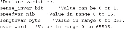
Comments: Comments can be added within the program to describe what you’re doing. They begin with an apostrophe (’) and continue to the end of the line.
Variables: These are locations in memory that your program can use to store and recall values. These variables have limited range. Before a variable can be used in a PBASIC2 program, it must be declared. The common way used to declare variables is to use a directive VAR:
where the symbol can be any name that starts with a letter; can contain a mixture of letters, numbers, and underscore; and must not be the same as PBASIC keywords or labels used in the program. The size establishes the number of bits of storage the variable is to contain. PBASIC2 provides four sizes: bit (1 bit), nib (4 bits), byte (8 bits), and word (16 bits). Here are some examples of variable declarations:
Constants: Constants are unchanging values that are assigned at the beginning of the program and may be used in place of the numbers they represent within the program. Defining constants can be accomplished by using the CON directive:
By default, PBASIC2 assumes that numbers are in decimal (base 10). However, it is possible to use binary and hexadecimal numbers by defining them with prefixes. For example, when the prefix % is placed in front of a binary number (for example, %0111 0111), the number is treated as a binary number, not a decimal number. To define a hexadecimal number, the prefix $ is used (as in $EF). Also, PBASIC2 will automatically convert quoted text into the corresponding ASCII codes. For example, defining a constant as A will be interpreted as the ASCII code for A (65).
Address labels: The editor uses address labels to refer to addresses (locations) within the program. This is different from other versions of BASIC, which use line numbers. In general, an address label name can be any combination of letters, numbers, and underscores. However, the first character in the label name cannot be a number, and the label name must not be the same as a reserved word, such as a PBASIC instruction or variable. The program can be told to go to the address label and follow whatever instructions are listed after. Address labels are indicated with a terminating colon (for example, loop:).
Mathematical operators: PBASIC2 uses two types of operators: unary and binary. Unary operators take precedence over binary operators. Also, unary operations are always performed first. For example, in the expression 10 – SQR 16, the BSII first takes the square root of 16 and then subtracts it from 10. The unary operators are as follows:
ABS |
Returns absolute value |
SQR |
Returns square root of value |
DCD |
2n-power decoder |
NCD |
Priority encoder of a 16-bit value |
SIN |
Returns 2’s complement sine |
COS |
Returns 2’s complement cosine |
The binary operators are as follows:
+ |
Addition |
− |
Subtraction |
Division |
|
// |
Remainder of division |
* |
Multiplication |
** |
High 16 bits of multiplication |
*/ |
Multiplies by 8-bit whole and 8-bit part |
MIN |
Limits a value to specified low |
MAX |
Limits a value to specified high |
DIG |
Returns specified digit of number |
<< |
Shifts bits left by specified amount |
>> |
Shifts bits right by specified amount |
REV |
Reverses specified number of bits |
& |
Bitwise AND of two values |
| |
Bitwise OR of two values |
^ |
Bitwise XOR of two values |
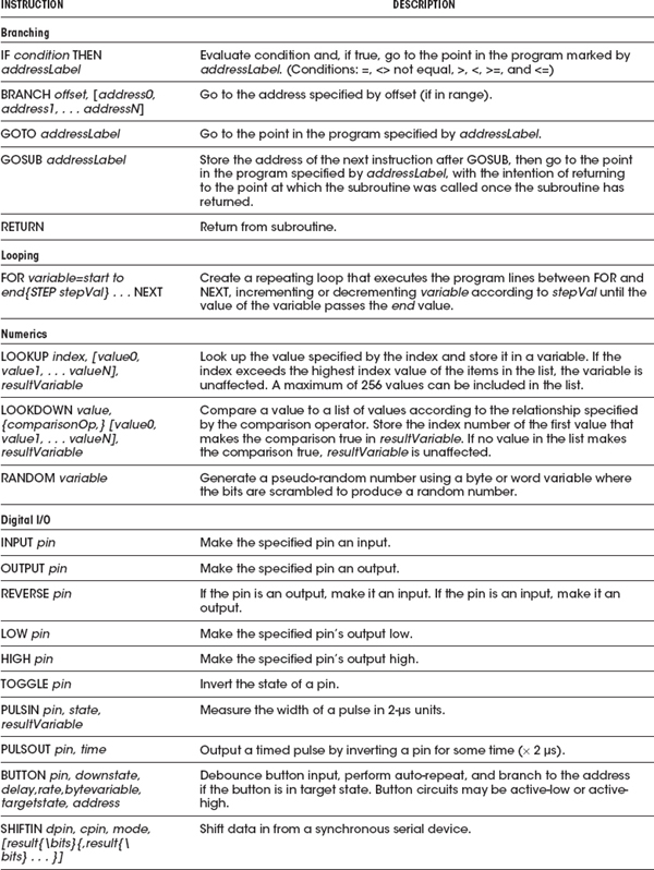
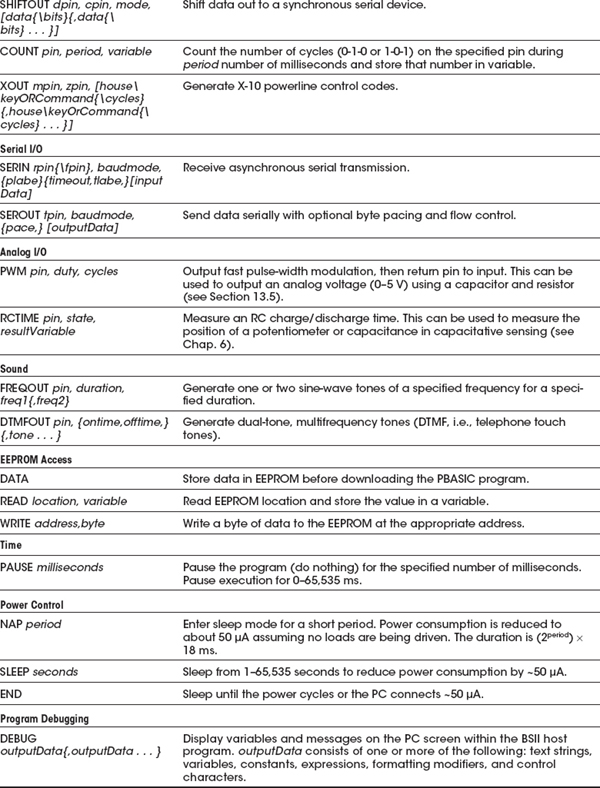
Table 13.1 shows the PBASIC instructions used by BSII.
DEBUGGING
To debug PBASIC programs, the BASIC Stamp editor comes with two handy features: syntax checking and a DEBUG command.
Syntax checking alerts you to any syntactical error and is automatically performed on your code the moment you try to download to the BASIC Stamp. Any syntax errors will cause the download process to abort and will cause the editor to display an error message, pointing out the error in the source code.
The DEBUG command, unlike syntax checking, is an instruction that is written into the program to find logical errors—ones that the Stamp does not find, but ones that the designer had not intended. DEBUG operates similar to the PRINT command in the BASIC language and can be used to print the current status of specific variables within your PBASIC program as it is executed within the BASIC Stamp. If your PBASIC code includes a DEBUG command, the editor opens a special window at the end of the download process to display the result for you.
Making a Robot Using BSII
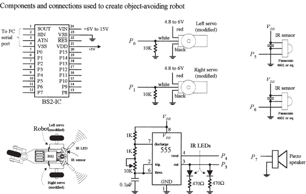
To demonstrate how easy it is to make interesting gadgets using BSII, let’s take a look at a robot application. In this application, the main objective is to prevent the robot from running into objects. The robot aimlessly moves around, and when it comes close to an object, the robot stops and then backs up and moves off in another direction. In this example, the robot is constructed as follows:
• A BSII acts as the robot’s brain.
• Two servos connected to wheels act as its legs.
• A pair of infrared transmitters and sensors acts as its eyes.
• A piezoelectric speaker acts as it voice.
Figure 13.8 shows the completed robot, along with the various individual components.
THE SERVOS
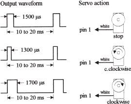
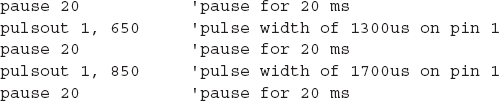
The directional movement of the robot is controlled by right and left servo motors that have been modified so as to provide a full 360 degrees worth of rotation (modifying a servo is discussed in Chap. 14). To control a servo requires generating pulses ranging from 1000 to 2000 μs in width at intervals of approximately 20 ms. With one of the servos used in our example, when the pulse width sent to the servo’s control line is set to 1500 μs, the servo is centered—it doesn’t move. However, if the pulse width is shortened to, say, 1300 μs, the modified servo rotates clockwise. Conversely, if the pulse width is lengthened to, say, 1700 μs, the modified servo rotates counterclockwise.
The actual control pulses used to drive one of the servos in the robot are generated by the BSII using the PULSOUT pin, time1 and the PAUSE time2 instructions. The pin represents the specific BSII pin that is linked to a servo’s control line, and time1 represents how long the pin will be pulsed high. Note that for the PULSOUT instruction, the decimal placed in the time1 slot actually represents half the time, in microseconds (s), that the pin is pulsed high. For example, PULSOUT 1, 1000 means that the BSII will pulse pin 1 high for 2000 μs, or 2ms. For the PAUSE instruction, the decimal placed in the time2 slot represents a pause in milliseconds. For example, PAUSE 20, represents a 20-ms pause. Figure 13.9 shows sample BSII code used to generate desired output waveforms to control a servo.
The pulse widths need to be repeated for them to have a practical effect on the motors. It may be worth expanding this fragment to show loops of a second or more for each of the pulse widths.
Note that this sequence of pulses must be repeated every 20 ms or so for the servo to maintain its position.
IR TRANSMITTERS AND RECEIVERS
The robot’s object-detection system consists of a right and left set of infrared (IR) LED transmitters and IR detector modules. The IR LEDs are flashed via a 555 timer at a high frequency, which in this example happens to be 38 kHz, 50 percent duty cycle. This frequency is used to avoid interference from other household sources of IR light, primarily incandescent lights, and to match the IR sensor shown in the figure. (Many types of IR LED transmitters and sensors could be used in this robot, and they may work best using a different frequency.) It is also possible to generate these pulses using the BASIC Stamp, but we have chosen to use external hardware to keep the program simple.
The IR photons emitted by the LED rebound off objects in the path of the robot and reflect back to the IR detector module. When a detector module receives photons, the I/O pin of the BSII connected to the module goes low. Note that the BSII can execute only around 4000 instructions per second, while the number of pulses generated by the detector module is 38,000. In this case, the actual number of pulses received by the BSII will be less—around 10 or 20.
PIEZOELECTRIC SPEAKER
A piezoelectric speaker is linked to one of the BSII I/O terminals and is used to generate different sounds when the robot is moving forward or backing up. To provide the piezoelectric speaker with a sinusoidal waveform to generate sound, the FREQOUT pin, time, frequency instruction is used. The instruction FREQOUT 7, 1000, 440 creates a 440-Hz sinusoidal frequency on pin 7 that lasts for 1000 ms.
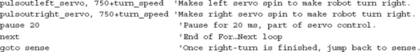
THE PROGRAM
The following is a program used to control the robot. It is first created using the PBASIC2 host software, and then downloaded into the BSII during runtime.
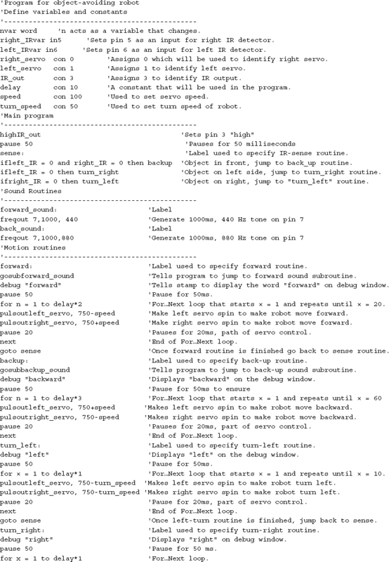
Note: Due to production tolerances, the motors may not stop rotating when pulsing at 1500 μs, so a small “fudge factor” may need to be added to or subtracted from the PULSOUT values.
Thinking about Mass Production
Recall that the major components of the BASIC Stamp circuit are the PIC (houses the CPU and ROM for storing PBASIC interpreter), external EEPROM (stores the program), and the resonator. In large-scale runs, it would be nice to get rid of the external memory and remove the interpreter program, and simply download a compiled PBASIC code directly into the PIC. This would save space and money. As it turns out, the BASIC Stamp editor software includes a feature to program PBASIC code directly into a PIC microcontroller using Parallax’s PIC16Cxx programmer.
The major benefit of starting out with the Stamp is that you can easily fine-tune your code, test chunks, and immediately see if it works, which is important when creating prototypes. When prototyping with a PIC, checking for errors is much harder because you must compile everything at once—you can’t test out chunks of code.
13.2.3 32-Bit Microcontrollers
The microcontrollers that we have explored in the previous sections use an 8-bit data bus with a clock frequency in the tens of megahertz and a few kilobytes of storage. Anyone familiar with the microprocessor-based home computers of the 1980s and 1990s would recognize the specifications. In comparison to a modern smartphone with a 32-bit processor, clock frequencies in the gigahertz, and hundreds of megabytes of RAM, these microcontrollers offer lamentable performance. However, the important thing here is what they are being used for. The adage of “not using a sledgehammer to crack a nut” was never more appropriate.
Atmel, Microchip, and most of the other microcontroller manufacturers all produce high-performance microcontrollers that use a 32-bit data bus and have more memory and processing performance than most desktop computers had ten years ago. These are useful for some high-performance applications. If you find that you need this kind of performance, then it is worth considering using one from a manufacturer whose 8-bit devices you are already familiar with, as they generally use the same or similar software tools and can be programmed in much the same way. They just cost a lot more and work a lot faster.
13.2.4 Digital Signal Processing
If you have a microcontroller that has an ADC input and a DAC output, you can digitize an audio signal (let’s say music), process the data in some way, and then send it back out through the DAC. You might create a graphics equalizer or a dynamic voice changer that raises the pitch of your voice by an octave. This is called digital signal processing (DSP).
While you can do simple low-quality DSP with a standard 8-bit microcontroller, the ADCs are often too slow and the algorithms such as Fourier transforms that you apply to the audio signal must work in real time, and therefore benefit greatly from a fast CPU.
Microchip (among others) has variants of its standard microcontroller lines specifically designed for DSP. The dsPIC from Microchip is one such device that is frequently used in low-cost DSP applications. It has a 16-bit internal data bus, a 40 MHz clock, and 2kB of RAM.
Note: DSP is a complex area, and there are many good books devoted to this topic. Understanding Digital Signal Processing by Richard G. Lyons (Pearson, 1996) is one such book.
13.3 Evaluation/Development Boards
The microcontroller manufacturers are very keen to get their products into your products, so most will offer low-cost development and evaluation boards for their microcontrollers. These will often take the form of a PCB that contains the microcontroller, supporting components such as a crystal oscillator and voltage regulator, and a prototyping area where you can add your own components. They can also usually be programmed from a USB or sometimes RS-232 serial port, for which you will need to find an ancient PC, or more likely, use a USB-to-serial convertor. These boards include the use of the manufacturers’ preferred software development tools, although these are sometime limited in some way unless you buy the professional version of the software.
As well as boards produced by the microcontroller manufacturers, other boards are offered by third parties. These boards can be useful during the development process, as they make prototyping much easier than starting from scratch.
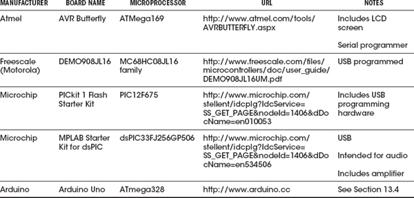
Table 13.2 lists some of the most popular development boards available at the time of writing.
TABLE 13.2 Popular Microcontroller Evaluation Boards
Arduino is an open source hardware platform for microcontroller prototyping. It encompasses both a microcontroller development board and an IDE. The IDE is simple to use and available for Mac, Linux, and Windows computers.
Arduino boards are extremely popular as a starting point for using microcontroller technologies. Their popularity is due to a number of factors, including the following:
• Low cost (around $30)
• Open source design
• Easy-to-use and cross-platform IDE
• Availability of plug-in shields (expansion hardware)
13.4.1 A Tour of Arduino
The most popular Arduino board is the Arduino Uno (see Fig. 13.10). This board is based on an Atmel microcontroller, similar to the ATtiny called ATmega328 (although the ATtiny can also be programmed using the Arduino IDE).
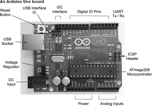
FIGURE 13.10
The ATmega328 microcontroller has 32kB of flash memory for storing programs, 2kB of RAM, and 1kB of EEPROM. It also has a hardware serial interface, or UART, as well as the usual timers and interrupt capabilities.
The microcontroller itself is the large 28-pin IC in the bottom right of the board, as shown in Fig. 13.10. Beneath this are six analog pins that can also be used as digital I/O pins, and then a block of power connections.
The Arduino can either be powered through the DC input socket (7–12 V dc) or from USB, and will switch over automatically to whichever is supplied.
The connectors on the top side of the board offer an I2C interface, which actually uses two of the analog pins (A4 and A5) in the Arduino Uno, but they are repeated here for future boards that may have a separate I2C interface. There is also a row or digital I/O pins, some marked as being pulse-width modulation (PWM) capable. Two of these, D0 and D1, double as the Rx and Tx pins on the UART.
13.4.2 The Arduino IDE
The Arduino IDE provides a simple-to-use editor into which you can type your programs and upload them onto your Arduino board over USB (see Fig. 13.11). As well as the program editing area, the Arduino IDE also provides the following features:
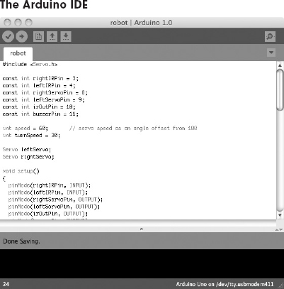
FIGURE 13.11
• Color syntax highlighting
• A status area where the memory usage of your completed program is shown
• Links to the Arduino library documentation
• A serial monitor that allows two-way communication with the Arduino’s USB port
Most of the Arduino boards, including the Arduino Uno, have a USB connector through which they can be programmed. So, after writing your program, or “sketch” as it is called in Arduino parlance, you select the type of board and click the Upload button. Your program will be compiled and loaded into the flash memory of the microcontroller.
13.4.3 Arduino Board Models
Along with the Arduino Uno, there are many other Arduino boards to suit different uses. They are all programmed in the same way, but have different sizes, costs, and numbers of I/O pins available.
New Arduino models are released quite often. As an open source project, different manufacturers frequently take a basic model and add some different features to it.
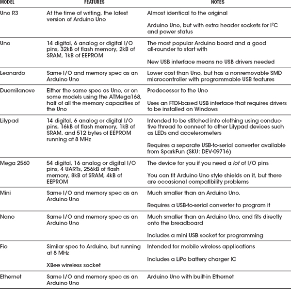
Some of the most used official Arduino models are listed in Table 13.3.
TABLE 13.3 Kinds of Arduino Boards
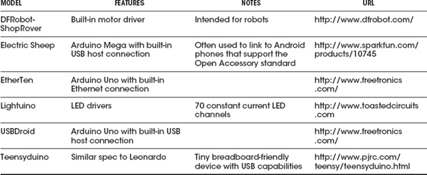
Along with the boards listed in Table 13.3, other manufacturers offer boards that simply replicate the features of the official designs with minor differences. More interesting are the special-purpose Arduino boards. Some of these are listed in Table 13.4.
13.4.4 Shields
The success of Arduino had been in no small part due to the wide range of plug-in shields that add useful features to a basic Arduino board. A shield is designed to fit into the header sockets of the main Arduino board (see Fig. 13.12). Most shields will then pass through these connections in another row of header sockets, making it possible to construct stacks of shields with an Arduino at the bottom. Shields that have a display on them will not normally pass through in this way. You also need to be aware that if you stack shields in this way, you need to make sure that there are no incompatibilities, such as two of the shields using the same pin. Some shields get around this problem by providing jumpers to add some flexibility to pin assignments.
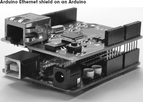
FIGURE 13.12
There are shields available for almost anything you could want an Arduino to do. They range from relay control to LED displays and audio file players. Most of these are designed with the Arduino Uno in mind, but are also usually compatible with the Arduino Mega.
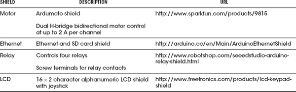
An encyclopedic list that includes useful technical details about the pin usage of these shields can be found at http://shieldlist.org/. Some of the author’s favorite shields are listed in Table 13.5.
13.4.5 The Arduino C Library
You may hear people refer to the “Arduino language,” but Arduino is actually just programmed in the C programming language, which has been around for many years. But Arduino provides a set of Arduino core functions that you can use in your programs, or sketches.
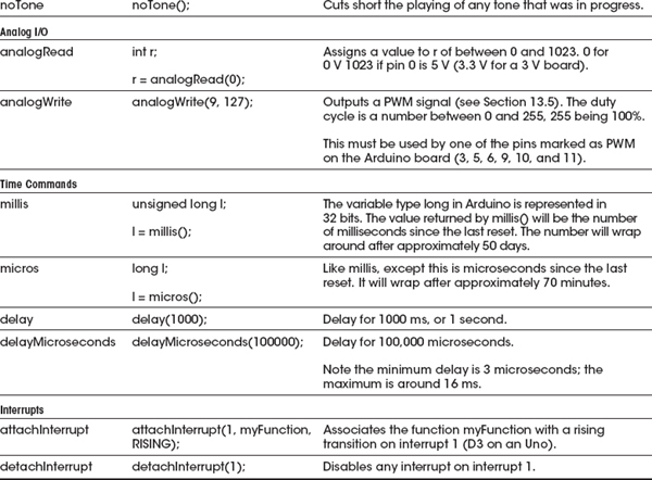
There are a large number of commands available in the Arduino library. A selection of the most commonly used commands are listed in Table 13.6.
TABLE 13.6 Arduino Library Functions
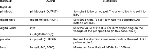
The main Arduino core, including all the commands listed in Table 13.6, is automatically included in every sketch that you write. However, there are a number of other libraries that come bundled with the Arduino IDE that are added to your code only when you use them. To include them, use the include command followed by the name of the library, like this:
This command includes the Servo library that we will use in the example Arduino project that follows.
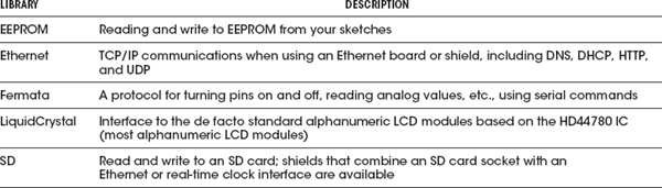
The libraries that are included in the Arduino IDE are listed in Table 13.7.
TABLE 13.7 Standard Arduino Libraries
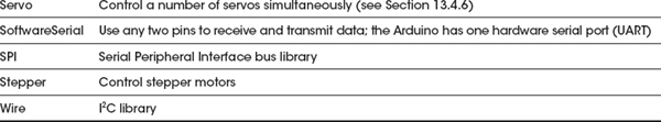
As well as the official Arduino libraries, as an open system, anyone can write a library and contribute it to the community, and many of these are extremely useful. Some of these other libraries are listed in Table 13.8.
For more information about Arduino, the official Arduino website (http://www.arduino.cc) should be your first port of call.
13.4.6 Arduino Example Project
We are going to repeat the BASIC Stamp example project, using the same external electronics, but controlled by an Arduino rather than a BSII. The following listing shows the code needed to control the robot.
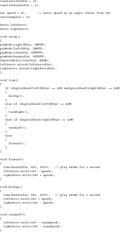
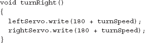
There are many obvious similarities with the BASIC Stamp version. However, the C language used by Arduino provides a little more structure to the program, and seasoned programmers will probably feel happier using C rather than BASIC.
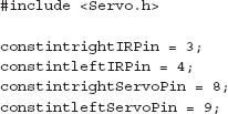
As noted in the previous section, a feature of the Arduino platform is the large number of libraries, both official and user-supplied, that can be included in the program. The first line includes a library for controlling servos. Strictly speaking, this is C++, the object-oriented extension to C. So, to control a servo, we first need to create an instance (well, two in this case):
Then we need to associate it with a particular pin using the following:
From now on, all we need to do is give the servo an angle in degrees, using the write command, like this:
There is no need to worry about pulse lengths; all this is handled for us automatically.
13.4.7 Taking the Arduino Offboard
For all its convenience and ease of use, an Arduino Uno is just a microcontroller with the necessary support components to provide it with a regulated voltage and allow it to be programmed over USB. When the time comes to create a product, if it is a one-off, you will probably just use the Arduino as it is, and buy yourself a replacement for the next project. If however, you will be producing a number of devices, you will probably want to lose the Arduino board and just use the programmed microcontroller in your project.
Taking the Arduino offboard means that you will probably design your own PCB for the microcontroller that includes just those features of the Uno that you need in your project, along with those extra components that may have been provided by a shield or connections to other electronics on, say, a breadboard.
The ATmega328 is not as easy to run using an internal oscillator as the ATtiny.
The IDE expects an external clock (crystal or ceramic resonator). You will probably also want to use a voltage regulator IC to provide a stable voltage to the microcontroller.
The schematic shown in Fig. 13.13 was produced in Eagle CAD, along with the corresponding board shown in Fig. 13.14.
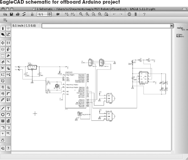

FIGURE 13.14
Whether you are using an ATtiny, a PIC, or an Arduino, you can be fairly certain that you will need to connect some components to it. At the very least, there will probably be a switch or two.
You can use three types of interfaces to your microcontroller:
• Digital: Switches as inputs, LEDs or similar as outputs
• Analog: Sensors of various types (see Chap. 6)
• Serial: A serial communications protocol of which there are four main types: TTL serial, I2C, 1-Wire, and Serial Peripheral Interface (SPI).
In the following sections, we will assume that your microcontroller has both analog and digital inputs, as well as digital and PWM outputs. It is also assumed that the microcontroller is operating at 5V. This may not always be the case, as many microcontrollers can be used at lower voltages, and 3.3 V is another common choice. If this is the case, you will need to adapt some of the schematics.
13.5.1 Switches
Single Switches
Switches are easy to connect to a digital input (see Fig. 13.15). Note the use of pullup resistors that keep the pin high until it is closed. When the switch is of the normally closed variety, then that current will be drawn continually, so you may want to use a high value of resistor there—say, 10 kΩ. However, for a normally open switch, current will flow only when the switch is pressed, so 1 kΩ is fine.
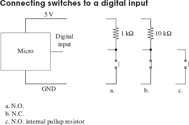
FIGURE 13.15
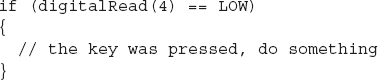
With the switch to GND, as shown in all the examples in Fig. 13.15, when the switch is closed, the digital input will go low. This means that the logic of a button being pressed is inverted, as shown in the following sample Arduino C code.
It is also possible to swap over the switch and resistor, so that the resistor is now a pulldown resistor, and the switch being closed will result in a logical HIGH at the input.
The choice of pullup resistor depends on how electrically noisy your environment is and how long the leads are from the microcontroller to the switch. Essentially, it is a compromise between immunity to noise and current consumption. Given that for a normally open switch, current will flow only when the button is pressed, 5 mA using a 1 kΩ resistor is not normally a problem. In fact, some would advocate a lower value, such as 270 Ω.
Many microcontrollers include internal pullup resistors that can be turned on and off for a particular digital input. On an ATmega and ATtiny microcontroller, this resistor typically has a value of 20 k to 40 kΩ, so in a noisy environment or if the lead to the switch is long, an external pullup resistor may be better.
Multiple Switches to One Analog Input
If you have a lot of switches and do not want to tie up a load of digital inputs, then a common technique is to use an analog input and a number of resistors. The voltage at the analog input will then depend on the switches that are pressed (see Fig. 13.16).
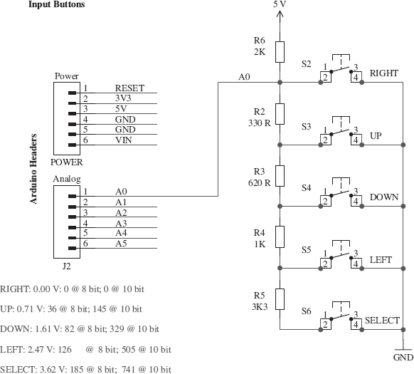
FIGURE 13.16
Figure 13.16 is taken from the schematic diagram for the Freetronics Arduino LCD shield, where it is used for the five switches of a joystick type arrangement of push buttons (thanks to Freetronics for permission to use this diagram). Note how the decimal values for 10-bit A to D for each button are given as a table.
Multiple switches and an analog input
The analog reading will not normally be exactly the value required due to resistor tolerances and power supply voltage changes, so in the code that interprets this, you would normally specify a band that would indicate a certain button, rather than just one value.
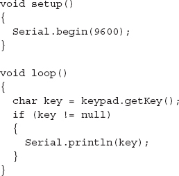
Using a Matrix Keypad
Keypads use switches arranged in a matrix, as shown in Fig. 13.17. The 4 × 3 keypad shown in the figure has a key at the intersection of each row and column. To determine which keys are pressed, the microcontroller will take each of the output pins Q0 to Q2 high in turn, and see what value is presented at each of the inputs I0 to I3. Note that if the microprocessor does not support internal pullup resistors, then these pullup resistors would be required on each input.
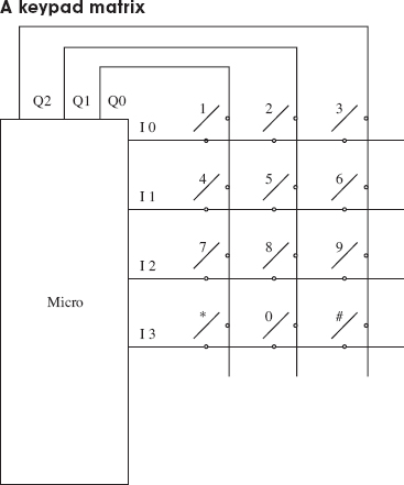
FIGURE 13.17
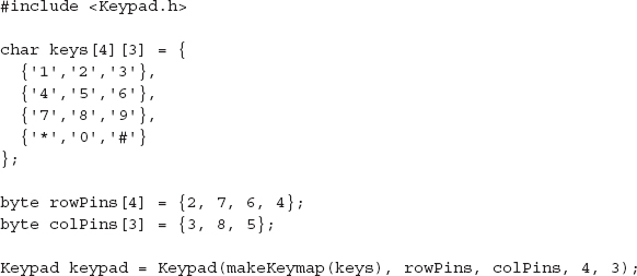
In practice, this is such a common component for microcontrollers that to write your own code for it would be needlessly reinventing the wheel. As an example, the following is the Arduino code for this that uses a library.
Debouncing
Attach an oscilloscope to the output of any of the circuits in Fig. 13.15, and you are likely to see an output something like what is shown in Fig. 13.18 when the switch is closed. This is called bouncing.
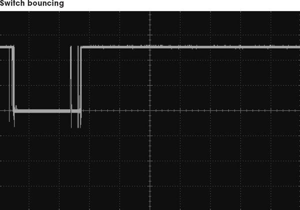
FIGURE 13.18
Switch bouncing can cause problems. Imagine the situation where pressing a button toggles an LED on and off. If there are an even number of bounces, then the LED will toggle on and then immediately off again, giving the impression that nothing happened.
It is therefore a good idea to debounce any switches that are connected to a microcontroller input. Although it is perfectly possible to do this with hardware—say, with a monostable that ignores subsequent pulses from the switch after triggering—it reduces the component count if you do the debouncing in software.
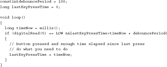
As with keyboard matrices, debouncing is a common problem that has been solved many times. The essence of software debouncing is the same as hardware debouncing, and that is to take action on the first transition and then ignore any subsequent transitions of the output until a safe debounce period has elapsed. Depending on what else the microcontroller has to do, this can be as simple as inserting a delay for the debounce period in the code that immediately follows the detection of the first transition. However, sometimes this is not possible, such as when the microcontroller has other responsibilities (like refreshing an LED display). In these cases, a common approach is to set a variable to the milliseconds tick after the first transition and make a condition of actioning the button press that sufficient debounce time has elapsed. The Arduino code for this is as follows.
13.5.2 Analog Inputs
Many of the sensors described in Chap. 6 provide an analog output to indicate the property that they are reading. For example, the TMP36 temperature sensor IC would typically be connected directly to an analog input of a microcontroller, as shown in Fig. 13.19.
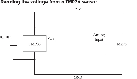
FIGURE 13.19
If you are measuring a voltage that is outside the range of the microcontroller’s analog input (say 0 to 10 V), then you can just use two resistors as a voltage divider to reduce the voltage appropriately. If there is a risk that the voltage may exceed the expected range, you can protect the microcontroller’s analog input by adding a zener diode (see Fig. 13.20).
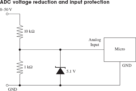
In practice, the zener diode will start to conduct before 5.1 V, to the detriment of the linearity of the readings, which is why the input range is labeled as 0 to 50 V, rather than 0 to 55 V. Remember the voltage divider is 1:11, not 1:10.
If switching behavior is required, then this should be implemented in code rather than through hardware. This approach allows more flexibility, for instance, for adding hysteresis or changing the set temperature. The following Arduino C code illustrates a simple temperature-control algorithm with 4 (±2) degrees of hysteresis.
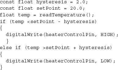
This example assumes that there is a user-supplied function called read Temperature.
For measuring resistance, sensors that are resistive, like LDRs and thermistors, will usually simply be used as one leg of a potential divider to produce a voltage that can be read. This is discussed in the relevant sensor sections in Chap. 6.
13.5.3 High-Power Digital Outputs
Most microcontrollers will reliably provide us with only around 20 mA of source or sink current as a direct digital output. If you want to drive a higher power load, such as a relay or a high-power LED, then you need to use a transistor.
Note that Arduino will handle up to 40 mA per pin with a maximum per chip of 200 mA. These figures should be derated by 25 percent for a production product, but Atmel says that the chip can comfortably cope with the absolute maximum current ratings, as these figures are already derated.
Figure 13.21 shows how to accomplish this with bipolar transistors, and Fig. 13.22 shows how to use MOSFETs.
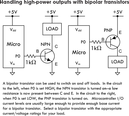
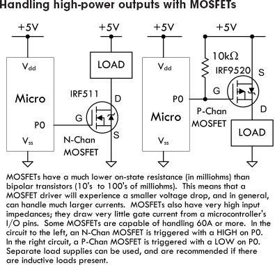
FIGURE 13.22
MOSFETs have a number of advantages over bipolar transistors. One is that for most applications, they do not need a gate resistor. However, MOSFETs are a capacitative load, so the inrush current when the pin changes state can be very high, albeit for a very short duration. Microcontrollers will generally cope with this, but for ultimate adherence to design rules, use a gate resistor of around 1 kΩ.
Another advantage of using MOSFETs as switches is their exceptionally low drain-source on resistance and high off resistance. This makes a small MOSFET capable of controlling quite big loads. However, you should check the gate threshold voltage to make sure that it is not above the logic level. For instance, an N-channel MOSFET with a gate threshold voltage of 6 V is not going to turn on when the gate goes to just 5 V. This is more of a problem with high-power MOSFETs. When using high-power MOSFETs, look for those described as “logic-level” MOSFETs, meaning that they have a gate threshold significantly less than 5 V.
Relays and Other Inductive Loads
With the exception of some reed relays, very few relays will switch with a current less than 50 mA, and therefore you will nearly always need to use a transistor as just described. You also need to remember to use a reverse-biased diode across the relay’s coil, to prevent voltage spikes damaging the transistor during switching. Figure 13.23 shows this arrangement.
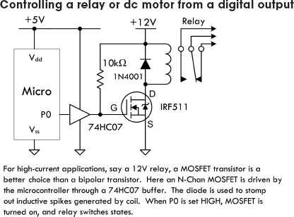
FIGURE 13.23
Pulse-Width Modulation
The schematic shown in Fig. 13.23 is also suitable for controlling inductive loads like dc motors. If the digital output is driven as PWM, then this circuit can also be used to control the power going to the motor, and hence its speed (see Fig. 13.24).
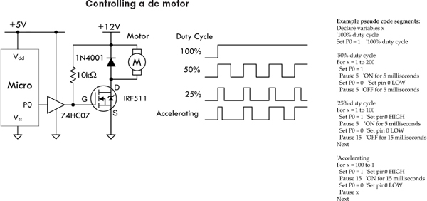
The waveforms on the right in Fig. 13.24 show how you can control the motor speed by adjusting the duty-cycle (proportion of time the power is on). The pseudocode on the right shows how this is accomplished. Note that some microcontrollers also have dedicated hardware support to simplify the process of generating PWM signals.
If your microcontroller has fairly robust output drivers, then there is probably little point in using the 74HC07 buffer.
Directional Motor Control
Directional control of motors can be achieved using an H-bridge, as shown in Fig. 13.25.
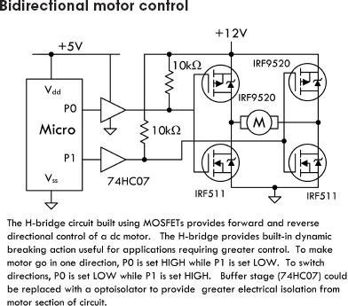
FIGURE 13.25
Most useful for controlling motor currents of less than a couple of amps are IC H-bridges such as the TB6612FNG, which combine all the transistors into one package. They often also have features such as thermal shutdown, to protect against overloading.
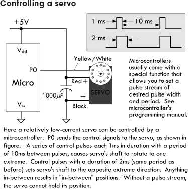
Servo Motor Control
We have already touched on controlling servo motors in our robot example project. Since the servo uses a control signal, this can be provided directly from a digital output (see Fig. 13.26).
Stepper Motor Control
A stepper motor has a number of coils that must be energized in the correct sequence to move the rotor. The arrangement shown in Fig. 13.27 can be used to accomplish this.
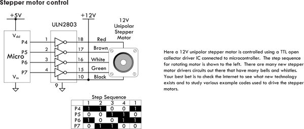
FIGURE 13.27
See Chap. 14 for more information about motors.
13.5.4 Sound Interfaces
Figure 13.28 shows a schematic for detecting sound. The second comparator stage is optional, and the output of the first stage could be fed directly into an analog input, allowing the sound to be sampled. Most microcontroller ADCs are not terribly fast, but even so, they should be able to sample at above 10 kHz, allowing some primitive digital signal processing.

When it comes to generating sound, being digital devices, few activities come more naturally to a microcontroller than generating a squarewave. All it needs to do is set a pin high, wait, set it low, then wait again, and keep repeating those steps. As demonstrated earlier in the chapter, both the Arduino library and the BASIC Stamp provide commands to do this directly. If you are using a piezo speaker, this can be driven directly from a digital output. If you are using a electromagnetic loudspeaker, then this will be beyond the drive capabilities of an output pin, and you will need to amplify the signal. For a range of audio amplifier circuits, refer to Chap. 15. But given that a squarewave sounds pretty harsh, then high-quality amplification is unnecessary, and a circuit like the one shown in Fig. 13.21, where the load is a loudspeaker, will work just fine. Make sure you do the math to check that the transistor can cope with the collector current, as most loudspeakers are 8 Ω.
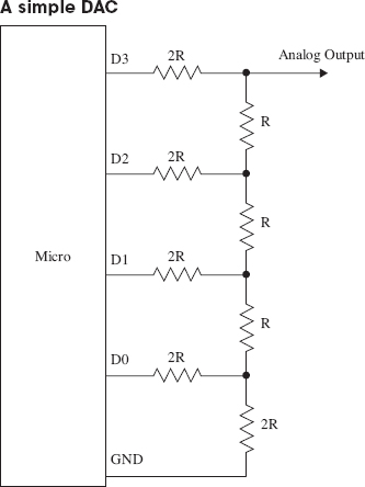
Generating a sine wave requires a bit of thought and effort. A first idea may be to use the PWM output of one of the pins to write out the waveform. However, the PWM switching frequency for most microcontrollers is at an audio frequency, so without a lot of care, the signal will sound as bad as a squarewave. A better way is to use a DAC, which has a number of digital inputs and produces an output voltage proportional to the digital input value. Fortunately, it is very easy to make a simple DAC—all you need are resistors.
Figure 13.29 shows a DAC using an R-2R resistor network. It uses resistors of a value R and twice R, so R might be 5 KΩ and 2R 10 KΩ. Each of the digital inputs will be connected to an Arduino digital output. The four digits represent the 4 bits of a digital number, so this gives us 16 different analog outputs. Higher-resolution DACs can be made by using more stages. Alternatively, DAC ICs, which can be more convenient to use, are available.
13.5.5 Serial Interfaces
There are a number of different standards for serial interfaces to microcontrollers, which use different numbers of pins and approaches to communication. In this section, we will explore some of them and look at how they can be used to connect things to a microcontroller.
When communicating with a peripheral, whichever serial interface it uses, there are a number of ways that the microcontroller might interact with the device. You may simply issue commands from the microcontroller, usually in the form of a 1-byte code that means something like “take a temperature reading,” or in the case of serial EEPROM, “store this data here.” The device then may respond with a result or value. Another common, but far less intuitive, approach is for the device to use registers, and some of the commands concerned with fetching and setting bits in the register that then control the electronics of the device. So, for instance, setting an I2C FM receiver IC to operate in stereo rather than mono involves setting the appropriate bit in a register using a general-purpose write-register command, rather than a command specific to setting the mode to mono or stereo.
1-Wire Bus
As the name implies, the 1-Wire serial bus uses just a single connection (apart from a common ground) to communicate. This standard was developed by Dallas Semiconductors and is used in a variety of sensors and other devices such as ADCs and EEPROM. It can operate at either 5 V or 3.3 V, so always check that a device you are connecting to your microcontroller operates at the same voltage. If it doesn’t, then damage may ensue.
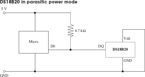
The DS18B20 temperature sensor uses the 1-Wire interface. This sensor was introduced in Chap. 6. In this chapter, we will look at how the sensor can be used in parasitic power mode, so that only two connections are needed from the microcontroller to the device. Furthermore, up to 255 devices can be connected to the same wire.
Figure 13.30 shows a DS18B20 attached to a microcontroller. 1-Wire devices act as either a master or slave. The microcontroller will be the master, and the peripheral devices, such as sensors, the slave. The slave devices contain a capacitor that is charged from the bus when no data is being transferred and used to power the slave device while the bus is being used for data. When the DS18B20 is being used this way, its GND and Vdd connections are tied together. The communication is two-way, so the microcontroller will use the pin as both an input and an output, changing the pin’s direction while the program is running. Every slave device has a unique 64-bit identifier that is programmed into ROM during manufacture.
Communication is always initiated by the master (microcontroller), which will put the data line into output mode and send a command as a sequence of pulses. The data line is pulled up to 5 V, so pulses are from 5 V to GND. A pulse of 60 μS signifies a 0, and 15 μS indicates a 1.
When the microcontroller needs to issue a command, it first sends a reset pulse of at least 480 μS, followed by the command sequence that includes the identifier of the device. The available device IDs are found by a special search protocol where the master sends a command that requests devices with a particular bit in their ID to respond. If more than one responds, then it tries another bit, and in this way, efficiently identifies all the devices.
Any microcontroller that you use with 1-Wire will have a library and example code for using the bus, so there is little point in looking at the low-level protocol. The following fragments of code illustrate how the Arduino OneWire library is used with a DS18B20.
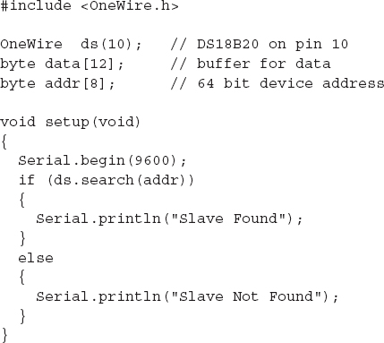
The first step is to include the OneWire library and define some byte arrays to hold the data and the device ID for the DS18B20. The setup function opens a serial port, so that the temperature readings can be sent to the Arduino serial monitor, and then searches for devices on the 1-Wire bus. There should only be one, and if it is found, then a suitable message is displayed.
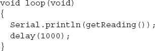
The main loop simply calls the function getReading, sends it to the Arduino serial monitor, and then pauses for a second.
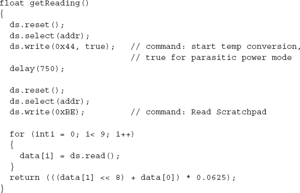
The getReading function is where most of the work goes on. It has two commands: one to start the temperature conversion and another to read the data resulting from the conversion.
Each command is preceded by a reset. Note how the slave to be communicated with is set using ds.select(). We then read the response into the byte array called data. To actually decode the temperature, we need only the first 2 bytes of the data, which are combined into a 16-bit integer and multiplied by the scaling factor (defined in the DS18B20 data sheet) as 0.0625.
Next, we have this line:
This first shifts the byte contained in data[1] left by 8 bits, and then adds in the lower 8 bits contained in data[0]. This results in a 16-bit integer that must be multiplied by 0.0625 to produce a temperature in degrees Celsius (see the data sheet for the DS18B20).
The resulting trace in the Arduino serial monitor should look something like Fig. 13.31.

We have touched on only two of the DS18B20’s commands. For a full list of commands and more information about the protocol, look at the DS18B20 data sheet (http://datasheets.maxim-ic.com/en/ds/DS18B20.pdf).
I2C (TWI)
On the face of it, the I2C, also sometimes known as the Two-Wire Interface (TWI), serves much the same purpose as 1-Wire, although it has two wires rather than one for data. Like 1-Wire, it is a bus and can support multiple devices connected to the same two wires. It also can run at either 5 V or 3.3 V. However, it is faster than 1-Wire, with top speeds of up to 400 kbits/s.
The two data lines of I2C are open-drain connections that operate as both inputs and outputs at the microcontroller. They must have pullup resistors in the same way as 1-Wire, but there is no equivalent to the 1-Wire parasitic mode, so remote sensors will generally require four wires in total: two for data and two for power.
Figure 13.32 shows how two microcontrollers might communicate using I2C.
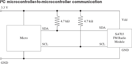
FIGURE 13.32
I2C devices are either masters or slaves, and there can be more than one master device per bus. In fact, devices are allowed to change roles, although this is not usually done. It is common for microcontrollers to have an I2C interface and use it to exchange data between microcontrollers.
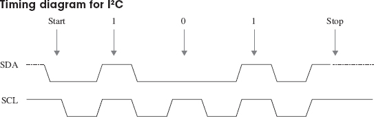
The serial clock line (SCL) is a clock, and the serial data line (SDA) carries the data. The timing of these pins is shown in Fig. 13.33. The master supplies the SCL clock, and when there is data to be transmitted, the sender (master or slave) takes the SDA line out of tri-state and sends data as logic highs or lows in time with the clock signal. When transmission is complete, the clock can stop and the SDA pin be taken back to tri-state.
Whether using I2C or 1-Wire, from a microcontroller, the code is likely to be similar, and a library is provided to hide the low-level timing of the protocol.
The following example, in Arduino C, shows I2C in action to send data from one microcontroller to another. When using I2C to interface with a sensor or other I2C slave device, the process is similar, but the messages will generally be packed into byte arrays. For this kind of application, every device will be different, and the data sheet for the device should be studied to determine the format of the messages that it expects. These examples are adapted from the examples provided with the Arduino environment. Thanks to Nicholas Zambetti for making this code public domain.
We start with the code for the transmitting microcontroller.
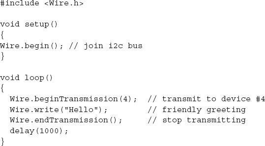
The transmission is very simple. We just say which device on the bus we want to send to, and then send it the data. In this case, the data is a string, but the write method can also take a single byte or a byte array as arguments for the data to be sent.
Receiving the data is a little more complex.
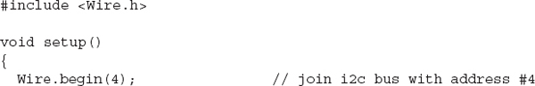
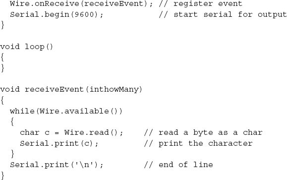
In this case, the receiver is a slave device and must identify itself—in this case, using the number 4 as its argument to Wire.begin. It then registers a function receiveEvent, which should be invoked whenever there is incoming data for this device. This function simply loops over each byte of data in the message, displaying it on the Arduino serial monitor.
Serial Peripheral Interface
Yet another microcontroller bus standard is the SPI bus. This one uses four data lines and is faster than the previous buses that we have looked at (up to 80 Mbits/s).
Figure 13.34 shows how a number of peripherals can be connected to the bus. Note that there can only be one master device.
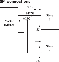
FIGURE 13.34
The slave devices are not assigned addresses. Instead, the master (usually a microcontroller) must have a dedicated Slave Select (SS) line for each of the slave devices, just selecting the one it communicates with. The other extra line is required because separate lines are used for each direction of communication. The Master Out/Slave In (MOSI) line carries the data from the master to the slave device, and the Master In/ Slave Out (MISO) line does the reverse.
Many different data protocols have been layered over the physical serial interface, but the basic principal is the same as for the other buses that we have looked at. The approach to take is to find the SPI library for the microcontroller that you intend to use and read the data sheet for the device you wish to communicate with.
The SPI specification does not define the bit order for sending data, so make sure that your code agrees with the device in this respect.
SPI is also used as a means of ICSP on some microcontrollers, such as the ATmega and ATtiny families.
Serial
Many devices use yet another type of interface called just serial. This is a very old standard with its roots dating back to the days of teletypes. Some computers with serial ports can still be found. In the “good old days,” people used to attach modems to them for communicating over phone lines with other computers.
The normal voltages used in the signals for serial ports conform to the standard RS-232 and use voltages that swing both positive and negative with respect to GND. This is not terribly convenient when using microcontrollers. For this reason, microcontrollers use the same communication protocol, but at logic levels. This is called TTL Serial, although more and more, it is being used by devices using 3.3 V rather than 5 V. See the next section for information about level conversion.
Electrically, TTL Serial uses two data pins: Tx and Rx (Transmit and Receive). It is not a bus, and the connection is point to point, so there are no problems with addressing different devices.
Another remnant from early computer history is the nomenclature around the bandwidth of serial connections. A serial connection must be set to the same baud rate at both ends of the connection. The baud rate is the number of bits per second, but that does include start, stop, and potentially parity bits, so the actual transmission of data is a little slower than the baud rate. To simplify matching up the baud rates at each end of the connection, a set of standard baud rates is used: 110, 300, 600, 1200, 2400, 4800, 9600, 14400, 19200, 38400, 57600, 115200, 128000, and 256000. Of these, 1200 is probably the slowest baud rate commonly in use, and many TTL serial devices will not go as high as 115200. 9600 is a very commonly used baud rate, and devices will often default to this rate, but be configurable to other rates.
As well as the baud rate, other parameters that define a serial connection are the number of bits per word, the type of parity bit, and the number of start and stop bits. Almost universally, these are defined as 8, none, and 1, respectively, which is often abbreviated to 8N1.
Bits are simply sent as high or low logic levels (see Fig. 13.35). As there is no separate clock signal, timing is critical, so after the start bit, the receiver will sample at the appropriate rate until it has read the 8 data bits and the 1 stop bit. The least significant bit of the data is sent first.
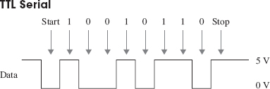
FIGURE 13.35
Most microcontrollers will either have dedicated hardware for TTL Serial (a UART) or manufacturer-developed software libraries for serial.
13.5.6 Level Conversion
There is a recent trend for microcontrollers and other ICs to use 3.3 V or even 1.8 V rather than 5 V. Lower-voltage devices use less current and can be more convenient to power from batteries. The same is also true of modules that the microcontrollers need to communicate with. While some 3.3 V devices can tolerate 5 V, many cannot. This means that if you are communicating with them using one of the bus and serial interfaces discussed previously, you will need to make sure that you convert voltage levels appropriately.
SPI and TTL Serial Level Conversion
Converting levels on SPI and TTL Serial is quite easy, because they have separate lines for each direction of communication. Figure 13.36 shows how resistors can be used as simple voltage dividers.
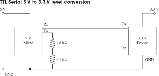
FIGURE 13.36
The Tx output of the 3.3 V device can be connected directly to the Rx input of the 5 V microprocessor, because it will see any input over about 2.5 V as a logical high anyway. The voltage divider is required when the 5 V Tx output of the microprocessor must be reduced to prevent damage to the 3.3 V device.
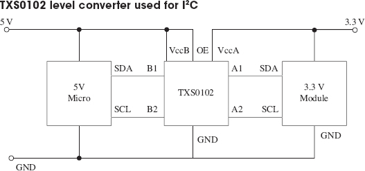
I2C and 1-Wire Level Conversion
The problem is more complex when pins change modes, from being an input and being an output, as they do with I2C and 1-Wire. In both these cases, the best solution is to use a custom level-shifting IC such as the TXS0102, which can convert two levels (ideal for I2C). Figure 13.37 shows the TXS0102 used to convert levels for I2C. Alternative ICs that perform the same role are the MAX3372, PCA9509, and PCA9306.
13.5.7 LED Display Interfaces
LED displays made up of a number of LEDs encapsulated in a single package can be a challenge to control. Such displays will normally be controlled using a microcontroller, however, it is not necessary to use a microcontroller to pin each individual LED. Instead, multi-LED displays are organized as common anode or common cathode, with all the LED terminals of the anode or cathode connected together and brought out through one pin. Figure 13.38 shows how a common anode seven-segment display might be wired internally.
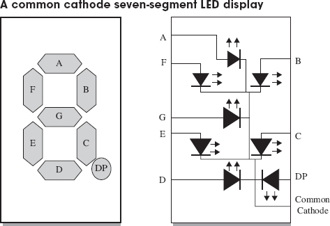
FIGURE 13.38
In a common cathode display like this, the common cathode would be connected to ground, and each segment anode driven by a microcontroller pin through a separate current-limiting resistor. Do not be tempted to use one resistor on the common pin and no resistors on the noncommon connections, as the current will be limited no matter how many LEDs are lit, and so the display would get dimmer as more LEDs were illuminated.
Multiplexing LED Displays
It is quite common for multiple displays to be contained in the same case. For example, Fig. 13.39 shows a three-digit seven-segment common cathode LED display. In this kind of display, each digit of the display is like the single-digit display of Fig. 13.39 and has its own common cathode. But, in addition, all the A segment anodes are connected together, as is each segment.
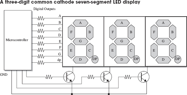
The microcontroller, or LED driver IC, using the display will activate each common cathode in turn, turn on the appropriate segments for that digit, and then move on to the next digit. This refresh happens very quickly, so that the display appears to show different numbers on each digit. This is called multiplexing. The same approach can be used with LED matrices, where each column is activated in turn, and then the appropriate pins are set for the rows of that column.
Note the use of transistors to control the common cathodes. This is simply to handle the current of potentially eight LEDs at once, which would be too much for most microcontrollers.
Charlieplexing
When looking to minimize the number of pins used to display a matrix of LEDs, an interesting technique called Charlieplexing can be used. (The name comes from the inventor Charlie Allen at Maxim.) This technique takes advantage of the feature of modern microcontroller I/O pins that allows them to be changed from outputs to high-impedance inputs while a program is executing. Figure 13.40 shows the arrangement for controlling six LEDs with three pins.
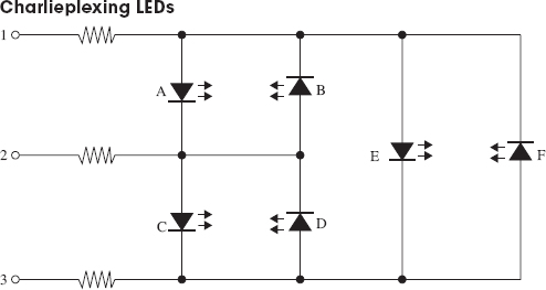
FIGURE 13.40
Charlieplexing is a dynamic activity, so rather like multiplexing, not all the LEDs that you want to be lit are lit at the same time, but they will appear lit as the display is refreshed faster than the eye can keep up. To do this, the pins will be high, low, or high impedance input, as shown in Table 13.9.
TABLE 13.9 Charliplexing LED Addressing
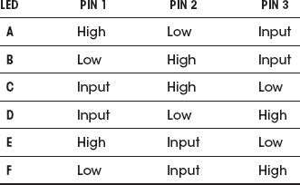
The number of LEDs that can be controlled per microcontroller pin is given by the following formula:
LEDs = n2 – n
So, if we use 4 pins, we can have 16 – 2, or 12, LEDs, and 10 pins would give us a massive 90 LEDs. However, there are problems with scaling Charlieplexing up. One is due to the fact that the refresh rate needs to be fast enough to fool the eye, and a large number of pins will need a lot of sequence steps to energize all the LEDs that need energizing in a refresh cycle. This will also result in the LEDs becoming dim, as their duty cycle will be low. You can compensate for this to some extent by increasing the current through the LEDs, which will cope with fairly large peak currents for a small duration. This does lead to the problem that if the microcontroller freezes for some reason, the LEDs could burn out.
Controlling the Color of RGB LEDs
RGB LEDs are actually three LEDs in one package (one red, one green, and one blue). The package will often be common anode or common cathode. By controlling the power to each of the LEDs separately, it’s possible to set the overall color of the LED module to any color at any intensity.
While you could change the intensity of each color channel by controlling the current to the LED in an analog fashion, it is far better to control it with a PWM signal. The duty cycle will control the brightness of the LED in a far more linear manner than controlling the current in an analog fashion.
..................Content has been hidden....................
You can't read the all page of ebook, please click here login for view all page.