
Marine Power Generation Technologies
Abstract
There are four ways in which the world’s oceans can provide an energy source for power generation. Marine currents around coastlines, inlets, and estuaries can be exploited with underwater turbines. Ocean waves are also a source of energy that can be tapped using a variety of different devices that convert the oscillating motion of waves into a motion that can be used to provide electricity generation. The world’s oceans, particularly in the tropical regions, are massive solar collectors, absorbing heat that creates a hot layer on the surface of the sea. This hot water can be used to drive a heat engine, with cooling taken from the ocean depths where the temperature remains low. The mixing of fresh and salt water also releases energy, and this too can be tapped in a number of ways to generate electricity. All of these are being developed as means of power generation.
In the search for sources of electric power to replace fossil fuels, technologists have explored all the natural phenomena that might be exploited to generate electricity. As a consequence, wind power, solar power, and biomass-based generation are today becoming mature technologies alongside hydropower. However, one potential source of energy has yet to exploited commercially—the energy contained in the seas and oceans.
Part of the reason for the slow advance of marine power generation is the hostile environment in which marine energy conversion devices have to operate. The development of power generation technologies that can withstand these conditions requires great tenacity and it has not always been clear that the seas can yield an economical means of generating power. In spite of this technologists have persevered, and while marine power generation remains at the development and demonstration stage, there is greater confidence today than there has ever been that it will produce results in the near future.
There are four ways in which energy can be extracted from the seas to provide power generation. Perhaps the most significant today, because it is the easiest to exploit, is the energy provided by marine currents. These currents are generated by tidal movements and are normally found in estuaries and around rock formations close to shore. Energy can be extracted from them by using underwater turbines that are conceptually similar to wind turbines.
Sea and ocean waves offer the second source of energy. Waves are generated by the wind and like the wind they are erratic, but it is possible to exploit the energy they contain with devices of various kinds, some mounted close to the shore, some in deep water, some floating, and some anchored to the seabed. This is potentially the most difficult marine energy source to tap but there is a significant resource available if it can be mastered.
The third source of marine energy is provided by the sun. The world’s seas, particularly those in the tropics, are massive solar collectors absorbing heat energy throughout the day. This absorption creates a layer of hot water at the sea’s surface, while below the surface the water temperature is much lower, creating a temperature gradient that can be exploited to drive a heat engine. The technique is known as ocean thermal energy technology (OTEC).
The fourth source of energy is probably the most unexpected. When fresh water from a river reaches the sea and mixes with salt water, energy is released. This energy of dilution is predicted by classic thermodynamics, and in the past decade one or two pilot projects have sought, with some success, to take advantage of this as a way of producing electricity. Today this resource is referred to as salinity gradient, and while it is immature, it does offer future promise.
Marine energy resource
To arrive at an estimate for the size of the global marine energy resource it is necessary to make assumptions about the actual amount of energy that each type of resource contains and the efficiency with which it can be extracted. Producing such estimates can be a challenge for resources as widely distributed and as difficult to define as these, but attempts have been made. Some are shown in Table 14.1. The table contains figures for the annual energy that might be extracted from each resource based on figures from the International Energy Agency (IEA), and figures for the potential generating capacity each might yield, based on research from Powertech Labs.
Table 14.1
Marine Energy Resources
| Marine Energy Resource | Potential Annual Energy Available | Potential Generating Capacity |
| Tidal current | 800 TWh/y | 5000 GW |
| Wave power | 80,000 TWh/y | 1000–10,000 GW |
| Ocean thermal energy technology | 10,000 TWh/y | 2600 GW |
| Salinity gradient | 2000 TWh/y | 2000 GW |
Sources: Ocean Energy, Opportunity, Present Status and Challenges, International Energy Agency/Ocean Energy Systems, 2004–2006; and G. Bhuyan, Ocean Energy: Global Technology Status, Opportunities and Challenges for Canada, Powertech Labs Inc., 2005.
The largest resource based on the IEA figures is wave power that could, in principle, provide up to 80,000 TWh of energy each year. OTEC is the next largest with a potential 10,000 TWh/year, followed by salinity gradient with 2000 TWh/year, and finally tidal current that could yield 800 TWh/year. Other estimates provide significantly different values so these should be used for broad guidance only. In terms of the generating capacity each might support, wave power is again the largest, potentially, with up to 10,000 GW. Tidal current might provide 5000 GW, OTEC 2600 GW, and salinity gradient 2000 GW. Based on these evaluations, even the smallest could potentially provide a significant contribution to global power generation.
Of the four resources, tidal stream has the smallest potential, but because the currents that make up the resource are located close to shore, it is perhaps the easiest to exploit and so the generating capacity it might provide is relatively high. The existence of tidal currents depends critically on local topologies and some regions have much better regimes than others. The U.K. coastline is estimated to hold around 40 TWh/year, and in Alaska perhaps 100 TWh/year could be exploited.
There are other ocean currents that are not caused by the tides, such as the Gulf Stream that operates in the Atlantic Ocean. This could perhaps be exploited too using the technology for tidal stream energy capture. Estimates from Florida State University suggest that 8 GW of generating capacity could be installed to extract energy from the Gulf Stream as it passes the Florida coast. Capturing energy from the Gulf Stream in the deep ocean would be more difficult.
Waves are generated when the seas absorb energy from the wind. The longer the reach over which the wind can blow, the more energy is absorbed and the greater the wave energy available. As a consequence, the best wave regimes are found where prevailing winds can blow across long stretches of open sea. Once created, waves will travel long distances, and they contain more energy in deep water than in shallow water where they shed energy as they approach the shore.
The largest waves are usually found between 30° and 60° of latitude (hence the name ‘the roaring forties’ for the region in southern hemisphere where westerly gales blow throughout the year), but there is also a good wave regime in some regions between 30° of latitude and the equator and also in southern polar waters. Regionally, the best locations for wave power exploitation are found on western coastlines along North and South America, in western Europe and western Africa, and the western coasts of Australia and New Zealand.
OTEC energy is found where seas absorb the heat from the sun. As a consequence, the greatest resource is in tropical regions in the seas close to the equator. Much of this thermal energy is far out to sea and difficult to exploit except with floating plants. Shoreline exploitation is possible, but to use the heat in coastal surface waters, an OTEC plant must also have access to deep, cold waters. A depth of a 1 km is generally needed to provide an adequate temperature difference between the hot and cold sources to drive an OTEC heat engine economically. Shore sites with deep offshore waters close enough to the shore to be accessible are rare.
To generate power from the mixing of fresh and salt water it is necessary to have a source of both close together. This situation can generally only be found at the mouth of a river. In principle, high-salinity seas such as the Dead Sea could also provide energy in this way, but exploitation would involve bringing in fresh water and diluting the saline source, which might have significant environmental consequences.
Ocean thermal energy conversion
OTEC takes advantage of the temperature difference between the sea surface and the deep sea or ocean to drive a thermodynamic heat engine that can generate electricity. The best regions for OTEC are usually found within 20° of the equator. Here the surface water temperature can rise to between 25 °C and 33 °C. The hot surface water does not mix with deeper water, so there is a significant temperature gradient between the surface and lower strata. The latter can remain at a temperature of only 9 °C at a depth of 500 m and below 5 °C at a depth of 1 km.
The amount of energy absorbed by tropical oceans is enormous. Estimates from the U.S. National Renewable Energy Laboratory suggest that across the 60 million km2 of tropical ocean an amount of energy equivalent to as much as 250 billion barrels of oil/day is absorbed. If only a small fraction of this could be converted into electrical power it would provide a massive resource.
An OTEC plant requires a temperature gradient of 20 °C to be able to operate effectively. This means that a surface temperature of 25 °C will normally be necessary and access to colder waters at 5 °C or less. To access this cold water, an OTEC plant must be able to reach at least to 500 m below the sea surface, and for efficient operation it will normally need to pump water from as much as 1000 m down.
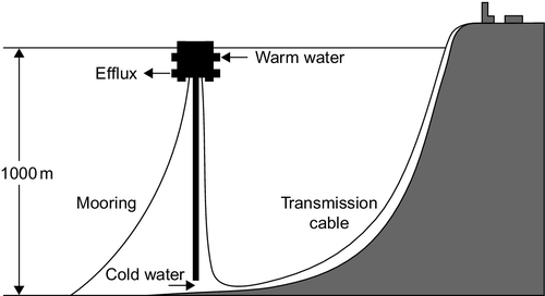
A land-based plant, even with deep water close to the shore, is likely to require a pipe of at least 2 km in length to reach sufficiently cold water. The alternative is to build the OTEC plant on a floating platform that is tethered offshore with the cold water pipe hanging from the support, and then carrying the power to the shore via a seabed cable (Figure 14.1). Even with this arrangement, the platform may have to support a pipe of 1 km in length. More generally, if OTEC is to provide anything more than very small amounts of power, plants will need to be able to operate in the open sea where they will have to support a pipe capable of pumping water from up to 1 km below the surface.
OTEC plants not only produce electricity, some configurations can also generate drinking water, which can improve their economics, particularly for small island communities that have little local fresh water. In addition, the cold water that the OTEC plant draws from the ocean depths is rich in nutrients so it can be used to provide an environment for aquaculture. The combination of electricity generation, potable water production, and aquaculture could make multipurpose OTEC systems economically viable in the future.
The OTEC cycle was first proposed by in 1881 Jacques-Arsène d’Arsonval, a French physicist and physician, although the idea was earlier outlined by the author Jules Verne in his book Twenty Thousand Leagues Under the Sea. D’Arsonval based his system on a closed-cycle ammonia turbine but never realized his scheme. It was not until 1979 that a project of the same type was built in Hawaii with a net output of 18 kW. Before this, in 1930, a student of d’Arsonval called Georges Claude built a 22 kW OTEC plant based on an alternative open turbine cycle. This plant consumed more energy than it produced and was not commercially successful.
OTEC was revived during the 1970s but the economics have remained difficult. One of the problems is the vast quantity of cold water that must be pumped from a great depth below the surface of the sea. This requires a lot of energy. The volume of water involved for a 100 MW plant is around 200 m3/sec. To deliver this would require a pipe of around 11 m in diameter and as much as 1 km long. Meanwhile, the discharge of both hot and cold water from a 100 MW plant would be roughly 600 m3/sec, one-sixth of the flow from the Nile River into the sea.
OTEC Technology
OTEC relies on a very small thermal gradient to drive a heat engine and generate electrical power. The efficiency of a heat engine increases the larger the temperature difference between the hot and cold sources. For a temperature difference of just 20 °C the best theoretical efficiency is 6.6%, rising to 9.6% with a 30 °C temperature difference. Practical efficiencies are likely to be lower than this, and when the power required to pump water from the ocean depths is taken into account, the overall efficiency may fall to 4% or less. As an example, a practical system designed by Lockheed Martin operating with a temperature difference of 18.5 °C recorded an efficiency of 2.65%.
There are two primary cycle types that can be used to exploit this small temperature difference; a closed cycle and an open cycle. The closed cycle system uses a special thermodynamic fluid that is alternately vaporized and condensed as it cycles within a closed turbine system. The most common working fluids for this type of cycle are either a low–boiling point organic fluid that can be easily vaporized using hot seawater, or an ammonia or ammonia-and-water mixture. An organic working fluid will generally be exploited using a Rankine cycle turbine system while the ammonia–water working fluid is commonly found in a Kalina turbine cycle. Both are capable of generating power from small temperature differences.
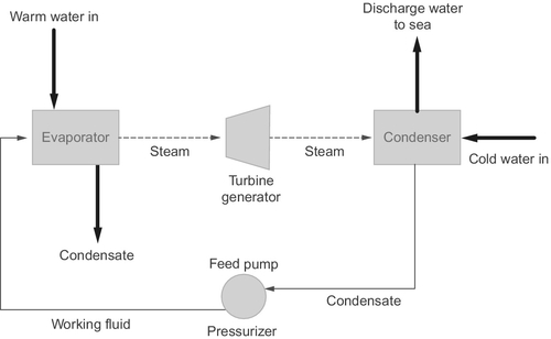
In a closed cycle system the pressurized working fluid is heated and vaporized by passing it through a heat exchanger through which the hot sea water passes (Figure 14.2). The vapor produced in the heat exchanger is used to drive a turbine. The vapor exiting the turbine is then condensed using cold seawater in a second heat exchanger before recycling through the first heat exchanger. The difference in vapor pressure between the hot and cold heat exchangers provides the pressure difference that drives the turbine. The turbine then drives a generator to produce electrical power.
The heat exchangers are the most critical components of a closed cycle OTEC plant and they determine if it can operate economically. For high efficiency, the heat exchangers must be very large; a pilot 1 MW plant tested in India in the early part of the first decade of the 21st century included an evaporator, or hot water heat exchanger, with an area of around 4000 m2 that accounted for 27% of the cost of the plant. As a consequence of the large size necessary, economies of scale demand that such plants must be large to be economical. Closed cycle OTEC plants are unlikely to be viable at sizes less than 40 MW.
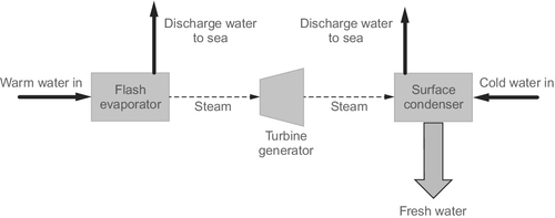
The alternative, open cycle OTEC plant does not use a special thermodynamic working fluid but instead uses seawater itself (Figure 14.3). Warm seawater is injected into an enclosure called a flash evaporation chamber that is held at low pressure. Inside the flash chamber a part of the seawater vaporizes and this vapor (steam) is fed into the turbine. After passing through the turbine, the vapor is then condensed in a heat exchanger using cold seawater, creating a pressure gradient that provides the power to drive the turbine.
Flashing seawater in this way produces a vapor between one and three times atmospheric pressure—very low by steam turbine standards. Exploiting this requires a very large steam turbine. Meanwhile, the low pressure in the flash chamber is generated hydrostatically by siting the chamber above sea level so that a head of water to the sea can create a negative pressure.
It is difficult to build an open cycle OTEC turbine with a capacity greater than 3 MW using conventional materials because of the size of the turbine involved. Higher capacities might be achieved with lightweight materials such as those used for wind turbines, and turbines with diameters of 100 m have been proposed. However, it is not clear today that the economics can support the research necessary to develop such turbines. One of the key attractions of an open cycle OTEC plant is that the condenser provides fresh water that can be used for drinking. This might make a plant economical under some circumstances.
It is possible to combine the advantages of open cycle and closed cycle plants in a hybrid plant. Here warm seawater is flashed to produce vapor but the warm vapor then vaporizes, in turn, the working fluid in a closed cycle OTEC system. Both vapors are then condensed using cold seawater. As with a conventional open cycle plant, the hybrid plant can provide drinking water from the water vapor.
While OTEC plants would ideally be built on land, suitable sites are scarce and most of the resource is located far from land in the tropical oceans. To extract this energy requires floating OTEC plants that “graze” the oceans to generate power. Since they would be located far from land, they would then have to store the energy they produced. This might be achieved by converting the electricity into hydrogen via electrolysis of seawater. The approach could become attractive if a wider hydrogen economy develops, but today it is difficult to make an economic case for such a project.
Since the beginning of the 1990s a number of close-shore commercial projects have been proposed, the latest being a scheme to build a 10 MW offshore plant to power a low-carbon resort off the coast of China. This plant would be constructed by Lockheed Martin, which has been developing an offshore OTEC design for several years. However, at the beginning of 2013 no commercial plant had actually ever been built.
One of the main problems with OTEC is environmental. The plant must draw enormous quantities of cold water from the ocean depths, but if this is returned to the surface, it will result in the mixing of sea strata, a cooling of the surface water, and a big increase in the level of nutrients. The consequences of this for local marine life have yet to be assessed. The alternative—returning the water to the same depth as it was extracted—will affect plant economic viability since it will require more pumping, an energy-intensive activity.
There is also the danger that water from the deep ocean will release carbon dioxide dissolved within it when it is brought to the surface. Against this, it has been argued that this nutrient-rich water will encourage marine flora and that this will absorb more carbon dioxide. Only large-scale development will enable these questions to be answered definitively.
Wave power
The waves found in seas and oceans are created when the sea absorbs energy from the wind. The stronger the wind and the longer the reach of sea over which it has to blow, the greater the amount of energy that is absorbed. The rotation of Earth means that the best wind regimes are generally found on western shorelines exposed to the wide ocean and the strongest winds are between 30° and 60° degrees of latitude. Good sites can be found along the western coasts of Europe, North and South America, Africa, Indonesia, Malaysia, New Zealand, and Australia.
The energy contained within waves is manifested as an oscillatory motion of the sea surface. Over very long reaches this can assume a regular frequency, as characterized by the swell found on the oceans, but often and particularly near the coast it will become a superposition of a number of different frequencies. Whatever its precise nature, the motion from the point of view of energy capture is an oscillation of the water surface relative to a fixed point on land or on the seabed. It is this motion that must be exploited in a wave energy converter. (Some converters also exploit the relative motion of two adjacent points on the surface.)
Wave energy is characterized by the amount of energy contained within a 1 m wave front as it arrives at the point of capture. Far out to sea, waves can contain as much as 100 kW/m, and this energy is retained while the waves remain in deep water but the energy content generally falls as the waves approach the coast. At a depth of 20 m, the energy content will typically have fallen by two-thirds.
Average annual wave energy levels along the coast of western Europe are 48–70 kW/m, and in the Americas they can range from 13–102 kW/m with the highest energy levels generally found in the more northerly or southerly parts of those continents. Energy content varies seasonally too, with more energy generally found in winter than in summer.
The possibility of harnessing waves as a power source was first explored during the 19th century, initially as a means of ship propulsion but later as a land-based means of energy capture. The earliest actual wave power machines were built in California between 1890 and 1910 when several “wave motors” were constructed though most were unsuccessful. After this, interest died until the 1970s when projects were launched in the United Kingdom, Japan, and Norway. None of these schemes appeared to be economically viable but interest grew again during the 1990s, and during the first decade of the 21st century, scores of new projects were launched using a wide range of differing technologies. Most are at an early pilot or demonstration stage but interest remains high.
Wave Power Technology
The quest to exploit the oscillatory motion of waves has given birth to a bewildering range of mechanical devices designed to convert that motion into electricity. Some of these are shore based, and some will only operate far out to sea. The principles upon which they operate vary widely too and there is no easy way to classify them.
Shoreline devices include oscillating water column converters and a range of overtopping devices. Oscillating flap converters are usually built close to the shore too. Offshore devices include floats, point absorbers, and wave pumps, all of which need to be tethered to the seabed to operate. Another series of offshore devices, with names such as snake and duck, use the relative motion of a series of floating elements, one against the other as a source of energy. There are also piezoelectric devices that generate electrical energy through the bending of a special material. These can be both shoreline and offshore energy converters.
Shore and Near-shore Wave Converters
Oscillating Water Columns
One of the simplest and most common methods of capturing energy from wave motion is with an oscillating water column (OWC) device (Figure 14.4). This comprises a tube or chamber that has a lower aperture below sea level and the opposite end above sea level, open to the air. The simplest way of envisaging an OWC is to think of a tube with one end immersed in the sea. As waves pass across the tube, the water level within it will rise and fall, alternately forcing air from the top of the tube or sucking it in. This motion of air can be harnessed to turn a type of wind turbine, generating electricity.
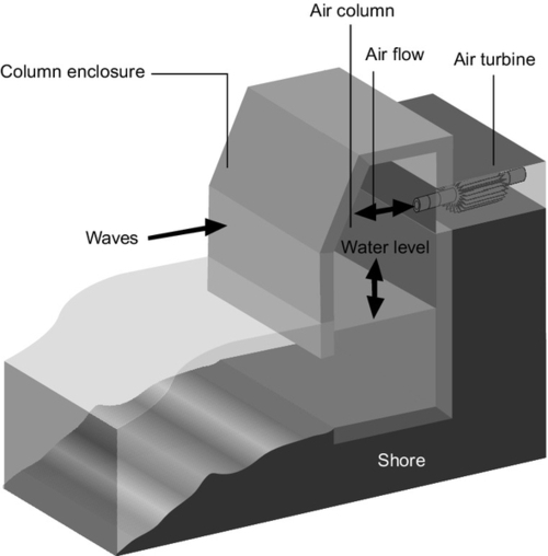
Since the movement of air is cyclic, alternately traveling in and out of the tube as waves pass, a conventional turbine would rotate first one way and then the other, and so it would be unable to generate with a conventional generator. There are two solutions to this. The first is to employ a system of valves and two turbines, one that rotates as air is forced from the tube and the other that rotates when air is drawn in. A more elegant solution is to use a turbine that can rotate in the same sense whichever direction the air flows. The most commonly used of these is a Wells turbine.
OWC devices can either be built on the shore or in shallow near-shore waters. They usually comprise some form of concrete structure anchored to the seabed or shoreline with seawater admitted to an aperture in the part beneath the water level. The device must be large enough so that its lower aperture is always submerged whatever the state of the tide. Otherwise, it will not be able to generate throughout the tidal cycle.
The energy source driving an OWC is variable and conversion into electrical power results in a highly variable output. If the turbine is designed with a significant moment of inertia this can help smooth the output but it will remain highly variable without further smoothing.
A variety of pilot-scale OWC energy converters have been built including a 500 kW unit called the Limpet that was built on the Scottish isle of Islay by a company called Wavegen in 2000. Since then a 4 MW has been proposed involving 30–40 Wells turbines. This project was to be built at Siadar Bay, on the island of Lewis in Scotland, but the project was canceled in 2012.
Overtopping Devices and Tapered Channels
Another simple method for extracting energy from waves is to consider them simply as a variable head of water. If some of the water from the crests of waves can be captured it can be used to create a head of water that rises above the surrounding sea level, and this can then be exploited to drive a hydroturbine and generate power with the water from within the device running back to the sea.
Creating a head of this sort can be achieved in a number of ways. One of the early attempts, called a Tapchannel, funneled waves into a rising and narrowing channel where the kinetic energy of the waves was used to force water to overflow the sides of the channel into a small reservoir built on the seashore. The water was then allowed to run back to the sea through a turbine.
Another approach is to build an offshore reservoir in shallow waters with gently sloping sides so that the energy of the waves as they drive toward the shore forces water to flow over the sides of the reservoir (Figure 14.5). As with the Tapchannel, the water collected in this way is then allowed to flow back to the sea through a turbine.
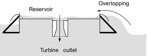
The head of water created in this way is relatively small and a low-head turbine is required to extract energy from it efficiently. Kaplan turbines have been used successfully in some pilot schemes of this type.
One of the overtopping devices currently being developed is the Wave Dragon. This was originally developed by a Danish company of the same name. Wave Dragon Wales won funding in 2011 to build a 7 MW prototype off the Welsh coast of Pembrokeshire. However, in 2013 the energy converter was still not constructed.
Oscillating Flaps
A third common near-shore wave energy converter is the oscillating flap device, sometimes also called an inverted pendulum converter (Figure 14.6). The basic principle behind this type of converter is to devise a buoyant flap, the bottom of which is hinged and attached to a foundation anchored to the seabed. The body of the flap then rises under water above the hinge. As waves move across the site of the device, they cause the flap to oscillate backwards and forwards and this oscillatory motion is converted into electrical power.

A similar principle can be exploited using a foundation structure that rises close to the surface of the sea. In this case the structure supports a weighted flap that is hinged from the top and falls down into the sea. Again, as waves cross the site of the device they cause the flap to move backwards and forwards.
Energy conversion with such devices is often carried out by using the oscillating motion to power a pump that drives a fluid, often seawater, under pressure through a pipe to the shore. A high-pressure flow of water of this type can then be converted into electricity using a Pelton turbine, normally used for high-head hydropower plants. With a system of this type, several wave energy converters can be used to provide pressurized water to a single turbine. In addition, water can be stored under hydrostatic pressure in an accumulator, allowing this type of wave energy device to store energy and smooth its output, providing a more valuable source of power for the grid.
One oscillating flap device that has been under development is the Waveroller, from Finnish company AW-Energy. The company deployed a pilot scheme off the Portuguese coast in 2012 comprising three 100 kW Waveroller oscillating units. The company is hoping to be able to use the pilot to develop a 500 kW commercial unit. A second oscillating flap device called the Oyster has been developed by U.K. company Aquamarine Power. A single 800 kW demonstration unit was installed at the European Marine Energy Centre, Orkney, in 2012. This uses the pump principle to bring pressurized water ashore to drive a hydroturbine.
Offshore Devices
Buoyancy-based Devices
One of the principal categories of offshore wave energy converters is based on a floating device such as a buoy that is tethered to the seabed. While such devices can operate close to shore, since the energy contained in waves is greater farther offshore they are better deployed in deep water.
A buoyancy device will be attached to an anchor that is fixed to the seabed. The device itself will then float to the surface, or it might be held just below the surface. In either case, the passage of waves will create an oscillating force acting on the buoy as passing waves pull it toward the surface and away from the seabed. This force is then used to generate electricity.
The force can be converted into a useful form of energy in a number of ways. One method involves installing a flexible hose as part of the tethering anchor. This hose is alternately stretched and released as waves pass, applying a pressure cycle to the tether. The motion causes the tube to contract and expand, and this can be used to generate a hydrostatic pressure that can be converted into electric power. Another, similar, approach is to use a piston pump fitted to the tether or buoy. The movement of the buoy up and down drives a piston in and out of a cylinder integrated into the device and this can be used to generate hydrostatic pressure too.
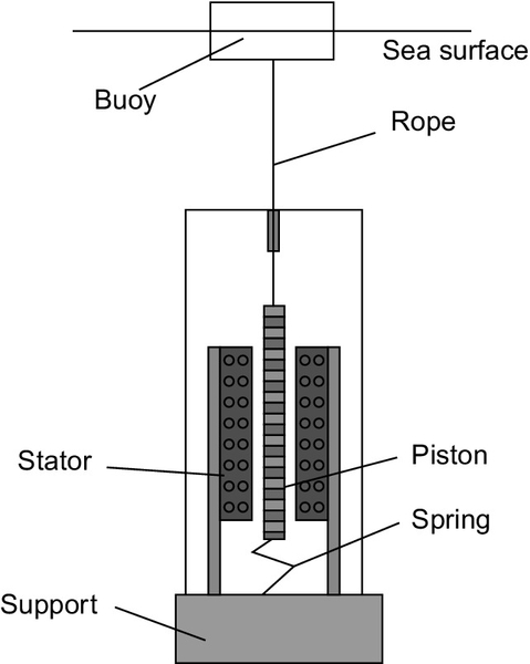
The main alternative to using the motion to pump water is a linear generator. This is a device that can produce electricity from linear rather than rotary motion (Figure 14.7). If a generator of this type is fitted into the tether of a buoy, the up and down motion as the buoy is lifted and dropped by waves can then be turned directly into electrical power.
Pontoons, Snakes, and Ducks
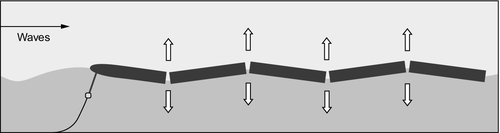
The second principal category of offshore wave energy converters comprises a disparate group of machines that have one thing in common. Each is made up of a number of floating sections that are joined end to end through a hydraulic linkage. When one of these devices is taken out to sea the sections will move relative to each other and this relative motion is used to extract power.
One of the earliest wave power devices, called the Salter’s Duck after its inventor, Stephen Salter, was a converter of this type. Devised in the 1970s, it comprised a large anchored section to which was fitted a lighter hinged “beak.” When moored offshore, wave motion caused the beak to oscillate up and down and this motion was exploited to provide power.
Some devices of this sort are made up of two or more elements of the same size. The relative motion of these as they jostle under the influence of the waves at sea then allows power to be extracted. Others are designed with one large, relatively immobile element and another that is tuned to respond to the motion of the waves. This latter group is often called point absorbers and they may be tethered to the sea bed, like buoyancy devices, above. Tuning a device in this way will normally mean that it only responds to a band of wave frequencies and is unaffected by others outside this band. Whatever the design, however, the principle is the same: one part of the device moving relative to the other, as shown in Figure 14.8.
As with other offshore devices, energy can be extracted by using the motion to pump water, by generating hydrostatic pressure that can be used to produce electricity, or by using some sort of linear generator. An example of this latter approach is the Archimedes Wave Swing, an underwater tethered buoy that was originally developed in The Netherlands but is now owned by U.K. company AWS Ocean Energy. A 2 MW prototype was tested off the Portuguese coast in 2005 where it achieved an output of 1 MW. More recently, AWS Ocean Energy has been awarded £3.9 m to build its latest prototype.
Another tethered buoy is the Powerbuoy being developed by U.S. company Ocean Power Technologies. Like the Archimedes Wave Swing this is a point absorber tuned to extract energy from ocean waves. The company has tested several prototypes but is currently developing what is proposed to be its first commercial deployment off the coast of Oregon. This will initially involve one 150 kW unit followed by 10 grid-connected units providing a total of 1.5 MW. Following this, the company plans a 50 MW installation. Factory testing of the first unit was completed in mid-2012.
Yet another tethered buoy is the Aquabuoy, in this case a floating device, which has also been tested off the coast of Oregon. There were plans for a 2 MW grid-connected power plant selling power to a U.S. utility but there have been no recent reports of progress.
Of the second type of offshore floating devices, the main example today is the Pelamis developed by Pelamis Wave Power. This comprises a series of buoyant cylindrical sections linked through hydraulic joints. Movement of the sections pumps oil that is used to drive a generator. A 750 kW prototype comprising three 250 kW units was deployed off the coast of Scotland in 2005, and in 2008 three units were installed off the Portuguese coast but had to be brought back ashore later that year. Since then there appear to have been no further units installed.
Piezoelectric Devices
Piezoelectric materials produce an electric voltage when they are placed under stress. This may be a result of bending, stretching, or a variety of other means including when they are subjected to vibrations. Any and all of these means of generating electricity could potentially be exploited in a wave energy device.
One idea that has been put forward involves piezoelectric “seaweed.” Wafers of a piezoelectric material are anchored to the seabed so that the wash of waves across them causes them to bend backwards and forwards, generating electricity. A second involves the stretching of a piezoelectric material that could, in principle, be used to generate power from a tethered buoy if the generator was mounted into the tether. However, while there are a wealth of possible ways such materials could be used, no wave converter using them has yet been built.
Marine current energy
Marine current converters, sometimes also called tidal stream converters, utilize the energy contained in flowing water generated by the motion of the world’s tides as a source of electrical power. Currents of this type can be found in many estuaries around the world and also in coastal straights and areas where there are offshore coastal features that allow the tidal movement to create a significant current. In principle, the same type of converter can be used in a river, too, as an alternative to a conventional hydropower plant.
The amount of energy that is available in a marine current depends on both the amount of water that is moving and the speed at which it flows. Areas where there is a large tidal reach are likely to offer the best marine current potential since the volume of water moving on each tide will be large. Meanwhile, the faster that water flows, the greater the energy it contains.
The energy that flowing water contains varies as the third power of its velocity so energy content is extremely sensitive to speed. A site with a fast current will therefore offer the most efficient way of harnessing this source of energy. Such sites may be found where the natural flow is constricted either in a river or offshore. Average flow rates of 2 m/s or more are generally considered ideal for a marine current power plant.
While some marine current plants may take energy from flowing river water, most will exploit tidal motion. The latter is both cyclical and variable, with the strength of the current depending on the state of the tide. This needs to be taken into account when designing a marine current project. There will be a small seasonal change too as the tides vary between spring and neap tides (the two extremes when the gravitational pulls of the moon and the sun either reinforce or oppose one another). The flow in river sites, on the other hand, will have little short-term variability but may vary significantly from summer to winter.
Flowing water is conceptually similar to flowing air. In consequence, the most common methods of extracting energy are similar to those developed for wind power—that is, turbines with several blades that rotate in the flow. However, because water is much denser than air, the energy density of flowing water is much greater so turbines can be much smaller for the same power output. For example, a 10 m diameter turbine in water flowing at 4 m/s can generate around 880 kW, whereas a 10 m wind turbine turning in a wind speed of 4 m/s would barely achieve 0.5 kW. For a similar output, the wind turbine would need to have a diameter of around 70 m.
In a 2 m/s flow of water an 18 m diameter turbine is needed to sweep out (or intersect) water carrying a power density of 1 MW. At 4 m/s the turbine size needed to sweep out a power density of 1 MW falls to 6 m. Only around one-third of the energy swept out is captured and converted into electricity, so for a 4 m/s flow a 1 MW marine generator would need to be a little more than 10 m in diameter.
Marine Current Energy Converters
Based on the analogy with moving air, most marine current converters are turbines that rotate in the water flow, providing a mechanical power output that can be converted into electricity. Many exploit technology similar to that used by the wind industry. The conventional wind turbine in use today is a horizontal-axis wind turbine mounted on the top of a tall tower. Exactly the same type of technology can be used for marine currents with, in this case, the tower fixed to the sea or riverbed.
It is possible to carry this analogy too far and there are often significant differences between wind and water turbines, particularly concerning the means of mounting the latter in the water flow. While all wind turbines are placed on towers, marine current turbines can be mounted on towers, they can be hung from the bottom of floating supports, and they can be mounted on buoyant structures that are anchored to the seabed or riverbed. Generators may vary too with some marine devices using rim generators that allow greater flow through the turbine.
There is also a viable alternative to the horizontal-axis wind turbine for marine power: the vertical-axis turbine. Various forms of the latter were tested during the early days of wind power development, but as the technology matured the designs were mostly abandoned for the standard design in use today. The vertical-axis turbine has several significant advantages for marine current deployment. The most important of these is the ability to continue to rotate in the same direction, whichever way the current flows. The vertical shaft of the turbine, meanwhile, allows the generator to be mounted at one end. This might either be at the surface if the turbine is deployed from a floating barge, or on the seabed.
Another way of extracting power from a tidal flow is with a paddled wheel, conceptually identical to the old mill wheel used to drive water mills. Such wheels or turbines are only partly submerged, with water flowing against the submerged part of each paddle. Technically, this is known as a cross-flow turbine. Such devices are being used today but they are generally not as efficient as fully submerged turbines. However, the technology is simple, which may be advantageous for small installations. (There are fully submerged versions of cross-flow turbines available too.)
There are a number of other means of extracting power from flowing water. These include oscillating airfoils that rise and fall in the flow, with the oscillating movement used to drive a pump or generator, and devices based on the Venturi effect when water is constricted to flow through a narrow passage.
Horizontal-axis Turbines
A horizontal-axis marine turbine will often share many features with a similar wind turbine. A typical device may have a three-bladed rotor mounted on a shaft that drives a generator through a gearbox. Since it will be operating under water, all the electrical and mechanical components must be protected in a watertight container. Gearboxes have been notorious as a point of weakness in wind turbines and designers have developed direct-drive systems that eliminate them. Similar systems can be applied to marine turbines. Variable-speed generators have also been deployed in the wind industry, with electronic AC-DC-AC converters to match the output to grid frequency. Again these are becoming common within the marine industry. See Figure 14.9 for a schematic of a horizontal-axis turbine.
While many tidal stream turbines have three blades some may have two and others more. These may be of a fixed pitch, which is structurally the simplest design, or they may be capable of varying the pitch to control rotational speed. Speed control is generally less critical for tidal stream turbines since the water speeds are much more predictable than wind speeds. In addition, whereas wind turbines require the ability to be shut down in high winds, this facility is not needed in a marine turbine since such extremes do not generally exist (although exceptionally, they might be encountered on a flooded river).
Many marine turbines will have open blades but some designs include a shroud that encloses the blades. This shroud can serve two purposes: to protect the blades from damage and prevent marine animals from being damaged by the blades, and to control the water flow.
A shroud can make the turbine more efficient in a cross-flowing current, which is likely to be common in the marine environment where current directions change with the tide. A correctly designed shroud can also improve efficiency by acting as a diffuser that flares on the downstream side of the turbine. This serves to increase the flow through the turbine and can increase efficiency from 35% for an open turbine to 60% for a well-designed shrouded design.
Marine turbines with shrouds lend themselves to an unconventional type of generator design called a rim generator. In this type of machine the generator rotor has no central shaft but is instead mounted on the blade tips of the rotor that penetrate into the surrounding shroud. The rotor itself forms a part of the generator. The generator stator, meanwhile, is built into the shroud. Such a design has only one moving part—the rotor—and since there is no axially mounted generator, there is less impediment to flow through the rotor, leading to higher efficiency. However, the technology is less well tested than conventional generator design and remains to be proven.
There are several means of mounting horizontal-axis wind turbines in the water flow. The simplest, conceptually, is a monopole tower that is sunk into the seabed or riverbed with the turbine mounted on top of it. However, these can be expensive to install. An alternative is a gravity foundation that holds itself in position by means of its mass.
Buoyancy can be utilized too. One approach is to make the turbine structure buoyant and anchor it to the seabed. Such tethering systems are not as stable as a monopole but they are much cheaper. Turbines can also be hung from floating platforms.
Ease of maintenance is always an issue in a marine environment. Since maintenance cannot be carried out with ease under water, a means must be provided to raise the turbine out of the water. Some monopole structures are telescopic and can be raised to bring the turbine to the surface. In other cases, the monopole extends above sea level and the turbine can be raised and lowered on it. Buoyant turbines anchored to the seabed can be raised by untethering them, while those on floating platforms can be raised onto the platform for maintenance to be carried out.
All marine mounting systems are expensive and it is often cost effective to mount two or more turbines on a single support. They are often mounted in pairs, with each member of the pair rotating in the opposite direction to the other to balance the rotational forces about the mount.
Vertical-axis Turbines
A vertical-axis turbine has its blades mounted onto a vertical shaft (Figure 14.10). The vertical-axis design has two significant advantages: it will rotate whatever direction the water flows, and its generator can be mounted at the top or bottom of the shaft.
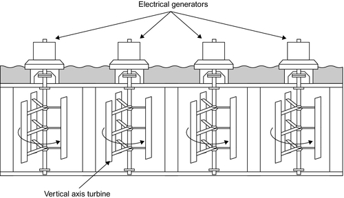
The insensitivity to flow direction means that a vertical-axis turbine will operate efficiently in a tidal region where the flow reverses twice a day. It will also be unaffected by cross-flows that might reduce the efficiency of a horizontal-axis turbine. Depending on the site this could prove a great advantage. Meanwhile, the ability to mount the generator at either end of the shaft means that it can be placed either on the seabed or riverbed or, more usefully, it can be deployed above sea level either from a shaft extending beyond the sea or on a floating support.
Vertical-axis turbines can come in a variety of shapes. One of the most popular from the early days of wind turbine development is the Darrieus or eggbeater design, so-called because its curved and twisted blades resemble the kitchen implement. Others have vertical blades mounted onto the shaft using horizontal struts to create an H-shaped rotor.
The H-shaped rotor has an additional advantage—it sweeps out a rectangular area as opposed to the circular sweep of a horizontal-axis turbine. This means the dimensions of the rotor can be tailored to the shape of the waterway into which it is to be sited. Arrays of vertical-axis turbines can, in principle, more efficiently collect energy from a water flow since they can be arranged to intersect a larger cross-sectional area.
Some vertical-axis turbines will have only two blades, others more. It is also possible to build a vertical-axis turbine with a rim generator. This type of machine, again, has no central axis. As a further variation, there is at least one design of vertical-axis machine that provides hydraulic power to the shore instead of incorporating a generator.
Cross-flow Turbines
A turbine that is like an old-fashioned water wheel can be used to generate power from all types of flowing water. Tidal mills from earlier centuries used this type of technology and modern versions can be adapted to a range of sites. This type of turbine is an efficient energy converter, but since only a part of it captures energy from the flowing water, it requires a larger turbine for the same power output as a fully submerged horizontal- or vertical-axis machine. The turbine has the additional disadvantage that it cannot operate on both the flow and ebb of a tidal site.
There is a variety of cross-flow turbines that will operate fully submerged. The turbine is similar to the anemometer used to measure wind speed. Blades are cup-shaped so that from one direction they capture the water but from the other they present a much lower water resistance. Though less efficient than more conventional types of turbines, these can be effective in small installations.
Other Marine Current Devices
In addition to the variety of turbines, there are other more unconventional marine current devices that have been developed and tested. One of these is based on a hydrofoil. A hydrofoil is a shaped blade that is intended to produce lift in exactly the same way as an airplane wing. To provide energy conversion, a section of hydrofoil is attached to the end of a beam, the opposite end of which is attached to a pivot. When this is placed in a flowing current with the hydrofoil horizontal, close to the bed of the river or sea, the flow of water will create lift, forcing it upwards and causing the pivoting beam to rise. However, when the angle of attack becomes too great, the hydrofoil instead generates drag and this forces the beam down again. See Figure 14.11.
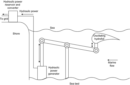
The oscillating motion will continue indefinitely so long as water continues to flow. The cyclic motion of the device can be used to drive a piston in and out of a cylinder and this can be used in a number of ways to produce electrical power. For example, it can be used to provide hydraulic pressure that can be utilized ashore, or it can be converted into rotary motion (just as in a piston engine) to drive a generator. The hydraulic version can also store energy in a hydraulic accumulator.
A variation on the basic hydrofoil design involves mounting the hydrofoil vertically at the end of the beam instead of horizontally. This generates an oscillatory motion from side to side, which can be exploited similarly to the vertical device.
The Venturi effect, found when a fluid is forced through a constricted opening, has also been exploited to generate power from marine flows. The Venturi effect is a pressure drop found within the fluid as it passes through the constriction, and in most cases this is used to enhance flow and increase efficiency of a turbine. However, one device uses the pressure drop to provide suction, generating an air flow that is used to drive a wind turbine.
Another novel system for generating power from marine flow proposes to utilize the magnetohydrodynamic effect, whereby an electric current is generated when a fluid that conducts electricity is passed through a powerful magnet. In a system put forward by Netherlands company Nepture Systems, salt water, which is an electrical conductor, is passed through a powerful magnetic field and electrical power is extracted. The system might be combined with a shoreline superconducting magnetic energy storage device that could both store energy from the generator and provide the powerful magnetic field needed for its operation.
Marine Current Projects
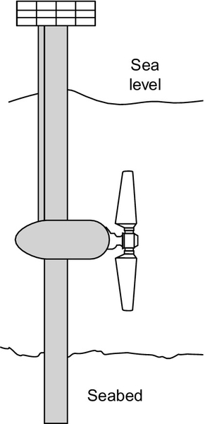
A number of marine current designs have reached the pilot stage of their development. One is Seagen, a device developed by U.K. company Marine Current Systems that now has Siemens as its major shareholder. The company has tested a pilot generator in Strangford lough in Northern Ireland. The demonstration unit comprised two 16 m horizontal-axis turbine trains, one mounted on each end of a horizontal beam that is attached to a vertical support. The power trains can be raised and lowered on the vertical support for maintenance. The pilot scheme had a generating capacity of 1200 kW. The company is now building a commercial 2 MW unit with two 20 m rotors.
Another U.K.-designed device is Deltastream, devised by Tidal Energy Ltd. This comprises a tripod structure that sits on the seabed with a turbine at each corner. Initial generating capacity is likely to be around 1 MW. The device is due to be tested in U.K. waters at the beginning of 2014. Meanwhile, Irish company OpenHydro has developed a shrouded turbine with a gravity base that it designed to sit on the seabed. This machine also has a rim generator and the turbine has a hole in its center to allow marine creatures to pass. The company has tested a 6 m pilot turbine.
In the United States, a company called UEK has developed the Underwater Electric Kite, essentially a device that comprises a pair of buoyant shrouded turbines, mounted together, tethered to the seabed and the whole structure flown like a kite in the flowing current. The design has been tested at a small scale but no major demonstration project appears to have been completed.
Vertical-axis turbines are the basis for Blue Energy Canada’s tidal fence concept. This involves deploying an array of vertical-axis turbines in a fence or barrage across a tidal estuary. A vertical-axis turbine is also the basis for Canadian company New Energy Corp.’s EnCurrent power generation system.
The Stingray is a hydrofoil-based oscillating generator. A 150 kW prototype was tested off the Scottish coast where it developed 40 kW in a 2 m/s current, but development appears to have halted.
Salinity gradient power generation
Salinity gradient power generation depends on the natural process of diffusion, or mixing. To understand how this can be used to generate electrical power, imagine a special box, divided into two compartments, as shown in Figure 14.12. One of the compartments is filled with salt water and the other with fresh water. If the division between the two compartments were carefully removed, without creating any turbulence, within a short period of time the water in both compartments would be salty. Diffusion would have mixed the fresh and salt water.
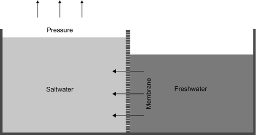
If the division between the two compartments is now replaced by a special, semi-permeable membrane that will allow water to pass through it but will not allow any dissolved salt to cross, when one side is filled with salt water from the sea and the other side with fresh water, water will pass through the membrane from the fresh side to the salt side to try and equalize the concentration of salt in each chamber. Since this is not possible, in theory the water will continue to cross until a head of water builds up on the salt side that can create a pressure sufficient to prevent further water crossing. For seawater, this equilibrium would require a head of 240 m.
Osmotic Power
The pressure that can be generated as a result of diffusion is clearly significant. In principle, it should be possible to exploit this pressure to generate electric power. This is the idea behind the osmotic power plant, first proposed by Sidney Loeb during the 1970s.
In an osmotic power plant a cell is created containing pressurized seawater and this is opened, through a semi-permeable membrane, to fresh water. Fresh water will then diffuse by osmosis into the pressurized chamber increasing the pressure further. The excess pressure is then released by allowing some of the salt water to flow out through a turbine.
The development of osmotic power has been taken up by the Norwegian utility Statkraft that built a prototype plant that began operating in 2009. The plant has a generating capacity of 2–4 kW, although the company predicts this can be raised to 10 kW with better-performing membranes.
Statkraft is proposing to build a much larger plant in Norway to demonstrate the principle. The proposed size is 1–2 MW. The company has estimated that the global potential for osmotic power generation is around 1600 TWh annually. Plants exploiting this technology would be sited at places where fresh water flows into the sea and would harness the mixing to generate electricity.
Vapor Compression
The vapor pressure of water that is generated above fresh water and salt water, if both are at the same temperature, is slightly different. Although the pressure difference is not great, it is possible to generate a vapor pressure from fresh water, under partial vacuum conditions, and then condense the vapor in salt water. This will create a pressure gradient that can be used to drive a gas turbine.
The pressure difference available is very small and would require a very large turbine, similar to an open cycle OTEC plant. This system does away with the need for a semi-permeable membrane but may be more difficult to develop than osmotic power.
Hydrocratic Power
If fresh water is introduced into the bottom of a vertical tube, pierced with holes, that is situated in salt water, then the salt water will force its way into the tube—driven by diffusion—to dilute the fresh water. The flow of water upwards through the tube is thus reinforced and a turbine placed in the flow can apparently generate more energy than is required to pump the fresh water into the pipe in the first place.
The process, christened hydrocratic power, has been patented and tests of its validity have been carried out. The scheme might be installed where power plant cooling water is discharged.
Reverse Electrodialysis
In principle, fresh and salt water can be used at two electrodes of a specially designed battery to produce an electric current directly. To achieve this, a series of cells are created with each separated from the next by a semi-permeable membrane. In this case, one membrane will only allow dissolved sodium ions to pass through it while the next will only allow dissolved chloride ions. Salt water is pumped into the first cell, fresh water into the second, salt water into the third, fresh water into the fourth, and so on along the line. Sodium ions will then diffuse from the salt water on one side into each fresh water cell, while chloride ions will diffuse from the other side. This will create a voltage separation between the saltwater cells on either side of the freshwater cell.
This process, called electrodialysis, was observed by R. Platte in 1954. The concept is the basis for the development of a power generation system by Netherland’s company REAPower.
Cost of marine power generation
All the marine power generation technologies in this chapter are at an early stage of development of commercialization and realistic installation costs are difficult to establish. Based on recent estimates, the most expensive is a floating OTEC plant that has an estimated cost between $4200/kW and $12,300/kW.1 Wave power plants are somewhat less expensive with an installation cost between $4100/kW and $6300/kW. Tidal stream plants have an estimated cost between $1700/kW and $4000/kW. Salinity gradient technologies are too new for any reliable estimates of installed cost to be available.
While all these technologies appear relatively expensive to install, the energy has no cost and so the electricity they produce should be somewhat cheaper than these installation costs indicate. Wave power–generated electricity appears to be the most expensive today with an estimated cost of more than $180/MWh. For OTEC, the cost estimates are $70–220/MWh and for tidal stream they are $40–120/MWh. Cost estimates for osmotic pressure power are $70–130/MWh.