
Coal-fired Power Plants
Abstract
Coal provides around 40% of the world’s electricity, more than any other source. Most modern coal-fired power stations burn pulverized coal in a boiler to raise steam for a steam turbine. High efficiency is achieved by using supercritical boilers made of advanced alloys that produce high steam temperatures, and large, high-efficiency steam turbines. Alternative types of coal-fired power plants include fluidized bed boilers that can burn a variety of poor fuels, as well as coal gasifiers that allow coal to be turned into a combustible gas that can be burned in a gas turbine. Emissions from coal plants include sulfur dioxide, nitrogen oxide, and trace metals, all of which must be controlled. Capturing carbon dioxide from a coal plant is also under consideration. This can be achieved using post-combustion capture, a pre-combustion gasification process, or by burning coal in oxygen instead of air.
Coal is the most important source of electrical power in the world today. At the end of the first decade of the 21st century it was responsible for over 40% of world electricity production, an annual output of around 8100 TWh out of a global total of 20,000 TWh in 2010, according to the U.S. Energy Information Administration.1
Significant deposits of coal can be found in most parts of the world, from the United States to South Africa, across Europe, many parts of Asia, and Australia. Exceptions exist, such as Japan and Taiwan, where resources are tiny; these countries, nevertheless, use large quantities of coal that they import. There are limited reserves in South America, and in Africa only South Africa has significant quantities while across the rest of that continent there is little.
The attractions of coal are that it is so widespread, it is often in plentiful supply, and where it is available it provides both a cost-effective and a secure source of electricity. It is for these reasons that many of the major economies across the world, including the two largest—the United States and China—have built their economic prosperity on coal.
Figures from the World Coal Association suggest that 45% of U.S. electricity is generated in coal-fired power plants, while in China the proportion is 79%. Table 3.1 lists the proportion of power derived from the fuel for these and the 10 other nations that rely most heavily on coal for electricity. The most reliant is South Africa, which derives 93% of all its electricity from coal, followed closely by Poland with 90%. India is high up the list with 69%, while Germany, last on the list, derives 44% of its electrical power from coal. Many of these countries have their own reserves but some, such as Morocco, import the fuel.
Table 3.1
Coal-fired Power Generation for Leading Coal-using Countries*
| Country | Proportion of Electricity Derived from Coal |
| South Africa | 93% |
| Poland | 90% |
| China | 79% |
| Australia | 76% |
| Kazakhstan | 70% |
| India | 69% |
| Israel | 63% |
| Czech Republic | 56% |
| Morocco | 55% |
| Greece | 55% |
| United States | 45% |
| Germany | 44% |
Source: World Coal Association.
* These data are for 2008–2009.
Alongside availability, the cost of coal is another important factor in its dominance. Coal prices have traditionally been stable and low compared to alternative fossil fuels, with coal typically half the cost of natural gas on an energy content basis. In recent years the price of the fuel has shown greater volatility than in the past, as has the price of many other globally traded commodities. Nevertheless, the cost is still low enough to make it an attractive source of electricity in many parts of the world.
On the other hand, coal has a lower energy density than other fossil fuels (Table 3.2) and is consequently more expensive to transport. When it is transported, it is usually by road over short distances; by rail, river, or canal over longer distances; and by ship when traded intercontinentally. Pipeline transportation, common with both oil and gas, cannot be used for coal. Therefore, coal is most economically utilized close to its source.
Table 3.2
Energy Densities for Different Fossil Fuels
| Fossil Fuel | Average Energy Density |
| Coal | 24 MJ/kg |
| Crude oil | 46 MJ/kg |
| Natural gas | 54 MJ/kg |
The major disadvantage of coal is that it is the dirtiest of the fossil fuels. Many coals contain significant amounts of sulfur, which when burned generates sulfur dioxide (SO2). They can also contain numerous trace elements including heavy metals such as mercury, which are released when the fuel is burned and can find their way into the environment. Coal combustion, like all other types of fossil fuel combustion, generates nitrogen oxide (NOx), which is damaging if released into the atmosphere, and the combustion process also releases large quantities of dust. On top of this, coal combustion generates more carbon dioxide (CO2) for each unit of energy produced than any other fossil fuel.
In spite of all these potential pollutants associated with its combustion, for most of its history as a source of electricity energy, coal combustion has not been controlled. As a consequence it has been one of the most widespread and damaging forms of human industrial activity, generating high levels of pollution in many parts of the world. Coal combustion is now much more tightly regulated than in the past, and extensive emission control systems are required for new coal-fired power stations built virtually anywhere. This has made coal-fired power generation less cost effective than in the past, but it still remains competitive with other major sources of electrical energy.
Types of coal
The term coal embraces a range of materials. Within this range there are a number of distinct types of coal, each with different physical properties. These properties affect the suitability of the coal for power generation.
The hardest of coals is anthracite. This coal contains the highest percentage of carbon (up to 98%) and very little volatile matter or moisture. When burned it produces little ash and relatively low levels of pollution. Its energy density is generally higher than other coals at 23 MJ/kg to 33 MJ/kg. Anthracite is typically slow-burning and often difficult to fire in a power station boiler unless it is mixed with another fuel. While its energy content makes it attractive as a power plant fuel, the difficulty with firing it and its cost does not, so it has traditionally been used for heating rather than industrial use. However, it is becoming more common as a power plant fuel as countries with large reserves, such as Russia and Ukraine, switch to anthracite to free natural gas for export.
While anthracite reserves are important, the most abundant of the coals are the bituminous coals. These coals contain significant amounts of volatile matter. When they are heated they form a sticky mass, from which their name is derived. Bituminous coals normally contain between 45% and 70% carbon. Moisture content is between 5% and 10%. They burn easily, especially when ground or pulverized. This makes them ideal fuels for power stations. Bituminous coals are further characterized, depending on the amount of volatile matter they contain, as high-, medium-, or low-volatile bituminous coals. Some bituminous coals contain high levels of sulfur, which can be a handicap for power generation purposes.
A third category, called sub-bituminous coals or soft coals, are black or black-brown. These coals contain between 35% and 45% carbon and 15% to 30% water, even though they appear dry. They burn well, making them suitable as power plant fuels, and sulfur content is low.
The last group of coals that are widely used in power stations are lignites. These are brown rather than black and have a carbon content of 20–35%. Moisture content is 30–50%. Lignites are formed from plants that are rich in resins and contain a significant amount of volatile material. The amount of water in lignites, and their consequent low carbon content, makes the fuel uneconomic to transport over any great distance. Lignite-fired power stations are usually found adjacent to the source of fuel.
A type of unconsolidated lignite, usually found close to the surface of the Earth where it can be strip-mined, is sometimes called brown coal. (This name is common in Germany.) Brown coal has a moisture content around 45%. Peat is also burned in power plants, though rarely.
Coal reserves
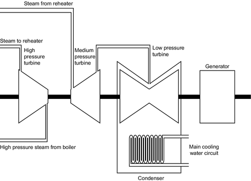
Table 3.3 shows the global proven coal reserves, which at the end of 2010 amounted to 860,938 Mtonnes. The greatest reserves are in Europe and Eurasia with 304,604 Mtonnes, followed by the Asia-Pacific region with 265,843 Mtonnes and North America with 245,088 Mtonnes. Reserves in the Middle East and Africa are small by comparison at 32,895 Mtonnes, and those in Central and South America even smaller at 12,508 Mtonnes.
Table 3.3
Proven Coal Reserves at the End of 2010
| Region | Anthracite and Bituminous (Mtonnes) | Sub-bituminous and Lignites (Mtonnes) | Total (Mtonnes) | Reserve/Production Ratio |
| North America | 112,835 | 132,253 | 245,088 | 228 |
| Central and South America | 6890 | 5618 | 12,508 | 124 |
| Europe and Eurasia | 92,990 | 211,614 | 304,604 | 242 |
| Middle East and Africa | 32,721 | 174 | 32,895 | 126 |
| Asia-Pacific | 159,329 | 106,512 | 265,843 | 53 |
| Total | 404,762 | 456,176 | 860,938 | 112 |
Source: BP Statistical Review of World Energy.
When these are subdivided into types as shown in the table, Europe’s reserves can be seen to be composed primarily of lower-quality sub-bituminous coals and lignite. North America has relatively higher quantities of the high-quality coals but the greatest reserves of these are in the Asia-Pacific region.
While coal is generally considered to be widely available, five countries hold 75% of all proven coal reserves: United States USA (28%), Russia (18%), China (13%), Australia (9%), and India (7%). At the current rate of consumption the world’s proven coal reserves would last for another 112 years, as shown in Table 3.3. However, this varies from region to region with European and Eurasian reserves likely to persist the longest, while those in the Asia-Pacific region might only last for a further 57 years if current production rates continue. However, in all regions proven reserves represent only a portion of the coal that actually lies in the ground, and these potential reserves are likely to be much higher than those shown in Table 3.3.
The leading coal-producing nation is China, which mined 3520 Mtonnes of hard coal in 2011. The United States, the second largest producer, mined only 993 Mtonnes, and India 589 Mtonnes. Other important coal-producing countries include Australia (416 Mtonnes in 2011), Indonesia (325 Mtonnes), South Africa (255 Mtonnes), and Russia (334 Mtonnes). The main European coal producers are Germany (189 Mtonnes) and Poland (139 Mtonnes). According to the World Coal Association most coal is consumed in the country of origin and only around 16% is traded internationally. However, this represents an important source of energy for countries, such as Japan, South Korea, and Taiwan, which have virtually no reserves of their own. China, in spite of its massive coal production, is also a net importer of coal. Meanwhile, the major exporting nations are Australia, Indonesia, and Russia.
The cost of transporting coal means that trade routes are normally kept as short as possible. So, for example, Australian and Indonesian coal is most often sold to other Asia-Pacific countries, such as Japan, South Korea, and China. Russia and South Africa, another important coal-exporting nation, trade mostly with Europe, while U.S. coal exports to other countries in the Americas.
Coal cleaning and processing
Coal cleaning offers a way of improving the quality of a coal, both economically and environmentally. The most well-established methods of coal cleaning focus on removing excess moisture from the coal and reducing the amount of incombustible material, which will remain as ash after combustion. Moisture removal reduces the weight and volume of the coal, rendering it more economical to transport and easier to burn. Ash removal improves its combustion properties and aids power plant performance.
Moisture is removed from coal by drying. This can simply be solar drying—leaving the coal in the open before transporting it. Drying coal in this way can reduce its mass and increase its energy density, making it relatively cheaper to transport.
The alternative—drying coal by heating—is most often carried out at the power station, utilizing waste heat in the plant flue gases. Such a procedure is absolutely essential when burning high-moisture lignites such as brown coal. In this case, drying does not affect transportation costs because the fuel has, by this stage, already reached the power station.
Ash removal is carried out by crushing the coal into small particles. Incombustible mineral particles are more dense than the coal and can be separated using a gravity-based method. Such treatment will remove some minerals containing sulfur, and can result in a reduction of up to 40% in sulfur dioxide emissions during combustion. (Some sulfur is bound to the carbon in the coal; such sulfur is not affected by this type of cleaning.)
There have been attempts to develop more advanced methods for coal treatment employing either higher-temperature processing of the coal or chemical rather than physical processes. These processes, which are aimed at removing polluting impurities in the coal to make it a cleaner fuel to burn, have not so far found commercial application. Coal-cleaning processes are also being developed to treat coal wastes that have previously been discarded to make them suitable for combustion.
Traditional coal-fired power generation technology
The traditional method of producing electricity from coal is to burn the fuel in air and capture the heat released during the combustion in a boiler where it is used to raise steam, the latter driving a steam turbine generator. This type of power plant has been evolving since the modern steam turbine was invented by Charles Parsons in 1884. His first unit drove a dynamo that produced 7.5 kW of electrical power.
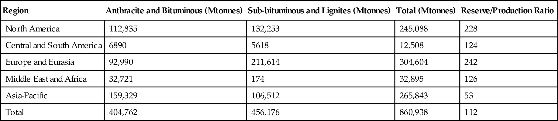
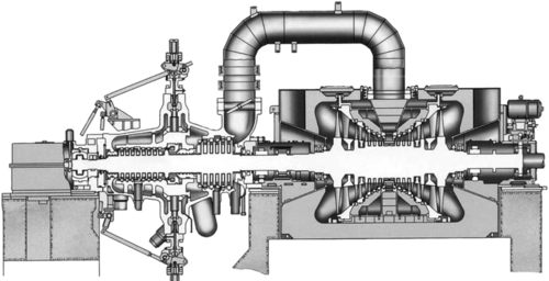
A power plant of this type is made up of several key components (Figure 3.1). There will be a fuel handling system designed to receive the bulk coal deliveries from the mine and convert the mined coal into a form that can be readily burned. In most modern coal-fired power plants this involves crushing the fuel to produce a powder. This pulverized coal is then fed into a combustion system where it is mixed with air and ignited under controlled conditions, releasing chemical energy as heat. This heat is captured by water within tubes in the boiler, the heat energy converting the water into steam. The combustion system and boiler must be closely integrated for highest efficiency and will normally be considered a single unit in modern plants. Once combustion is complete most of the ash residue falls to the bottom of the combustion chamber and is removed as slag. However, some ash forms into fine particles that are carried away with the hot combustion gases. These particles must be removed at a later stage.
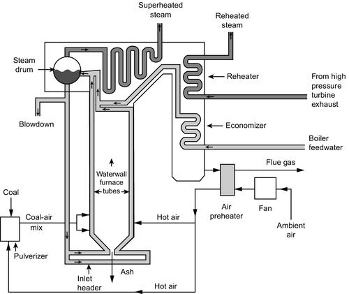
Steam generated in the boiler is carried to a steam turbine that is designed to extract as much heat energy as possible from the gas. In a large coal-fired power station the steam turbine is likely to be composed of at least three elements: a high-pressure (HP) turbine, an intermediate-pressure (IP) turbine, and one or more low-pressure (LP) turbines. Steam passes from one to the next in sequence. Higher efficiency can often be achieved by reheating the steam between the HP and IP turbines by returning it through a special stage of the boiler called a reheater.
To extract the maximum amount of energy from the steam, a condenser is fitted to the output of the LP turbine(s) to condense the steam back into water. The colder the cooling water used in the condenser, the higher the efficiency will be. The water is then returned to the boiler and passes around the cycle again.
The hot flue gases that exit the combustion chamber of the plant and pass through the boiler are rich in carbon dioxide and laden with impurities. These impurities include sulfur dioxide, nitrogen oxide, heavy metals, organic compounds, and tiny ash particles. All these impurities must be removed before the flue gas can be released into the atmosphere. Cleaning is carried out in a sequence of flue-gas cleaning systems, each a separate chemical or filtration plant. Carbon dioxide in not currently removed from commercial coal-fired power plants, but technology for its capture is advanced and is expected to be deployed within a decade. A plant that applies all these processes, including carbon dioxide capture, may be called a zero-emission plant, although in fact, traces of all will still be released.
Efficiency is the key to modern coal-burning technology. The higher the ratio of electrical energy output to chemical energy input of the coal combustion process, the cheaper each unit of electricity produced will be. For modern plants without carbon dioxide capture, higher efficiency also means lower emissions per unit of electricity produced.
Of the chemical energy contained with the coal, around 15% is lost to the energy conversion system. The remainder is utilized to heat steam so that the hot steam contains around 85% of the original chemical energy. Converting the hot steam into electricity relies on the Carnot thermodynamic cycle. Conversion efficiency depends on the temperature and pressure of the steam (more accurately the temperature and pressure drop that is achieved between steam turbine inlet and outlet), so the development of coal-fired power plant technology is directed at producing steam at the highest temperature and pressure possible. From an energy viewpoint, therefore, the two most important components of a coal-fired power station are the boiler, which produces high-temperature, high-pressure steam, and the steam turbine, which must then convert the energy carried by that steam into electrical energy.
Boiler technology
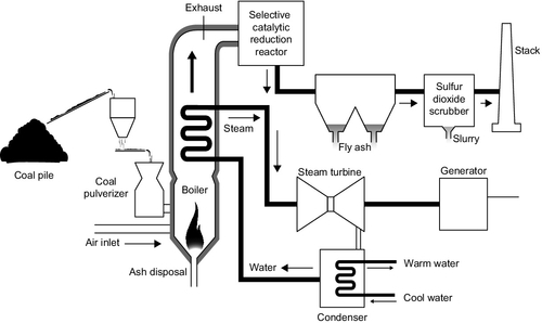
The boiler in a coal-fired power plant converts chemical energy contained within the coal into heat energy that is captured and carried away in hot, high-pressure steam (Figure 3.2). Coal-burning technology has a long history and has seen many plant configurations, but the most important type of plant in modern use is the pulverized coal-fired power plant, often abbreviated as PC plant. PC plants probably account for more than 90% of all operating coal-fired power stations in general use and this type of plant is the main plant design for future high-efficiency coal-fired plants.
A PC plant burns coal that has first been ground to a fine powder using large grinding mills. A typical plant will have several of these, each feeding a single burner. These burners are where the coal, mixed with air, is injected into the boiler where it ignites in a high-temperature fireball inside the furnace, consuming the fuel and releasing chemical energy as heat.2 Several burners are used to create a stable fireball in the center of the furnace where combustion takes place. The temperature within the fireball may reach 1500–1700 °C in the hottest part of the flame. At these temperatures the nitrogen in air is easily oxidized to produce nitrogen oxide. To keep nitrogen oxide production at a minimum, the amount of air entering the combustion chamber with the pulverized coal is restricted, maintaining a chemically reducing atmosphere in which virtually all the oxygen is captured during carbon combustion, leaving none to react with nitrogen. Additional air is then introduced higher up the combustion chamber to complete the coal combustion process, at a point where the temperature of the combustion gases has lowered and the reaction of oxygen with nitrogen proceeds more slowly.
The heat released during combustion is partly radiant heat and partly convective heat. Radiant heat is captured by water running in tubes within the walls of the combustion chamber. Further collections of tubes are placed in the path of the flue gases exiting the combustion chamber, and as water passes from one set of tubes to another its temperature rises and finally steam is generated (Figure 3.3). In a conventional boiler this will take place within a steam drum, which allows the phase change between liquid and gas to proceed smoothly. Steam from the drum may then be superheated to create an even higher-temperature gas.

In the most modern plants the temperature and pressure within the boiler tubes is such that water enters a supercritical state under which the distinction between liquid and gaseous states cease to exist. With this type of plant a steam drum is not necessary. Units of this sort are called supercritical boilers, while those with steam drums are called subcritical boilers. Supercritical boilers are capable of producing steam at much higher temperatures and pressures than subcritical boilers, therefore steam turbines fed from such plants are capable of higher Carnot cycle efficiency.
The supercritical point for water occurs at 22.1 MPa/374.1 °C. So long water remains above the supercritical point and within its supercritical phase there is no longer a need for a drum in a power plant steam system to allow the water to boil. Instead the conversion from water to steam can occur homogenously within the boiler pipes as the temperature rises.
Steam conditions at the exit of a modern subcritical power plant boiler vary widely but typical figures would be a steam temperature of 540 °C and a steam pressure of 17.5 MPa. Such a plant would be capable of generating power at an efficiency of around 38%, depending on site conditions. Supercritical power plants operate at steam exit temperatures of 540–600 °C and at exit pressures of 23–30 MPa. These plants can achieve efficiencies up to 41%. There is a further subdivision called ultra-supercritical power plants that operate at even higher temperatures and pressures. Although the definition of ultra-supercritical is not precise,3 plants operating at these more extreme conditions have been capable of up to 45% efficiency under optimum site conditions. In comparison, the average efficiency of coal-fired plants operating across the globe is around 28% and that of the U.S. coal fleet is around 33%.
The extreme temperatures and pressures in supercritical boilers make extreme demands on the materials used to construct them. While steam boilers have traditionally been constructed from steels, conditions in ultra-supercritical power plants require that some components are made from nickel-based alloys similar to those used to construct the high-temperature components used in gas turbines. These materials are more costly than steels. With further materials development it is expected that future plants will be able to operate at steam temperatures of 700–750 °C. This should permit an energy-to-electrical conversion efficiency as high as 55% to be achieved in a coal-fired steam plant.
While efficiency is the most important factor driving boiler design, flexibility has also been recognized as vital in recent years. Coal-fired power plants have traditionally operated as base-load power stations operating essentially at full output all the time. This is no longer the situation everywhere. In some regions coal-fired power stations are being used to support the generation of renewable electricity. This means they have to be able to operate both efficiently and effectively at part load as well as full load, and to be able to change output load as required by the grid. One technique being used to achieve this is sliding-pressure operation under which the steam pressure is allowed to fall as output falls but steam temperature is maintained. With sliding-load operation it is possible to maintain relatively high efficiency at part load, even though this may involve falling below the critical point of water.
Steam turbine design
The steam turbine is the primary mechanical device (sometimes called the prime mover) in most conventional coal-fired power stations. Its job is to convert the heat energy contained in the steam exiting the boiler into mechanical energy, rotary motion. The steam turbine first appeared in power applications at the end of the 19th century. Before that steam power was derived from steam-driven piston engines.
The steam turbine is something of a cross between a hydropower turbine and a windmill (Figures 3.4 and 3.5). It, like them, is designed to extract energy from a moving fluid and the fluid it exploits is a form of water, the same as the hydroturbine. In the case of a hydroturbine the water remains in the liquid phase and neither its volume nor its temperature changes during energy extraction. In the case of the steam turbine, energy extraction is from a gas (steam) rather than a liquid and involves both the pressure and temperature of the fluid falling. This has a profound effect on the turbine design.
Both hydroturbines and steam turbines exist in two broad types: impulse turbines that extract the energy from a fast-moving jet of fluid, and reaction turbines that are designed to exploit the pressure of a fluid rather than its motion. A hydroturbine will be of one design or the other. In a steam turbine the two principles may be mixed in a single machine and they may even be mixed in a single turbine blade.
It is impossible to extract all the energy from steam using a turbine with a single set of turbine blades. Instead, a steam turbine utilizes a series of sets of blades, called stages. Each stage is followed by a set of stationary blades (usually called nozzles) that control the steam flow to the next stage.
A single steam turbine stage consists of a set of narrow blades projecting from a central hub. (In concept, it is something like a steam windmill.) Ten or more sets of blades can be mounted on a single steam turbine shaft. This combination of shaft and blades is called a rotor. The turbine stages are separated by carefully designed stationary blades, or nozzles, that control the flow of steam from one set of rotating blades to the next. The precise shape of the blades in each set determines whether that set is impulse or reaction, or a cross between the two. The hub, blades, and nozzles are enclosed in a close-fitting case to maintain the steam pressure.
In a steam turbine impulse stage, energy is extracted at constant pressure while the velocity of the steam falls as it flows across the blades. The steam is then expanded through a stationary control stage to increase its velocity again before energy is extracted from another set of impulse blades. In a steam turbine reaction stage, by contrast, both pressure and velocity of the steam fall as energy is extracted by the rotating blades.
Steam exiting the power plant boiler is at a high temperature and pressure. Both temperature and pressure fall as the steam passes through the turbine. The greater the temperature drop and the greater the pressure drop available, the more energy can potentially be captured from the steam. Consequently, the most efficient power plants condense the steam back to water at the end of the turbine.
Even with a modern design it is impossible to capture all the energy from the steam efficiently with a single multiple-stage turbine. Coal-fired power plants use several, designated HP, IP, and LP turbines. The blades in these turbines get larger (longer) as the pressure drops; in fact, the LP turbine may comprise several turbines operating in parallel to extract the last energy from the steam because a single turbine designed to achieve the same energy extraction would be impossibly large. All the turbines may be mounted on a single shaft, but it is common for the LP turbines to be on a separate shaft rotating at a lower speed to reduce the forces exerted as the blade tips. Multiple turbines of this type can have aggregate outputs over 1000 MW.
As with boilers, the demands of modern power plant design have led to the development and introduction of high-performance materials that can cope with the extreme conditions encountered within a steam turbine. The high-pressure turbine blades have to be able to withstand extremes of both temperature and pressure and to resist the abrasive force of steam. At the low-pressure end of the turbine train the large size of the turbines means that the blade tip speeds are enormous, again requiring specially designed materials to withstand the centrifugal forces exerted on them.
A refinement that improves the overall efficiency in a steam plant is to return the steam to the boiler after it has passed through the HP turbine, reheating it before delivering it to the IP turbine. Most modern steam turbine plants use this single reheat design (multiple reheat is also possible).
The theoretical maximum efficiency of a coal-fired power station is determined by the temperature difference between the steam entering the HP turbine and the temperature exiting the LP turbine. The greater this temperature difference, the more energy can be extracted. With the most advanced technology, utilizing the best boiler materials to achieve the highest steam temperatures and pressures and with optimum site conditions, a maximum efficiency of 43–45% can be achieved. New supercritical designs may eventually push this as high as 55%. In the near future, however, the best that is likely to be achieved is something between 47% and 49%.
Generators
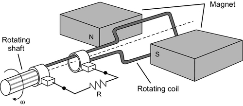
The turbine shaft, or shafts if there are more than one, are coupled to a generator that converts the rotary mechanical motion into the electrical energy that the plant is designed to produce. Generators, like steam turbines, first appeared during the 19th century. All utilize a coil of a conducting material, usually copper, moving in a magnetic field to generate electricity, as shown in Figure 3.6.
The generators used in most power stations, including coal-fired power stations, are designed to deliver an alternating current (AC) to a power grid. An AC current is preferred because it allows the voltage to be raised or lowered easily using a transformer. For transmission of power over long distances it is preferable to use a very high voltage and a low current. The voltage is then reduced with a transformer before delivery to the consumer.
The need to generate an AC voltage determines the speed at which the generator rotates. This must be an exact multiple of the grid frequency (normally grids operate at either 50 Hz or 60 Hz). For grids operating at 50 Hz the traditional generator speed is 50 cycles per second, or 3000 rpm for a standard two-pole generator, or half this speed, 1500 rpm, for a four-pole generator. The equivalent 60 Hz two-pole machine rotates at 3600 rpm and a four-pole machine at 1800 rpm. This speed, in turn, determines the operating speed of the steam turbine. Large LP steam turbines may operate at the lower speeds to reduce stress on the long turbine blades.
Generators may be as large as 2000 MW, and large generators are normally designed for the specific project in which they will operate. Modern generators operate with an efficiency of greater than 95%. The remaining 5% of the mechanical input energy from the turbine is usually lost as heat within the generator windings and magnetic components. Even though the percentage is small, this still represents an enormous amount of energy, perhaps 50 MW in a 1000 MW machine. Therefore, generators require very efficient cooling systems to prevent them from overheating. For smaller generators up to around 300 MW, air cooling will normally be sufficient. Larger generators, up to 500 MW, usually use hydrogen cooling. Above this size, the rotating section of the generator, the rotor, will normally be hydrogen cooled while the stationary part, the stator, will be water cooled through pipes embedded into its structure.
The broad outline of generator design has changed little over a century. However, new materials have improved efficiencies. The latest developments involve the use of superconducting materials to reduce energy loss and increase efficiencies. These have yet to achieve commercial viability.
Fluidized bed combustion
While the pulverized coal-fired boiler represents the most efficient type of coal-fired power plant, there are alternatives. One of these is the fluidized bed boiler. This type of combustion system is capable of burning a much wider range of fuels than a PC plant. It operates at a lower temperature, making the production of nitrogen oxide less of a problem, and it can also incorporate sulfur capture within the combustion chamber, leading in principle at least to easier emission control.
The concept behind the fluidized bed is simple: to create a solid-state reactor that mimics liquid-phase reactors. If a layer of sand, finely ground coal, or another fine solid material is placed in a container and high-pressure air is blown through it from below, the particles, provided they are small enough, become entrained in the air and form a floating (i.e., fluidized) bed of solid particles above the bottom of the container. This bed of solid particles now behaves like a liquid in which the constituent particles constantly move to and from and collide with one another like the molecules in a liquid. As a type of reactor, this offers some significant advantages because it encourages much more rapid and thorough reaction between the particles within the bed or between the particles and air in the case of combustion.
The fluidized bed was used first in the process industries to enhance the efficiency of chemical reactions between solids by simulating conditions of a liquid-phase reaction and as a simple method of reducing emissions from industrial plants. Only later was its application for power generation recognized. Its use is now widespread. The fluidized bed can burn a variety of coals and other poorer fuels, such as peat, coal-cleaning waste, petroleum coke, wood, and other biomass. See Figure 3.7 for a diagram of its circulation.
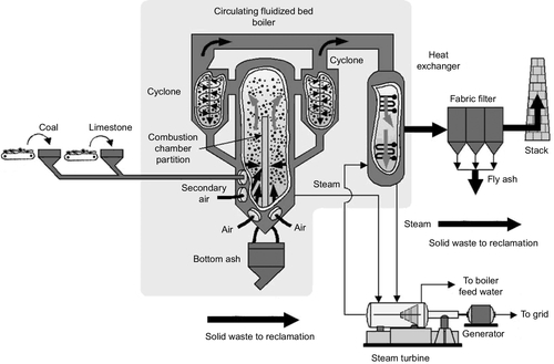
A fluidized bed used for power generation contains only around 5% coal or fuel within the actual bed. The remainder of the bed is primarily an inert material, such as ash or sand. The temperature in a fluidized bed is around 950 °C, significantly lower than the temperature in the heart of a pulverized coal furnace. This low temperature helps minimize the production of nitrogen oxide. A reactant such as limestone can also be added to the bed to capture sulfur, reducing the amount of sulfur dioxide released into the exhaust gas. One further advantage of the fluidized bed is that boiler pipes can be immersed in the bed itself, allowing extremely efficient heat capture (but also exposing the pipes to potentially high levels of erosion).
There are three primary designs for fluidized bed power plants in use. The simplest, called a bubbling bed plant, is essentially a conventional boiler in which the combustion chamber has been replaced with a fluidized bed. Air is blown at relatively low velocity into the chamber from beneath the bed to maintain its fluid state and fuel introduced from above. Ash is removed from below, as in a PC plant, and additional, overfire air is blown in above the bed to complete the combustion process. Bubbling fluidized bed plants are often used in biomass plants.
The second, more complex design is the circulating fluidized bed plant. In this type of fluidized bed the particles are fluidized at high speed by using high-velocity air and a cycling fluidized mass is created. The high-speed particles within this type of plant pass up out of the combustion chamber and are then recovered and recirculated by passing the flow of flue gases and particles through a cyclone filter that returns the particles to the bed while allowing the flue gases to flow onwards. Such plants provide good mixing and long residence times for particles so that emission control using additives in the bed can be more effective. They are also capable of burning higher calorific value fuels such as anthracite, which would be more difficult to combust completely in the bubbling bed reactor.
The circulating bed can remove 90–95% of the sulfur from the coal while the bubbling bed can achieve between 70% and 90% removal. Maximum energy conversion efficiency is 43%, similar to that of a traditional pulverized coal plant. However, such high efficiencies can only be achieved with larger plants that can employ larger, and generally more efficient, steam turbines under optimum steam conditions. Advanced fluidized bed plants are built with supercritical boilers to achieve these high conversion efficiencies.
A third type of fluidized bed design, called the pressurized fluidized bed (Figure 3.8), was developed in the late 1980s and the first demonstration plants employing this technology were constructed in the mid-1990s. The pressurized bed is like a bubbling bed, but operates at a pressure between 5 atmospheres and 20 atmospheres. This allows higher overall efficiency to be achieved.
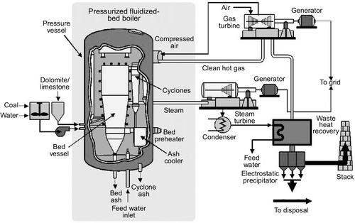
Operation under high pressure means that the flue gases exiting the boiler can be passed through a gas turbine to capture additional energy for power generation. This is in addition to the power generated by the traditional steam cycle. In principle, a pressurized fluidized bed power plant is capable of a conversion efficiency of 44–45%, but in practice they have not achieved this level. The largest pressurized fluidized bed power plant in operation is a 360 MW unit in Japan. This plant, with a supercritical boiler, has a claimed efficiency of 42%.
Although commercial fluidized bed power plants with capacities of over 400 MW are available, the units have not proved as efficient as supercritical PC power plants for coal combustion. Their sulfur and nitrogen oxide emissions, though lower than from an unmitigated PC power plant, are often too high to meet statutory regulations and additional measures are required to control the emissions. However, the plants can burn a variety of fuels other than coal. This has made them attractive for a range of projects where low-grade fuels, fuel waste, or biomass are to be burned.
Integrated gasification combined cycle
A second alternative to the pulverized coal-fired power plant is the integrated gasification combined cycle (IGCC) plant that is based around the gasification of coal (Figure 3.9). Coal gasification is an old technology. It was widely used to produce town gas for industrial and domestic use in the United States and Europe until natural gas became readily available.
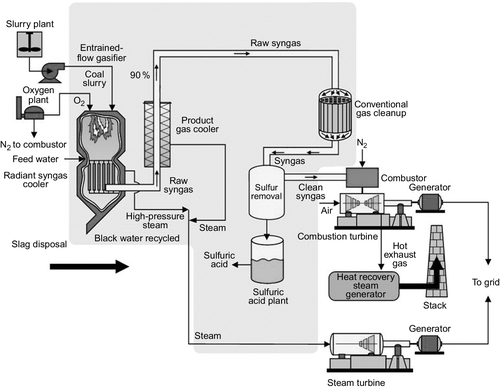
Modern gasifiers convert coal into a mixture of hydrogen (H) and carbon monoxide (CO), both of which are combustible. Gasification normally takes place by heating the coal with a mixture of steam and oxygen (or, in some cases, air). This can be carried out in a variety of gasifier designs including fixed bed, fluidized bed, and entrained flow gasifiers. The primary reaction for combustible gas production is that of the carbon in coal with water to produce hydrogen and carbon monoxide:
![]()
However, there are other reactions that produce carbon dioxide and methane or other hydrocarbons. Both hydrogen and carbon monoxide are combustible.
The process that takes place in the gasifier is a partial combustion of the coal. Consequently, it generates a considerable amount of heat. This heat can be used to generate steam to drive a steam turbine. The gas produced, meanwhile, is cleaned and can be burned in a gas turbine to produce further electricity. Heat from the exhaust of the gas turbine is used to raise additional steam for power generation. This is the basis of the IGCC plant although a variety of configurations exist.
There are a limited number of IGCC plants in operation with capacities of 250–300 MW. They have demonstrated efficiencies of 40%. However, capital costs are higher than for pulverized coal-fired power plants. Costs might improve if hot-gas cleanup technologies can be developed, but current IGCC technology does not offer a viable alternative to a supercritical PC plant under most conditions. However, IGCC might offer an effective means of carbon capture in a coal-fired power plant (see the following section) and this may prove its greatest opportunity for the future.
Emission control for coal-fired power plants
The combustion of coal is the dirtiest of the large-scale methods of generating electricity, primarily because of the range of pollutants that are found within the fuel. Most coals contain some sulfur. Often it is more than 3% of the coal and it may reach as much as 10%. When the coal is burned this sulfur is converted into sulfur dioxide and carried off by the flue gases. If released into the atmosphere it can be converted into an acid with potent consequences. There is a small amount of organic nitrogen with coal too. During combustion this is converted into nitrogen oxides of various sorts. However, the main source of these gaseous nitrogen compounds is the nitrogen in air that can become oxidized at the high temperatures encountered within coal furnaces. These two can be potent pollutants.
Coal usually contains a significant amount of mineral impurity too. A large part of this fuses to create solid lumps, which are left behind in the combustion chamber as slag. However, some are reduced to tiny solid particles that get carried away with the flue gas. The particles may contain heavy metals, such as cadmium and mercury, that, if allowed to escape, will be released into the environment. Some coals, particularly the bituminous varieties, contain large amounts of volatile organic compounds and these, or fragments of them generated by their incomplete combustion, can also be released. Incomplete combustion of the carbon in coal may also lead to significant levels of carbon monoxide within the flue gases.
Environmental regulations require that as far as possible these materials are removed from coal-fired power plant flue gases before the latter are released into the atmosphere. Different techniques have been developed for the most important of these: sulfur scrubbers for removing sulfur compounds, low nitrogen oxide burners and catalytic reduction systems to remove nitrogen oxide, and filters and electrostatic precipitators to control dust emissions. Other trace elements such as heavy metals may require their own removal plants but often these can be tackled alongside one or the other pollutants, making an additional chemical treatment process unnecessary.
Table 3.4 contains figures for the concentrations of various power plant airborne pollutants that are considered permissible in the EU and United States if good air quality is to be maintained. EU regulations are generally stricter; for example, the EU expects sulfur dioxide concentrations over a 24-hour period to be below 125 μg/m3. In the United States the same standard is 365 μg/m3. However, internationally, standards are tending to converge as the effects of even low levels of pollution on human health become more widely recognized. The PM10 particulate matter standard is for dust particles greater than 10 μm in diameter; this is generally the standard of importance when considering dust from coal-fired power plants. There are other standards including PM2.5 for particles up to 2.5 μm in diameter.
Table 3.4
Air-quality Standards
| Pollutant | EU Standard | U.S. Standard |
| Sulfur dioxide | 125 μg/m3 | 365 μg/m3 |
| Nitrogen oxide | 40 μg/m3 | 100 μg/m3 |
| Particulate matter (PM10) | 40 μg/m3 | 150 μg/m3 |
| Carbon monoxide | 10 mg/m3 | 10 mg/m3 |
| Ozone | 120 μg/m3 | 150 μg/m3 |
Source: EU Commission and U.S. Environmental Protection Agency.
The figures in Table 3.4 apply to the air quality that people will encounter in the street or in their houses or offices when carrying out their daily lives. The actual emissions permitted by power plants are generally much higher than this. A power plant represents a concentrated source of pollutants, but these are released in hot gases from a tall stack so that they should rise high into the atmosphere and become diluted before humans or other life-forms come into contact with them. However, the behavior of the pollutants once they enter the atmosphere is not always predictable. The behavior of the plume of exhaust gases from a power plant stack will depend on atmospheric conditions, so sometimes the pollutants will fall close around the plant and at other times they may be carried across continents.
Table 3.5 shows some of the emission levels permitted within the EU for power plant flue gases. The figures are for large plants with a thermal capacity in excess of 300 MW. The limits are less strict for some smaller plants. For sulfur dioxide the limit for plants built after 2003 is 200 mg/m3, falling to 150 mg/m3 after 2016. Permitted emission levels for nitrogen oxide are the same. Dust emissions are to be below 20 mg/m3 after 2016 and there is a proposed emission limit for mercury of 30 μg/m3. As earlier, these EU limits are probably some of the strictest to be found, but as with air-quality standards, the regulations are becoming stricter everywhere.
Table 3.5
EU Emission Limits for Large Power Plants
| Sulfur dioxide emissions for plants built after 2003 | 200 mg/m3 |
| Sulfur dioxide emission limits after 2016 | 150 mg/m3 |
| Nitrogen oxide emissions for plants built after 2003 | 200 mg/m3 |
| Nitrogen oxide emission limits after 2016 | 150 mg/m3 |
| Dust emission limits after 2016 | 20 mg/m3 |
| Proposed mercury emission limit | 30 μg/m3 |
Source: EU Commission.
There is one other important combustion product of coal combustion not included in the preceding tables or discussion: carbon dioxide. This is the reaction product when carbon is burned in air, the reaction of which releases the heat energy used to generate electricity. The flue gases from the boiler of a typical advanced coal-fired power plant may contain up to 14% carbon dioxide depending on the specific plant conditions.
The release of carbon dioxide from the combustion of fossil fuels in power plants and elsewhere into the atmosphere is widely regarded as the main cause for a steady but accelerating rise in average global temperatures over the past 150 years. This is seen as potentially damaging to the global environment. The capture and removal of carbon dioxide from fossil fuel power plant flue gases is not yet mandatory anywhere, but measures to try and control its emissions are being introduced in some parts of the world, particularly the EU. At the same time, methods for capturing the gas are being developed and there is a growing consensus that these will need to be deployed on a commercial scale after 2020 if global warming is to be limited. If this becomes necessary, then coal-fired power plants will be in the front-line since they are the greatest emitters.
Coal treatment
Cleaning coal prior to combustion can significantly reduce the levels of sulfur emissions from a power plant, as well as reduce the amount of ash and slag produced. Physical cleaning, as outlined earlier, can have a beneficial effect on plant performance and maintenance schedules. It has been estimated that boiler availability improves by 1% for every 1% reduction in ash content. This may be cost effective, depending on the quality of coal being treated. However, more complex cleaning procedures have not so far proved economical.
One disadvantage of coal cleaning is that it leads to a loss of between 2% and 15% of the coal with the coal waste. It may be possible to burn this coal waste in a fluidized bed combustion plant, thus reducing overall losses.
Low nitrogen oxide combustion strategies
When coal is burned, oxides of nitrogen, including nitrogen dioxide, nitrogen oxide, and nitrous oxide, can be generated. Together these are generally termed nitrogen oxide, or NOx. Nitrogen oxide is the product of the oxidation of the nitrogen in air with oxygen, also in the air, at the high temperatures found during coal combustion. The amount produced depends on two factors: the temperature at which the combustion takes place and the amount of oxygen available. If the amount of oxygen is restricted, then it will preferentially react with carbon rather than nitrogen, thereby reducing the production of nitrogen oxide. The rate of the reaction is also affected by the temperature; the lower the temperature the slower the reaction and the less reaction product. Both of these conditions can be exploited in a coal-fired power plant to maintain as low a level as possible in the flue gases.
One of the key strategies is to restrict the amount of oxygen available for combustion in the hottest part of the furnace (Figure 3.10). In a PC power plant, powered coal and air are generally admitted into the combustion chamber together in a continuous flow. To keep nitrogen oxide production low, some of the air needed to burn the coal completely is prevented from entering the initial combustion region with the coal; instead it is delayed briefly, being admitted to this primary combustion region after some of the combustion has been completed. This staged combustion procedure (as it is commonly known) can reduce the level of nitrogen oxide produced by 30–55%.
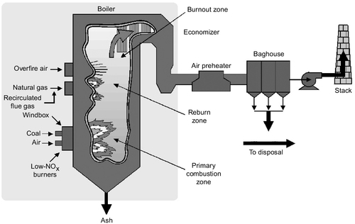
The initial combustion zone is normally the hottest region in the furnace. As the combustion gases leave this zone they start to cool. At this stage further air can be admitted (if combustion of the pulverized coal is still incomplete) to allow the combustion of the fuel to be completed, but at a lower temperature where the production of nitrogen oxide is reduced. The air admitted at this stage in the furnace is called overfire-air. When used in conjunction with controlled air admission in the main combustion zone, the use of overfire air can lead to a reduction in nitrogen oxide levels of 40–60%.
A third strategy that can reduce the nitrogen oxide levels even further is called reburning. This simply means that more coal, or natural gas, is introduced into the combustion gases after they have left the combustion zone. By this time gaseous oxygen levels in the flue gases will have been greatly reduced so that the new fuel will effectively steal oxygen from nitrogen oxide to combust. The effect is to remove some of the oxides of nitrogen that have been formed. Overall reductions of up to 70% can be achieved when all three strategies are applied. Low nitrogen oxide burners, overfire air, and reburning are all strategies that can be introduced into existing coal-fired power plants that do not have them, as well as being incorporated into new plants.
Sulfur dioxide removal
There are no combustion strategies that can be used to control the generation of sulfur dioxide in PC plants. If sulfur is present in coal it will be converted into sulfur dioxide during combustion. The only recourse is to capture the sulfur, either before the coal is burned using a coal-cleaning process, or after combustion using some chemical reagent inside the power plant.
There are many chemicals that are potentially capable of capturing sulfur dioxide from the flue gases of a power station but the cheapest to use are lime and limestone. Both are calcium compounds that will react with sulfur dioxide to produce calcium sulfate. If the latter can be made in a pure-enough form it can be sold into the building industry for use in wall boards.
One of the simplest methods of capturing sulfur dioxide is to inject one of these sorbent materials into the flue-gas stream as it exists the furnace (Figure 3.11). Reaction then takes place in the hot gas stream and the resultant particles of calcium sulfate, and of excess sorbent, are captured in a filter downstream of the injection point.
Depending on the point of injection of the sorbent, this method of sulfur removal can capture between 30% and 90% of the sulfur in the flue-gas stream. The cheapest, and least effective, method (30–60% capture efficiency) is to inject the sorbent directly above the furnace. Injection later in the flue-gas stream is more expensive but can remove up to 90% of the sulfur.
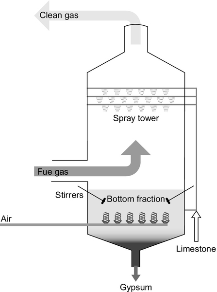
Sorbent injection into a flue-gas stream is one of the cheapest methods of capturing sulfur but it is not the most efficient. The best established method of removing most of the sulfur from the flue gas of a power plant is with a flue-gas desulfurization (FGD) unit, also called a wet scrubber. The FGD unit comprises a specially constructed, tall chamber through which the flue gas passes. In a typical scrubber, a slurry of water containing 10% lime or limestone is sprayed into the path of the flue gas where it reacts, capturing the sulfur dioxide. The slurry containing both gypsum and unreacted lime or limestone is then collected at the bottom of the chamber and recycled.
Typical wet scrubbing systems can capture up to 97% of the sulfur within the flue gas. With special additives, this can be raised to 99% in some cases. Wet scrubbers can easily be fitted to existing power plants, provided the space is available. Wet scrubbing technology is technically complex. It has been likened to a chemical plant operating within a power station. For this reason it requires skilled staff to operate. Nevertheless, it provides a proven method for removing high levels of the sulfur from a coal-fired power plant’s flue-gas stream.
A variation on the lime or limestone scrubbing system is the seawater FGD system. Instead of the calcium-based absorbents, this uses seawater pumped directly from the sea in the scrubbing tower to absorb sulfur dioxide. Seawater is naturally alkaline and will react with the sulfur dioxide, generating soluble sulfates that are carried away with the seawater and eventually released again into the sea. Seawater scrubbing can only be used when power plants are built on coastal sites but is claimed to be capable of 98–99% removal efficiency.
Other, more complex treatment systems have been tested including the use of activated carbon or charcoal. This is capable of absorbing both sulfur dioxide and nitrogen oxide and can eventually be regenerated, leaving pure sulfur as one by-product. Activated carbon can also absorb trace elements such as mercury.
Nitrogen oxide capture
As with sulfur dioxide, it is possible to remove nitrogen oxide after it has been formed in the flue gas of a power plant. The process involves the injection of either ammonia gas or urea into the flue-gas stream. Either chemical reacts with the nitrogen oxide present, converting the oxides into nitrogen and water.
If the ammonia or urea is injected into the hot flue-gas stream where the temperature is between 870 °C and 1200 °C, the reaction will occur spontaneously. This is called selective noncatalytic reduction (SNCR). At lower temperatures, the reaction is too slow, so a special metal catalyst is necessary to stimulate the reaction process. Where a catalyst is used, the process is called selective catalytic reduction (SCR).
SNCR will remove between 35% and 60% of the nitrogen oxide from the flue-gas stream. However, if care is not taken it can lead to contamination of fly ash with ammonia and to ammonia slip—the release of excess ammonia into the atmosphere. Nevertheless, it has been utilized at power plants in several parts of the world.
More widely used than SNCR is SCR. SCR units are commonly found on gas turbine power stations but may also be fitted to a coal-fired power plant where low nitrogen oxide combustion strategies do not reduce the emissions levels to below the regulatory limits (Figure 3.12). Typical flue-gas temperatures in an SCR unit are 340–380 °C. The hot gases pass over a solid catalyst that is normally made from a vanadium-titanium-based material or from a zeolite. The system is generally capable of removing 70–90% of the nitrogen oxide emissions from a flue-gas stream. Ammonia slip, although still possible, tends to be less of a problem.
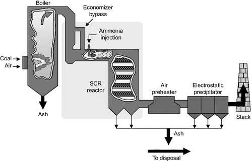
There are two major drawbacks to SCR. First, it can only be used with low sulfur coals (up to 1.5% of sulfur), and second, it is expensive. The catalyst requires changing every three to five years. In addition, sulfur in coal entering the SCR can be converted into trioxide (SO3), which becomes highly corrosive on contact with water when it forms sulfuric acid. This has to be carefully controlled or it can be extremely damaging both in the power plant and in the atmosphere.
It is also possible to remove nitrogen oxide using a wet scrubbing system. The reagent sprayed into the flue-gas stream in this case is a solution sodium hydroxide, although hydrogen peroxide has also been used. The reaction that takes place leads to the formation of nitrites and nitrates that must be isolated for disposal. Wet scrubbing is not normally used in power stations for nitrogen oxide removal.
Combined sulfur and nitrogen oxide removal
There are a number of processes that are capable, in principle at least, of removing both sulfur dioxide and nitrogen oxide in the same process. This ought to be more economical since only one process is needed instead of two. The use of activated charcoal has already been discussed as capable of treating both. Another is to use electron irradiation of the flue gases. Electrical discharge techniques have also been tested. However, none of these has yet been deployed widely commercially and most power plants rely on the well-tested processes described earlier.
Particulate (dust) removal
There are two principal systems for removing particulates from the flue gas of a coal-fired power station: electrostatic precipitators (ESPs) and fabric (bag house) filters.
Invented by the American scientist Frederick Cottrell, the ESP is well established and the technology has been widely exploited. It utilizes a system of plates and wires to apply a large voltage across the flue gas as it passes through the precipitator chamber. This causes an electrostatic charge to build up on the solid particles in the flue gas; as a result they are attracted to the oppositely charged plates of the ESP where they collect. Rapping the plates caused the deposits to fall to the bottom of the ESP where they are collected and removed. A new ESP will remove between 99% and 99.7% of the particulates from flue gas. However, it must be tuned to the particular coal being burned in the power plant. Where coals of different types and from various sources are to be burned, the alternative may be more effective.
Bag filters, or bag houses, are tube-shaped filter bags through which the flue gas passes on its way to the power plant stack. Particles in the gas stream are trapped in the fabric of the bags from which they are removed using one of a variety of bag-cleaning procedures. These include using supersonic blasts of air to dislodge particles so that they fall to the base of the unit and can be removed. These filters can be extremely effective, removing over 99% of particulate material. They are generally less cost effective than ESPs for collection efficiencies up to 99.5%. Above this, they are more cost effective. A system that combines a bag house–style filtration system with an ESP is under development too. This aims to provide a cost-effective high removal efficiency system, but has not yet been extensively demonstrated.
Mercury removal
Most coals contain a small amount of mercury and this can easily end up being discharged in the flue gas from a coal-fired power plant. In the United States the emission of mercury is to be regulated and proposals have also been put forward in the EU. This will necessitate the introduction of effective capture methodologies.
Dust removal systems in power plants will remove around 25% of the mercury released during combustion. When a wet scrubbing sulfur removal system is installed too this can increase to 40–60%. Adding SCR can lead to 95% removal with bituminous coals. However, sub-bituminous coals and lignites do not respond well so alternative measures may be needed to reduce mercury emissions to below regulatory limits.
The injection of activated carbon particles has been used to remove impurities such as mercury in waste incineration plants, and this appears to offer the best solution where further mercury capture is necessary. The carbon particles will then be removed in the dust removal system through which the flue gases pass at a later stage. It is expected that plants will eventually need to remove 90% or more of the mercury released during combustion.
Carbon dioxide removal
Limiting or completely removing carbon dioxide from the flue gases of a coal-fired power plant is likely to become necessary on new power plants after 2020. Even before that, increasingly onerous penalties for emitting the gas may make it necessary for power plant operators to find ways of curbing their carbon emissions (carbon emissions is often used as shorthand for carbon dioxide emissions). The technology to capture carbon dioxide already exists. It has not been deployed on a large coal-fired power plant but demonstration projects are being planned. However, this is only part of the problem. Carbon dioxide, once captured, must be stored (sequestered) in a way that prevents it ever entering the atmosphere. Otherwise the capture process will have been a waste of time. Therefore, carbon sequestering techniques must be perfected alongside carbon capture if the ultimate goal of carbon-emission-free coal combustion is ever to be realized.
For carbon capture there are three main approaches available. The first, often called post-combustion capture, involves installing a plant similar to an FGD scrubber to the exhaust of the power plant. Reagents capable of absorbing carbon dioxide are already available and this technology is likely to be one of the simplest and possibly the most economical to deploy. An alternative to this, called pre-combustion capture, involves pretreating coal to remove the carbon before combustion. This is achieved using a modified version of coal gasification that, when carried out fully, leaves a fuel gas composed primarily of hydrogen. The gasification process also requires some form of carbon dioxide capture technology, which may be via a scrubber system too. The third way of tackling carbon dioxide emissions attempts to sidestep the difficult problem of separating carbon dioxide from the flue gases, which are mainly composed of nitrogen after combustion is over. Instead, oxygen is separated from air first, and then coal is burned in virtually pure oxygen. The scheme, called oxy-fuel combustion, leads to an exhaust gas stream composed primarily of carbon dioxide, mixed with some water vapor and excess oxygen, from which it is much easier to isolate the carbon dioxide than when the latter is mixed with nitrogen.
There is a further method of reducing, though not eliminating, carbon dioxide emissions in a coal-fired plant: by replacing some of the coal with a biofuel. Biofuel cofiring, as this technique is known, cannot be used to eliminate all carbon emissions. For that to be possible the plant would have to burn biofuel alone, so it would no longer be a coal-fired plant. However, it can improve a coal plant’s environmental performance.
Post-combustion Capture
Biomass as a power plant fuel is generally considered to be carbon dioxide neutral. Combustion of biomass generates carbon dioxide in the same way as the combustion of coal but provided the biomass is derived from a source that is constantly replenished by regrowth. Then the new biomass that grows will absorb carbon dioxide from the atmosphere equivalent to that released during combustion.
Coal-fired power plants will burn biomass in exactly the same way as they burn coal. Depending on the amounts involved, the plant may require modification. Small quantities of biomass, up to perhaps 7%, can be simply mixed with the coal that is used to fire the plant without any adaptation being necessary. Pulverized coal and pulverized biomass enter the combustion chamber together and there is little change to operating conditions.
For the proportion of biomass to be increased beyond this, dedicated biomass burners must be used so that the conditions within the furnace can be more carefully controlled. With this technique up to 20% biomass can be introduced into a modern supercritical PC plant without adversely affecting its operation. This is also an advantageous means of using biomass because the efficiency of a modern coal-fired power plant will be much higher than of a dedicated biomass plant.
It is also possible to gasify biomass, generating a low-calorific-value fuel that can also be burned in a furnace. Introducing this gas rather than solid biomass into a coal-fired plant may offer some operational advantages. However, it does require a gasifier, making it more expensive and technically more complex than simple biomass cofiring.
Coal Gasification
The most straightforward approach to eliminating the carbon emissions resulting from coal combustion in a power station is to capture the carbon dioxide produced in a chemical absorption plant. This is similar in concept to an FGD scrubber for removing sulfur dioxide. Carbon dioxide capture is carried out today in a number of industries using a reagent called monoethylamine (MEA) and the process has even been applied on a small scale at a number of power plants to provide pure carbon dioxide for the foods industry. Ammonia and other amine reagents can also be used to capture carbon dioxide and this is a fertile area for research with a wide range of alternative absorbents and techniques being studied. These include cryogenic capture, solid rather than liquid absorbents, and membrane systems.
The key to any reagent for carbon dioxide capture is that the chemical reaction must be easily reversible so that the carbon dioxide can be released again and the reagent regenerated. Ease of capture depends on the concentration of carbon dioxide, which in the flue gases of a typical PC power plant will be around 14% by volume. At this concentration some form of chemical absorption process is necessary to achieve the required level of capture efficiency. This makes the regeneration more energy intensive than would be the case with a physical absorbent. Amines appear to be the best reagents available today but others may become available in the future.
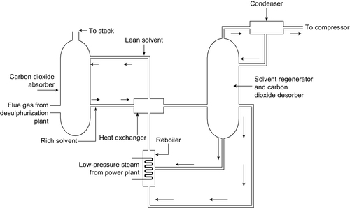
In a typical post-combustion capture plant the flue gases from the boiler are passed up a tall tower into which the reagent is sprayed so that gases and the liquid absorbent mix thoroughly (Figure 3.13). Depending on the column size, around 90% of the carbon dioxide within the flue gases can be removed in this way. The MEA reagent that has been sprayed into the path of the flue gases is collected at the bottom of the tower and then pumped to a second unit that heats it, releasing the carbon dioxide and returning pure MEA to enter the scrubbing tower once again. The regeneration process is extremely energy intensive, taking around 23% of the power output of the power station. A further 8% of the output is then needed to compress the carbon dioxide so that it can be transported for sequestration, and the MEA absorption plant uses a further 5% of the plant output as auxiliary power. This reduces the overall efficiency of power generation significantly. For example, an ultra-supercritical PC power plant that might achieve an efficiency of 45% would have this cut to around 35% with post-combustion capture. This has a large effect on the cost of electricity from such a plant.
Aside from its relative simplicity, one of the attractions of post-combustion carbon capture is that it can be applied retrospectively to existing power stations. This is unlikely to be cost effective for a large part of the old fleet of subcritical coal-fired power plants operating today, but it could be economical to retrofit newer and more efficient supercritical plants.
Oxy-fuel Combustion
When coal is burned in air, the carbon dioxide resulting from the combustion reaction is mixed with a large quantity of nitrogen along with a number of other constituents of air, pollutant gases, and particles generated during combustion. The carbon dioxide accounts for only around 14% of the mixture and removing this low concentration is relatively difficult. If, on the other hand, coal is burned in pure oxygen, then the flue gases resulting will be almost pure carbon dioxide. This will be mixed with the little nitrogen left over after oxygen purification, some water vapor, and the various pollutants generated. Isolating carbon dioxide from this mixture is much simpler than in the case of air combustion. This is the concept behind oxy-fuel combustion.
Oxy-fuel combustion essentially swaps a carbon dioxide separation plant for an oxygen separation plant so the efficiency of this plant now becomes key to the overall efficiency (Figure 3.14). Oxygen separation plants are widely used industrially but it is an energy-intensive process. Reducing the energy cost is likely to be important if the technology is to become successful.
Oxy-fuel combustion is not simply a matter of replacing the air with oxygen for combustion in a coal-fired plant. Other changes must be made too. When coal burns in oxygen the flame temperature can reach 2500 °C, far higher than current materials can stand. To overcome this, some of the carbon dioxide–rich flue gas from the exhaust of the boiler must be fed back and mixed with the oxygen, diluting it and reducing the flame temperature in the process.
Energy conversion efficiency for an oxy-fuel combustion PC plant appears to be slightly lower than for a plant with post-combustion capture; estimated efficiencies are in the range 29–32%, but since the technique has not yet been tested at a commercial scale, this remains speculative. However, like post-combustion capture, it is feasible to retrofit oxy-fuel combustion to an existing coal-fired power plant. Again this is only likely to be effective with a high-efficiency supercritical plant, but it does offer an interesting alternative for future carbon capture.
Biomass Cofiring
As noted before, coal gasification is another well-established industrial technique, used both as a source of domestic gas in the past and in the chemical industry to convert coal into a gas called synthesis gas or syngas that can be used as a precursor for a variety of chemical processes (Figure 3.15).
Coal gasification is carried out in a reactor called a gasifier where the fuel is burned under carefully controlled conditions with a strictly limited amount of either air or oxygen, together with steam. Oxygen gasifiers require a dedicated oxygen plant. The partial combustion of the coal, according to the reaction shown earlier, results in a gas that is primarily a mixture of hydrogen and carbon monoxide together with various combustion impurities such as hydrogen sulfide. A residual char is left.
Syngas still contains carbon in the form of carbon monoxide, so to create a carbon-free gas this must be passed through a second reactor where it is mixed with further steam and passed over a catalyst that converts the carbon monoxide into carbon dioxide and further hydrogen:
![]()
This process is called the water-shift reaction.
This mixture of carbon dioxide and hydrogen must now be cleaned and then the carbon dioxide separated. The latter is in much higher concentration than in the flue gases of a coal-fired power plant, accounting for around 50% of the mixture, and it can be separated using a physical absorbent rather than one that reacts chemically with the gas. The physical absorbent binds the carbon dioxide more loosely than a chemical absorbent such as MEA would, so releasing the carbon dioxide and regenerating the solvent is much less expensive from an energetic point of view. Reagents based on glycol and refrigerated methanol are used industrially to separate hydrogen from carbon dioxide, and these could be applied in a power plants based on gasification too.
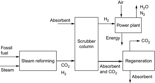
To produce electricity from coal in this way, the hydrogen is burned in a gas turbine–based combined cycle power plant that is closely integrated with the gasification process to achieve the highest efficiency possible. This configuration is a variation of the IGCC power plant already described. As with the other approaches to carbon dioxide capture and removal, this leads to a significant fall in efficiency, and an IGCC plant with carbon capture appears likely to have an energy conversion efficiency of around 32%, broadly similar to the other technologies discussed earlier.
An alternative to an IGCC plant is to use the hydrogen produced by the gasification process as fuel for a fuel cell. These devices, which are potentially capable of high efficiency when operating with pure hydrogen, will be discussed in a later chapter.
Carbon dioxide sequestration
If carbon dioxide is to be captured during the use of coal (or any other fossil or carbon-based fuel) for electricity generation, then it must also be stored in such a way that it cannot ever enter the atmosphere. Otherwise the capture is pointless.
Various methods are being explored for achieving this but the most likely solution is that the carbon dioxide will be stored underground (Figure 3.16). Several options exist for this. One of the most obvious is to pump it into exhausted oil and gas fields. The infrastructure already exists to carry this out and carbon dioxide has been pumped into older oil fields to enhance oil recovery for many years so the technology is well understood. Questions remain about the security of the gas once it has been sequestered in this way, but in principle it could provide a safe means of storing the gas.
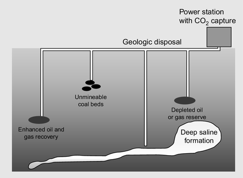
Exhausted wells offer a first choice for testing capture and sequestration technology, but they cannot provide the capacity that will be needed if this is to become a global practice. For that, underground geological formations such as aquifers are likely to be used. These are sites where an impermeable rock cap traps liquids beneath it. Carbon dioxide can be pumped into such aquifers where it first displaces the brine already trapped there and eventually dissolves in it, potentially forming solid salts that are permanently held.
Some consideration has also been given to storing carbon dioxide in the world’s oceans. These are already the largest global carbon dioxide sinks, holding around 20 times as much carbon dioxide as there is in the atmosphere and biosphere combined. However, there are too many uncertainties attached to this method of carbon dioxide disposal for it to be used today.
Once carbon sequestration sites have been found and stores established, then the carbon dioxide must be delivered to them. In most cases this is likely to be via a new carbon dioxide pipeline system. The gas must first be pressurized and then it can be pumped from power plants to the storage sites. The gas is normally pressurized between 10 MPa and 15 MPa, when it enters a supercritical state under which it has the density of a fluid though it can still behave like a gas. Tanker transportation might be feasible under some circumstances but it does not appear as economical as pipeline transportation.
Cost of coal-fired power generation
Coal-fired power stations are relatively expensive to build since their construction involves both large quantities of expensive materials, such as iron and steel, and large volumes of labor. While some parts of a coal-fired power plant such as its steam turbines can be assembled in a factory and then delivered to the site, much of the assembly of the boiler and flue-gas cleaning systems must take place at the site itself. As a consequence, the cost of a coal-fired power plant will be vulnerable to changing commodity costs and generally increasing labor costs.
Against this the fuel (coal) is generally the cheapest of fossil fuels and this will normally outweigh the high capital cost so that the cost of electricity from a coal-fired power station will be among the most competitive available. Currently, coal-fired power stations are built without carbon capture facilities but this is likely to be required at some point during the third decade of the 21st century. It is also likely that plants built before that time will be required to be carbon-capture ready so that post-carbon-capture technology can be fitted at a later stage. All this needs to be taken into account when considering construction of a coal-fired power generating facility.
Table 3.6 shows the estimated 2011 cost of coal-fired power plants in the United States in 2010 dollar prices based on data from the U.S. government’s Energy Information Administration. This analysis suggests that the capital cost of an advanced PC power plant is $3167/kW. When carbon capture and storage is added to this, based on post-combustion capture, the cost rises to $5099/kW, an increase of 60%.
Table 3.6
Cost of Coal-fired Power Plant Technology
| Type of Coal-fired Power Plant | 2011 Capital Cost ($/kW) |
| Advanced pulverized coal plant | 3167 |
| Advanced pulverized plant with carbon capture and storage | 5099 |
| Integrated gasification combined cycle plant | 3565 |
| Integrated gasification combined cycle plant with carbon capture and storage | 5348 |
Source: Updated Capital Cost Estimates for Electricity Generation Plants, U.S. Energy Information Administration, 2010.
An integrated gasification combined cycle power plant without carbon capture and storage would, on the same basis, have cost $3565/kW in 2011. However, when carbon capture and storage is added to this plant, based on the type of system discussed before, the price would rise to $5348/kW. The cost of an oxy-fuel combustion plant was not included in the analysis but other analyzes suggest that the cost is likely to be similar to those in Table 3.6 for the other technologies with carbon capture.
Other analyses suggest that future costs will be lower than this. Table 3.7 shows another set of figures for the cost of future coal-fired power plants, in this case as estimated by the U.S. Electric Power Research Institute (EPRI). This analysis is based on the assumption that carbon dioxide capture will not be deployed by 2015. The cost of a PC power plant in that year, again calculated in 2010 U.S. dollars, is estimated to be between $2000/kW and $2300/kW. At the same time, the cost of an integrated gasification combined cycle plant is put at between $3150/kW and $3450/kW.
Table 3.7
Capital Costs in 2015 and 2025 for Various U.S.-generating Technologies (2010 U.S.$)
| Type of Coal-fired Power Plant | 2015 ($/kW) without Carbon Dioxide Capture | 2025 ($/kW) Carbon Capture and Storage |
| Pulverized coal-fired plant | 2000–2300 | 2600–2850 |
| Integrated gasification combined cycle plant | 3150–3450 | 3100–3800 |
Source: Program on Technology Innovation: Integrated Generation Technology Options, Technical Update June 2011, Electric Power Research Institute, 2011. (EPRI reference 1022782.)
EPRI has assumed that carbon capture and storage will be necessary in 2025. By then the cost of a PC plant with carbon capture and storage is estimated to be $2600–2850/kW. For an integrated gasification combined cycle power plant the cost range is $3100–3800/kW. As before, there is no consideration of an oxy-fuel combustion plant, but the cost of this can be expected to fall somewhere within the cost range of the two other technologies, $2600–3800/kW.
All these costs are for power plants built in the United States. While costs are likely to be similar in Europe, commodity prices and especially labor costs are likely to differ widely in other parts of the world and this can affect the capital cost significantly. Costs in countries like China and India are consistently much lower than in the United States and Europe.