
Fuel Cells
Abstract
Fuel cells are electrochemical devices that consume hydrogen and oxygen to produce electricity. They are not heat engines, therefore they are not restricted by the heat engine thermodynamic limits. A number of different types of fuel cells have been developed, each with different characteristics. The alkaline fuel cell is very efficient but also expensive. The phosphoric acid fuel cell has achieved the biggest commercial success, particularly in packaged combined heat and power modules for distributed generation applications. The proton exchange membrane fuel cell is very light and also potentially of high efficiency, making it attractive for automotive applications. The molten carbonate and the solid oxide fuel cells are both high-temperature cells and can provide high-grade heat suitable for further power generation, making them capable of high efficiency too. The direct methanol fuel cell can consume liquid methanol and is attractive for portable applications as a battery replacement.
The fuel cell is an electrochemical device, closely related to the battery, which harnesses a chemical reaction between two reactants to produce electricity. A battery is usually intended as a portable or self-contained source of electricity, and it must carry the reactants it needs to generate electricity within it. Once they are exhausted the battery can no longer supply any power. A fuel cell, by contrast, does not contain any chemical reactants itself but is supplied with them from an external source. So long as these reactants are made available, the cell will continue to provide power.
Batteries come in many different forms, each exploiting reactions between a variety of different chemicals to generate electricity. Fuel cells are unique in that almost all of them exploit a single reaction—that between hydrogen and oxygen to produce water. (There is one exception, the direct methanol fuel cell, which utilizes methanol and oxygen and produces carbon dioxide and water as its by-products.) The simplicity of the basic fuel cell reaction makes it both technically and environmentally attractive—the latter since the only by-products are water and some heat. However, in practice, fuel cells are not quite so simple.
The oxygen for a fuel cell can be supplied from air and air is normally provided to one of the cells electrodes. However, there is no ready source of hydrogen available today. To overcome this, most fuel cells utilize natural gas that they convert to hydrogen in a process known as reforming. This generates carbon dioxide as a by-product, somewhat tarnishing the otherwise spotless environmental credentials of the fuel cell. Even so fuel cells are relatively benign, environmentally, compared to other fossil fuel–generating technologies.
Aside from its environmental performance, one of the most attractive features of the fuel cell is the fact that its energy conversion process is not limited by Carnot cycle thermodynamics that restrict the ultimate efficiency at which any type of heat engine can operate. The best practical simple cycle heat engine efficiency is 50%, achieved in a diesel engine. By contrast, the best fuel cell—an alkaline fuel cell provided with hydrogen reactant—can achieve 60% efficiency today.
The theoretical maximum efficiency for a hydrogen fuel cell operating at room temperature is 83%, but in practice most fuel cells operate at elevated temperatures, reducing efficiency. However, some high-temperature fuel cells can operate in a variety of combined cycle configurations allowing additional gains in efficiency. Meanwhile, overall cycle efficiency is reduced when natural gas must be reformed since this is an energy-intensive reaction. Even so, practical cells are competitive on an efficiency basis with other fossil fuel technologies. If a hydrogen economy ever develops, with hydrogen replacing natural gas as the primary gaseous fuel, then fuel cells should be able to outperform the competing combustion technologies with ease.
The fuel cell has other advantages too. The cell itself has no moving parts and can operate for long periods without maintenance—far longer than any turbine or engine-based generating system. The absence of moving parts makes them inherently quiet too (although this is limited by the use of mechanical pumps, which generate noise), and they emit relatively low levels of pollution compared to other types of generating system based on fossil fuel.
With so much going for them, why are there no fleets of fuel cell power plants today? The answer is cost. While the fuel cell principle has been known since the first half of the 19th century, development of a cheap version of the device has proved extremely challenging. As a result, the first commercial fuel cells only appeared in the early 1990s. Since then research into a wide range of fuel cells has advanced and a variety of commercial units are available. Cost still remains a challenge, but interest in fuel cells as potential power units for vehicles has spurred research that could see some types eventually achieve competitively low prices. Meanwhile, domestic heat and power units based on fuel cells are opening potential new markets for these devices.
History of fuel cells
If a voltage is applied to water by placing two electrodes into the liquid and connecting a battery across them, the voltage induces a chemical reaction; hydrogen is produced at one electrode and oxygen at the other. Electrical energy is being used to force the reaction that causes water to dissociate into hydrogen and oxygen.
In 1839, Sir William Grove observed that this process, known as electrolysis, will proceed in the other direction too, and of its own accord. If two specially selected electrodes are placed in water and gaseous hydrogen and oxygen provided (one gas at each electrode), hydrogen will react at one electrode and oxygen at the other, producing water and an electrical voltage between the electrodes. This is the basis of fuel cell operation.
Although the principle was known in 1839, it was not until a century later that the English scientist Francis Bacon was able to develop a practical fuel cell. He demonstrated a 5 kW fuel cell stack in 1959 that he patented as the Bacon Cell. In the same year, Harry Ihrig, an engineer working for the Allis Chalmers Manufacturing Company, demonstrated a 20 horsepower tractor powered by fuel cells. Both were based on the alkaline fuel cell.
By the early 1960s, the Pratt and Whitney Aircraft Corporation had licensed Bacon’s fuel cell and began to develop the technology. At around the same time, scientists at U.S. company General Electric began to develop fuel cells based on proton exchange membranes. When NASA was planning its manned space program it identified fuel cells as the ideal power source for its space vehicles. Initially the organization chose the General Electric design and this was used in the Gemini space program. Subsequently it switched to the alkaline fuel cell for the Apollo program and this continued to be used in the space shuttle until it was decommissioned.
Interest in these and other fuel cells continued in the 1960s, 1970s, and 1980s, and a variety of new types of fuel cell were pursued. This led, in 1992, to the launch of the first commercial fuel cell by a company called International Fuel Cells, the parent company of which, United Technologies, owned Pratt and Whitney. This new fuel cell was based on a new acidic electrolyte called phosphoric acid, and the phosphoric acid fuel cell has since developed into the most successful commercial type of cell.
Meanwhile, environmental concerns that began to arise in the 1980s together with fears about oil supply led at the beginning of the 1990s to a revival of an old quest to develop practical electric vehicles that could replace the petrol engine car. While several potential technologies have been pursued, one of the leading contenders is a fuel cell power unit based on proton exchange membrane fuel cells. Development of these continues to receive high levels of investment.
Other types of fuel cell have also been developed. Among these are two high-temperature fuel cells: the molten carbonate fuel cell and the solid oxide fuel cell. The latter is an all solid-state fuel cell, making it potentially extremely durable. Alkaline fuels remain under development too and a sixth type, the direct methanol fuel cell, is seen as a potential new portable source of power.
Fuel cell principle
The fuel cell principle belongs to a branch of chemistry called electrochemistry. This explores how electricity can be derived from a chemical reaction. In nature certain materials will react with one another spontaneously if the conditions are correct. For example, a strong acid like sulfuric acid will react vigorously with a variety of different materials if they are mixed with it. Other reactions will also proceed spontaneously but require a kick-start. Typical of these is the reaction of hydrogen with oxygen. The two gases can be mixed at ambient temperatures without any reaction, but once the temperature is raised beyond a certain point, with a spark for example, the reaction will proceed explosively.
Spontaneous reactions of this type are called exothermic reactions because they all release heat energy when they are allowed to proceed freely. All the chemical reactions that can be exploited to generate electrical energy are spontaneous reactions. However, when the reaction is exploited electrochemically, the progress of the reaction is managed in such a way that some of the energy that would normally be released as heat emerges instead as electrical energy.
The reaction between hydrogen and oxygen is exothermic. This reaction can be expressed by a simple chemical formula:
![]()
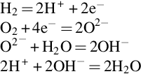
The formula shows two hydrogen molecules and one oxygen molecule reacting to create two molecules of water. Although the formula looks simple, this is in fact a relatively complex process, but it can be broken down into three simple partial reactions, each of which must take place for the reaction to run to completion. The first of these involves the hydrogen molecule, H2, splitting into two hydrogen atoms, H, and each of these releasing an electron to form a positively charged hydrogen ion, a proton:
![]()
A parallel second partial reaction involves the oxygen molecule, O2, which splits into two oxygen atoms, O. Each of these absorbs two electrons released from two hydrogen atoms to produce a doubly negatively charged oxygen ion, O2 −:
![]()
The third and final part of the reaction involves the negatively charged oxygen ion attracting two positively charged hydrogen atoms and the three ions coalescing to form a water molecule, H2O:
![]()
Then the reaction is complete.
When hydrogen burns in air, the various steps of the reaction occur in the same place at the same time. However, in a fuel cell the hydrogen and oxygen are not allowed to mix. Instead, the reacting gases are introduced separately with hydrogen supplied to one electrode of the cell and oxygen to the other. The two electrodes are separated by a material called the electrolyte.
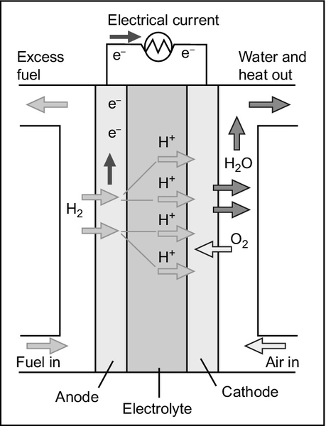
The electrolyte is the key element in any electrochemical cell (Figure 7.1) because it acts like a filter to both stop the cell reactants mixing directly with one another and to control how the charged ions created during the partial cell reactions are allowed to reach each other. The electrolyte in a fuel cell is impermeable to the gases, hydrogen and oxygen. It will not conduct electricity in the form of electrons either, nor (provided it is an acidic electrolyte) will it conduct the negatively charged oxygen ions. What it will do is conduct positively charged hydrogen ions.
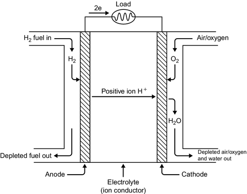
At the hydrogen electrode (called the anode) hydrogen molecules first adhere to the electrode material and then separate into atoms, each subsequently releasing an electron to form a positively charged ion as shown in the preceding equations. In this ionic form the hydrogen can cross the electrolyte boundary and reach the oxygen at the second electrode. The electrons, however, are left behind at the electrode.
At the second electrode (called the cathode) oxygen atoms will also adhere to the electrode surface and dissociate, each leaving two oxygen atoms. However, these require a supply of electrons if they are to form oxygen ions. Only in this form can they coalesce with the hydrogen ions traveling through the electrolyte from the anode to create water molecules. The electrons must come from the anode, but these electrons cannot pass through the electrolyte.
If an electrical connection is made between the two electrodes the electrons can now pass through the connecting wire to the oxygen atoms where they will create oxygen ions, allowing the reaction to run to completion. When a small electric light bulb is inserted into this circuit it will glow, proving that an electric current is indeed flowing between one electrode and the other.
All electrochemical cells operate in this way. While part of the reaction can take place within the confines of the cell, it can only be completed if electrons are allowed to travel from one electrode to the other through an external circuit.1 If no connection is made the exothermic nature of the reaction means that a charge builds up at each electrode, creating an electrical potential, the cell voltage, which will drive electrons from one electrode to the other when a connection is made.
Since the electrolyte is such an important part of an electrochemical cell, fuel cells are generally identified by the type of electrolyte they employ. Phosphoric acid fuel cells use phosphoric acid, which being acidic is a proton (positively charged hydrogen atom) conductor. Proton exchange membrane cells also rely on an acidic membrane to allow hydrogen ions to pass. The alkaline fuel cell is a hydroxide ion (OH−) conductor; the hydroxide ion is the complement in water of the hydrogen ion. Meanwhile, the high-temperature solid oxide fuel cell uses a solid that is a conductor of oxygen ions. Other fuel cell reactions appear more complex even though the end result is the same. So, for example, the molten carbonate fuel cell electrolyte conducts carbonate ions.
Catalysts
The preceding description of the operation of a fuel cell is a simplification because it omits one key feature of the reaction between hydrogen and oxygen. Although hydrogen atoms and oxygen atoms will react spontaneously to form water, both hydrogen and oxygen are found (at room temperature) in the molecular forms H2 and O2. These hydrogen and oxygen molecules must split into atoms before the reaction will proceed, but they will not do so spontaneously because of the chemical bond holding each molecule together, even though these bonds are much weaker than the chemical bonds that will bind them together into a water molecule. The energy needed to cause the individual molecules to dissociate into atoms creates an energy barrier called the activation energy that must be overcome before the highly exothermic reaction between the atoms can take place.
One method of splitting the molecules is to raise their temperature. They will start to dissociate rapidly between 800 °C and 1000 °C. A flame or a spark will be hot enough to split sufficient of the molecules to start the reaction, which then generates so much heat spontaneously that it keeps the reaction going until all the hydrogen or oxygen is used up. Some fuel cell designs use high temperatures to encourage the gas molecules to dissociate, but high temperatures bring their own design and materials problems.
The alternative is to use a catalyst. A catalyst is a component that is needed for a reaction to take place but is not actually consumed during the reaction. As such, it is usually used to accelerate a reaction that will otherwise take place slowly. In the case of the fuel cell the best catalyst for low-temperature acceleration of the reaction is metallic platinum. The platinum acts by attracting the hydrogen and oxygen molecules that will preferentially stick to its surface in dissociated form, generating a supply of the atoms needed for the fuel cell reaction to take place. In its presence, the reaction can take place below 100 °C.
Platinum, even though it is only required in small quantities in a fuel cell, is expensive and this helps to elevate the cost of the cells themselves. A key area of fuel cell research is therefore directed at finding cheaper alternatives. Platinum is also very sensitive to impurities in the gaseous reactants that can poison it, rendering it ineffective. Sulfur dioxide is a particular problem and so is carbon monoxide, both of which can find their way into hydrogen generated by the reforming of natural gas or other fuels. This is another reason why alternative catalysts, which are less sensitive to poisoning, are being sought.
Hydrocarbon gas reformation
A fuel cell is designed to “burn” hydrogen and oxygen to generate electricity. Hydrogen is not generally available, but hydrocarbon gases such as natural gas or even gases generated from biomass can be converted into hydrogen in a process known as reformation. The reformation reaction generates a gas that contains a mixture of carbon dioxide and hydrogen that can then be supplied as a reactant for the fuel cell. (The carbon dioxide will be inert and so will not interfere with the reaction other than by acting as a diluent for the hydrogen.) The main constituent of natural gas and of most biogas is methane, and this is the main target for the standard reformation process, although other hydrocarbons can also be reformed and even coal can be converted into a hydrogen-rich fuel if necessary (see coal gasification in Chapter 3).
The conversion is usually carried out as a two-stage process. In the first stage the methane-rich gas is mixed with water vapor and passed over a catalyst at a high temperature where the gases react to produce a mixture of hydrogen and carbon monoxide, a process called steam reforming. A second reaction, called the water shift reaction, is then carried out during which additional water vapor is added to the new mixture where it reacts with the carbon monoxide, again in the presence of a catalyst, to produce more hydrogen and carbon dioxide.
The degree to which this second stage reaction is carried to completion is extremely important for fuel cells because the catalysts in low-temperature cells are sensitive to carbon monoxide poisoning. In consequence, virtually all the carbon monoxide must be removed from the fuel before it is fed into the fuel cell. Natural gas can also contain some sulfur impurity. This is normally removed by cleaning before the fuel is reformed, but if not, then any remaining sulfur must be removed since low-temperature fuel cell catalysts are extremely sensitive to its presence.
While natural gas is the most convenient source of hydrogen for a fuel cell today, other fuels can also be exploited. For example, methanol can also be converted in to a hydrogen-rich gas using a reforming process, as can gasoline, though the latter requires an extremely high temperature (800 °C). Both these processes are of interest to the automotive industry.
Since reforming of all these fuels takes place at a relatively high temperature, low-temperature fuel cells have to be equipped with an external reformer to process the fuel before it enters the fuel cell. However, heat generated within the fuel cell may be used to help drive the reforming process. The conditions inside the two main types of high-temperature fuel cells are sufficient for the reforming to take place within the cell itself, simplifying system design.
While a fuel cell burning hydrogen and oxygen produces no carbon dioxide, most fuel cells will generate carbon dioxide because they derive their hydrogen from natural gas or another carbon-containing fuel. When methane is converted into hydrogen it generates exactly the same amount of carbon monoxide as it would have generated if it had been burned in a gas turbine. However, if hydrogen can be generated without the need for fossil fuel combustion—by using hydropower to electrolyze water, for example—then burning the gas in a fuel cell provides an efficient and emission-free source of electricity.
Fuel cell efficiency
The reaction between hydrogen and oxygen to create water releases a precisely quantified amount of energy. Not all this energy can be converted into electricity because some is required to overcome the energy barrier that normally prevents the reaction proceeding. When this reaction takes place between oxygen and hydrogen, each provided at a pressure of one atmosphere and at room temperature, the theoretical maximum chemical-to-electrical energy conversion efficiency that can be achieved is 83%.
This efficiency is an ideal and no cell would be able to achieve that figure. The precise reaction conditions will affect the potential efficiency too. If the pressure of the reacting gases is increased, then conversion efficiency can be increased. On the other hand, increasing the operational temperature of the cell will reduce the overall efficiency that can be achieved.
The actual conversion efficiency of a fuel cell is reflected in the voltage that the cell produces between its terminals. The theoretical maximum cell voltage at open circuit for a fuel cell operating at room temperature, when the cell is delivering no current, is 1.229 V. In practice, such a cell would deliver a voltage less than this because of losses resulting from the internal resistance of the cell and activation energy barriers of various sorts at electrode interfaces.
This theoretical maximum voltage only applies to a cell where the cell reaction product is water in liquid form. In most practical cells, where the product is actually water vapor, this maximum falls to 1.18 V. At 100 °C this falls to 1.16 V, and at 800 °C the ideal cell voltage is only 0.99 V. This is equivalent to a maximum ideal efficiency of 67%. In practice, high-temperature cells might approach 50% efficiency. Low-temperature cells can do better than this.
While high-temperature cells are ostensibly less efficient, the loss of electrochemical efficiency is not necessarily a major handicap. The heat generated within the cells can be exploited either to produce more electricity in some form of hybrid system, or it may be utilized in a combined heat and power system, providing useful heat as well as electricity.
Fuel cell types
There are six principal types of fuel cell that are of interest to the power generation market. They are listed in Table 7.1 together with their primary characteristics.
Table 7.1
Fuel Cell Characteristics
| Operating Temperature (ºC) | Catalyst | Efficiency (%) | |
| Alkaline fuel cell | 25–200 | Noble metal catalyst | 60 |
| Phosphoric acid fuel cell | 150–200 | Platinum | 35–42 |
| Proton exchange membrane fuel cell | 80 | Platinum | 30–50 |
| Molten carbonate fuel cell | 650 | Nickel | 47 |
| Solid oxide fuel cell | 750–1000 | None needed at temperatures used | 35–43 |
| Direct methanol fuel cell | 60–130 | Platinum/ruthenium | 25–40 |
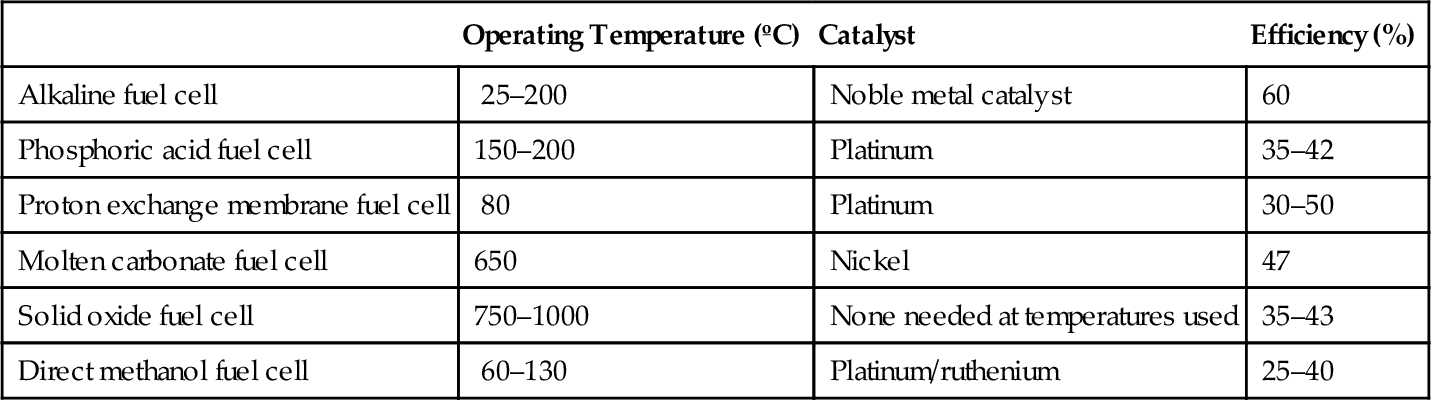
The alkaline fuel cell is the earliest fuel cell to be developed and it still remains under active development. Early AFCs operated between 150 °C and 200 °C, but more recent designs allow the cell to operate at a much lower temperature of 25–70 °C. The cell electrolyte is a solution of potassium hydroxide. AFCs have achieved the highest efficiency of any fuel cell with practical efficiencies of 60% in the space shuttle and experimental efficiencies of 70%.
The phosphoric acid fuel cell was the first to achieve commercial success for mainstream power generation. It too is a low-temperature cell with an operating temperature of 150–200 °C and an acidic electrolyte composed of phosphoric acid. Practical cell efficiencies of 42% have been recorded. The proton exchange membrane fuel cell is being developed as a potential automotive power source. Its electrolyte is primarily water so standard cells must operate below 100 °C. Efficiencies up to 50% are achievable in practice and up to 60% may be possible with a pure hydrogen fuel source.
Two high-temperature fuel cells have also reached a high stage of maturity. The molten carbonate fuel cell operates around 650 °C and can reach 47% efficiency, while the solid oxide fuel cell, with an operating temperature range of 750–1000 °C depending on the electrolyte, can achieve 43% efficiency in large units. Both high-temperature cells can also be incorporated into hybrid cycles to increase overall generation efficiency.
The sixth type of cell is the direct methanol fuel cell. This is another type of polymer membrane cell with an operating temperature up to 130 °C. The fuel fed to the anode is methanol mixed with water, which can be consumed directly without reforming. The fact that the cell can operate with a liquid fuel makes it attractive both for automotive applications and for portable equipment such as computers and mobile phones. Practical efficiencies are low at around 25%, although experimental cells have reached 40%.
Alkaline Fuel Cell
The alkaline fuel cell (AFC) employs an electrolyte composed of a concentrated solution of potassium hydroxide (Figure 7.2). This is the alkali that has the highest conductivity of the alkaline hydroxides. The earliest practical cell of this type, developed by Francis Bacon, used a concentration of 45%. The cell requires a metal catalyst such as platinum, but the actual metal used varies with application.
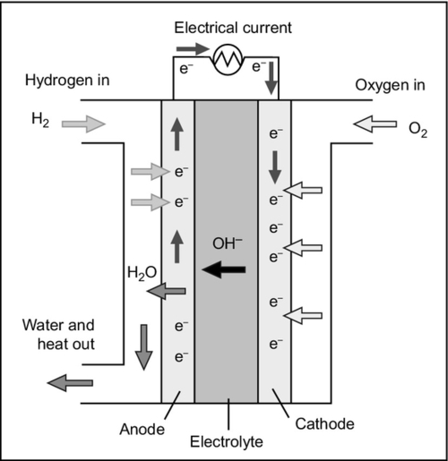
The cell reaction in the AFC is slightly different to the standard fuel cell reaction because the electrolyte conducts hydroxide ions (OH−) rather than protons. Molecular hydrogen is supplied to the anode where it splits into hydrogen atoms that each release an electron to form a hydrogen ion. Meanwhile, at the cathode oxygen molecules dissociate to form atoms, but in this case they take up two electrons and then react with water to form hydroxide ions. These can then pass through the electrolyte to the anode where they react with the hydrogen ions generated there to regenerate water. The series of reactions are as follows:
In essence, the reaction is exactly the same as the standard fuel cell reaction described before but it is mediated by the hydroxide ions. These are generated at the cathode in the reaction between oxygen ions and water and then consumed at the cathode.
Early AFC cells operated at a relatively high temperature around 260 °C and some modern cells use similar temperatures. Other modern cells utilize much lower temperatures with the cells in the space shuttle operating at 85–95 °C. These cells are capable of practical efficiencies of 60%. Developers are hoping to develop cells that can operate at ambient temperature.
In a classic AFC cell used in the space program the electrolyte is held within a porous solid matrix of an asbestos-like material. Electrodes are generally exotic to achieve the high efficiencies required for such applications. Space shuttle cell anodes were 80% platinum and 20% palladium carried on a silver-plated nickel mesh and cathodes 90% gold and 10% palladium on a similar mesh. For less demanding applications simpler catalysts can be employed.
Cell lifetime has so far been the main factor limiting the use of the AFC. The lifetime of a space shuttle fuel cell was around 2600 hours. Modern developments have begun to extend this and a lifetime of 5000 hours appears feasible over the short term. Limiting factors include the buildup of potassium carbonate generated from carbon dioxide both in air and as an impurity within the hydrogen fuel.
As will other fuel cells, the AFC requires hydrogen and oxygen. The space program cells used high-purity hydrogen and oxygen as fuel, but for terrestrial applications air is preferred for the cathode. This must be treated first to remove all traces of carbon dioxide. There are sources of pure hydrogen such as hydrazine, but for practical applications reformed natural gas is the best source. However, this also must be purged of carbon dioxide to maintain cell health.
One of the key recent AFC developments is the use of a circulating electrolyte rather than an electrolyte immobilized within a matrix. Cycling the electrolyte allows carbonate impurities to be removed, potentially increasing cell lifetime. Other research is aimed at developing hydroxyl ion exchange membranes similar to the proton exchange membranes already developed for acidic fuel cells.
There are a small number of companies currently developing AFCs and the availability of commercial cells is limited. They are only used today where efficiency and reliability are more important than cost. Outside the space program this has been restricted to a number of vehicle applications such as fork-lift trucks and golf trolleys. Costs are too high and lifetimes too short for their use for general automotive applications, but if both could be reduced they would have great potential.
Phosphoric Acid Fuel Cell
The phosphoric acid fuel cell (PAFC) uses an electrolyte composed of pure phosphoric acid, H3PO4 (Figure 7.3). This acid, which is a solid up to 42 °C, is a relatively poor conductor of hydrogen ions but is stable in liquid form to just above 200 °C, so it can form the basis of a fuel cell that operates using hydrogen and oxygen supplied as air. Most PAFCs operate between 150 °C and 200 °C.
The electrolyte, once liquefied, is contained in a silicon carbide matrix where it is held within the pores of the material by capillary action. Since the electrolyte is a liquid, care must be taken to control evaporation or migration as this will impair the operation of the cell. PAFCs are generally operated at atmospheric pressure but higher-pressure operation is possible. This will increase efficiency but may also lead to higher cell corrosion rates by increasing the reactivity of the acidic electrolyte.
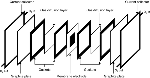
Electrodes for the cell are made from porous carbon paper that is heat-treated to create a large surface area and then coated with a fine layer of platinum or platinum alloy onto which the gaseous reactants can be absorbed. These electrodes are bonded to the electrolyte-supporting matrix using Teflon mounts. There are grooves in the back of the electrodes that carry the hydrogen or oxygen to each cell. Carbon is a good electrical conductor, so it can also be used to transport the current from the cells. Each cell produces a voltage around 0.65 V. Cells can be connected back-to-back, in series, to build what is known as a stack. Stacks are then connected in parallel to provide the required current and voltage output.
The PAFC requires hydrogen and oxygen, the latter from air. The cell must be heated to its operating temperature before it can be started, but once it starts operating the cell reaction produces sufficient heat to maintain its temperature. Water generated at the cathode by the cell reaction emerges as water vapor, which is swept away from the cell in the airstream feeding oxygen to the cathode. It is important that water removal is effective. Otherwise, the water might dissolve in the electrolyte.
Most modern cells operate at the highest temperature that is practical, close to 200 °C, to reduce the sensitivity of the catalyst to poisoning and to ensure that all the water from the cell reaction is produced in vapor form. Above this temperature the electrolyte starts to decompose and becomes more aggressive in its reactivity, particularly with the carbon components of the cell. At the cell operating temperature the hydrogen–oxygen reaction will proceed sufficiently swiftly with a platinum catalyst to sustain cell operation. However, the concentration of carbon monoxide in the hydrogen must be kept below 1.5% to prevent catalyst poisoning. Sulfur tolerance is virtually zero, so this must be scrupulously removed too.
Hydrogen for cell operation is normally provided by reforming natural gas and packaged PAFC units include a reformer. Heat generated within the cell during operation can be used to help drive this reaction. Other fuel sources are possible too, including biogas. The reforming of natural gas or biogas produces carbon dioxide, but the low-temperature reforming process does not produce significant amounts of nitrogen oxide and other emission levels are low.
Practical cell efficiencies between 36% and 42% are typical, with higher efficiencies generally achieved with pressurized operation. The operational temperature makes PAFC units suitable for combined heat and power (CHP) generation, producing hot water. Packaged CHP units can reach up to 87% energy utilization. PAFC lifetimes up to 40,000 hours have been recorded, providing good operational potential, and developers plan to extend this further. They have been operated at temperatures as low as − 32 °C and as high as 87 °C.
Most of the development of PAFCs has taken place either in the United States or Japan. The U.S. company United Technologies Corporation (UTC) launched the first commercial units in 1992 with an electrical output of 200 kW. The newest version of this cell is now available in 200 kW and 400 kW unit sizes. Both can also provide hot water. UTC has worked in partnership with the Japanese company Toshiba. Fuji Electric Corporation and Mitsubishi Electric have also been active in PAFC development, and the former is marketing a 100 kW unit. In all cases larger capacity can be achieved with multiple units.
The applications of PAFC units are varied but many have been installed to provide power and heat in institutions, such as hospitals, at commercial sites, and in office blocks. They are also suitable for backup use. Early cells were expensive and they appeared to have little future at the beginning of the 21st century as other types of cells reached maturity. However, the development of those other cells has been much slower than expected. In the meantime the continued development of PAFC units and an increase in their market size, leading to economies of scale, has meant that prices have fallen. At the end of the first decade of the 21st century they were the most successful of all fuel cells for power generation applications.
Proton Exchange Membrane Fuel Cell
The proton exchange membrane (PEM) fuel cell uses a polymer membrane as its electrolyte. The cell was invented by U.S. company General Electric and tested for U.S. military use in the early 1960s and was adopted by NASA for its Gemini space program. After development for the U.S. Navy it was adopted by the British Navy in the early 1980s. Transportation applications have continued with the Canadian company Ballard Systems developing units for buses. The low weight of the cell and its high efficiency have made it a major candidate for future automotive applications, which has attracted large investment from many automotive companies. Power generation applications have also developed alongside these other applications.
The membrane that forms the electrolyte of the PEM cell is usually a compound called poly-perfluorocarbon sulfonate. This is a close relative of Teflon but with acidic sulfonate molecular groups attached to its polymer backbone to provide conductivity. In its normal state the membrane is not conductive, but if it is allowed to become saturated with water the acidic groups attached to the membrane release protons, allowing it to conduct hydrogen ions. The membrane itself is usually between 50 microns and 175 microns thick, the latter equivalent to seven sheets of paper. As a consequence of the fact that the conductivity is provided by water, the cell must be kept well below the boiling point if it is to remain stable. Practical cells normally operate around 80 °C. This makes its catalyst more susceptible to poisoning than other, higher-temperature cells.
The electrodes of a PEM fuel cell are made from porous carbon-containing platinum that can be printed directly onto the membrane. A further porous carbon-backing layer provides structural strength to each cell as well as supplying electrical connections (Figure 7.4). Typical cell voltage is 0.7–0.8 V. As with the PAFC, cells are joined in series and in parallel to provide sufficient current and voltage.
A PEM fuel cell requires both hydrogen and oxygen to operate. Oxygen is normally supplied from air and the hydrogen by reforming natural gas. This hydrogen must be purged of carbon monoxide and sulfur compounds to avoid catalyst poisoning. The low cell operating temperature also means that there is no heat from the cell to use to help drive the reforming reaction so additional natural gas must be burned, reducing overall cell efficiency.
When supplied with pure hydrogen, a PEM fuel cell is capable of a theoretical fuel-to-electrical conversion efficiency of 60% but in practice the efficiency is likely to be closer to 50% (higher efficiency has been recorded in the laboratory). This relatively high efficiency is one of the attractions for the automotive industry. When the hydrogen is derived from natural gas by reforming, efficiency falls so that practical natural gas–based PEM fuel cells can achieve an efficiency around 42%. The need for a reformer also leads to a startup time around 20 minutes while the reformer reaches its operating temperature. With hydrogen, the startup time would be virtually instantaneous.
Efficiency might be improved with higher-temperature operation and this would also reduce sensitivity to catalyst poisoning. This is driving research into newer types of membranes. One that has achieved some success is a polybenzimidazole membrane containing phosphoric acid that can operate between 160 °C and 180 °C, and a number of companies are offering cells that operate in this temperature range.
The operational lifetime of a PEM fuel cell has been lower than that of a PAFC with practical lifetimes of 10,000 hours typical. This is considered adequate for automotive applications but is too short for many stationary applications. However, some products claim a lifetime of 40,000 hours.
There are a range of stationary applications for PEM fuel cells but they have yet to establish themselves in any one part of the market. Early development was directed at large stationary cell stacks with capacities of up to 250 kW and there has been one 1 MW utility application. However, the largest units today are likely to be below 100 kW. There has been significant growth at the small end of the market with units up to 10 kW that can be used for backup and standby. Smaller units, perhaps around 3 kW and less, are being developed for the domestic market where they can supply both power and low-grade hot water suitable for household use and heating.
Another application that appears to be growing is for portable power generation. These units take advantage of the high efficiency of the PEM fuel cell when operating with hydrogen to provide a cheap, highly efficient source of portable power. However, this is a market to which the direct methanol fuel cell is also directed.
Much of the pioneering work on the PEM fuel cell was carried out in the United States and Canada but in recent years Japanese companies have also taken an active interest. Japan is also home to an active domestic fuel cell program at which a number of products are directed. There is also interest in Europe, mostly for small PEM fuels for portable and standby power and for domestic use. The main global research drive is to find the means to reduce the amount of platinum needed in a PEM fuel cell. While alternative catalysts may be possible, platinum remains the best material, but it is expense and the cost can vary wildly due to global commodity market volatility.
Molten Carbonate Fuel Cell
The molten carbonate fuel cell (MCFC) has an electrolyte that is composed of a mixture of carbonate salts (Figure 7.5).2 These are solid at room temperature, but at the cell operating temperature of 650 °C they become liquid. Work on high-temperature MCFCs began during the 1950s after earlier research in the 1930s into solid (low-temperature) carbonate fuel cells made little progress. The U.S. Army tested cells during the 1960s and in the 1970s the U.S. Department of Energy began to support research. Japanese companies also picked up the technology. MCFC fuel cells are more complex than other fuel cells and are most cost effective in large stack sizes of 250 kW or more. At the beginning of the second decade of the 21st century the market for MCFCs was dominated by U.S. company FuelCell Energy (FCE), which has formed a strong partnership with Korean company POSCO Energy.
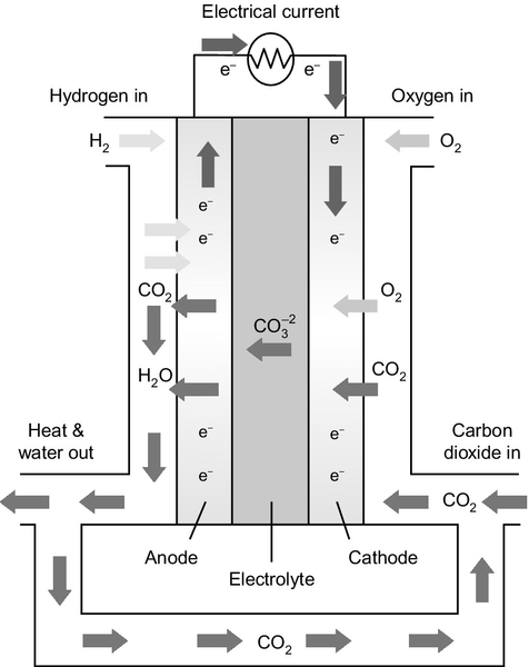
The MCFC has the most complex fuel cell reaction of all the cells available commercially. The electrolyte is a mixture of alkali metal carbonates that, when heated above 650 °C, become molten and capable of conducting carbonate ions (
![]() ). The molten carbonate mixture is held within a solid matrix that is commonly made from lithium aluminum oxide. Hydrogen is fed to the anode of the cell where it reacts with carbonate ions in the electrolyte according to the equation:
). The molten carbonate mixture is held within a solid matrix that is commonly made from lithium aluminum oxide. Hydrogen is fed to the anode of the cell where it reacts with carbonate ions in the electrolyte according to the equation:
![]()
During this reaction part of the electrolyte is consumed and carbon dioxide is released as a gas, mixing with the hydrogen stream. This carbon dioxide is fed back to the cathode where it reacts with oxygen to regenerate carbonate ions in the electrolyte according to the following equation:
![]()
The overall reaction when these two electrode reactions are taken together is simply that of hydrogen and oxygen as in other fuel cells, but it is mediated by the carbonate ions in the electrolyte. Carbon monoxide in the hydrogen fuel can react at the anode to generate more hydrogen in a shift reaction. It can also, in principle, react with carbonate ions and so can form a fuel for the cell.
The high operating temperature of the cell means that the cell reaction takes place without the need for an expensive platinum catalyst and cheaper, nickel-based electrodes are normally employed. The anode is generally a metallic nickel alloy while the cathode is nickel oxide. The latter will dissolve slowly in the hot carbonate electrolyte, which can limit cell life. These electrodes are applied to the outer surfaces of the refractory porous tile in which the electrolyte is held. Cell voltage is 0.8 V.
The reason why such a complex cell has proved worth developing lies in the potential efficiency. The theoretical conversion efficiency is 60% although production units may only achieve around 50%. This does not represent the efficiency limit, however. A MCFC fuel cell produces high-temperature waste heat and this can be exploited in a small gas turbine or a micro-turbine, without the need for additional fuel, to generate more electricity. For greatest efficiency this requires the cell to be pressurized, but in this configuration the MCFC fuel cell may be theoretically capable of between 75% and 80% overall efficiency. Alternatively, the high-grade heat produced by the cell can be used for cogeneration.
The relative complexity of the MCFC means that it is not economical to manufacture and operate very small units. Some of the units that have been developed are over 100 kW in capacity and most are two or three times that size.
The company that dominates the MCFC market is FCE, which was established around 1976 and worked with the U.S. Department of Energy and the U.S. Electric Power Research Institute to develop molten carbonate technology. The company has formed commercial links with companies in Europe and Asia including a partnership with South Korean company POSCO Power. The company’s current range of units includes modules of 300 kW, 1.4 MW, and 2.8 MW, all rated at 47% efficiency.
Applications for the MCFC are generally for large distributed generation. In the United States FCE has developed units that can be run on biogas. It has also developed units that can provide hydrogen as well as electricity by boosting the reforming of natural gas or biogas within the cell.
Other companies that are involved in the development of MCFC units include Italian company Ansaldo and Japanese company Ishikawajima-Harima Heavy Industries. The latter has been working on MCFCs since 1983 and has been involved in government-sponsored development programs. It has tested 300 kW pressurized MCFC stacks operating at a pressure of 4 bars. In South Korea, Doosan Heavy Industries and Construction has also been involved in MCFC development.
Solid Oxide Fuel Cell
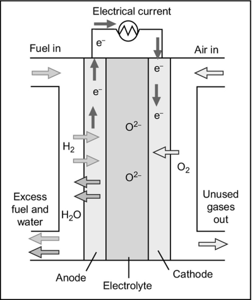
The solid oxide fuel cell (SOFC) is the second major high-temperature fuel cell under development. It is unique among fuel cells for having a solid electrolyte, making it potentially the most robust of all fuel cells (Figure 7.6). The electrolyte is usually made from zirconium oxide, ZrO2, zirconia. When traces of other oxides such as yttrium, calcium, or magnesium oxide are added to the zirconia, it becomes capable of conducting oxygen ions. However, this conductivity only becomes significant at very high temperatures and so the cell must operate at around 1000 °C.
Solid oxide electrolytes were first studied during the 1930s, with little success. However, work continued during the 1950s and 1960s. The most persistent program was carried out by U.S. company Westinghouse (now owned by Siemens) in conjunction with the U.S. Department of Energy. This finally established the SOFC as a viable proposition but that program appears to have halted. However, a range of other companies have since taken up the technology.
As will all the other fuel cells discussed here, the cell reaction in the SOFC involves that between hydrogen and oxygen producing water. The solid oxide that forms the cell electrolyte is an electrical insulator so electrons cannot pass through it. Neither will it conduct hydrogen ions. However, at the cell operating temperature the solid structure will allow oxygen ions, O2 −, to pass. It is this oxygen ion conductivity that permits the fuel cell to operate. In operation, molecular oxygen is delivered to the cathode of the cell where it dissociates and takes up electrons to produce oxygen ions that migrate through the electrolyte to the anode. Hydrogen is delivered to the anode where it too dissociates, releasing electrons to the external circuit and leaving hydrogen ions that react with the migrating oxygen ions to produce water. At the elevated operating temperature this water is produced as vapor that is swept away in the fuel gas stream.
The electrolyte used in the SOFC is very thin. A thickness of around 100 microns is common but they may be as thin as 10 microns. Electrodes must be bonded to the electrolyte layers and these also serve as a support structure to give the cell strength. Since the cell operating temperature is so high, the different materials used in cell construction must be carefully designed to have the same coefficient of expansion, otherwise the cell would crack apart as it was heated.
The solid electrolyte requires an extremely high operating temperature to facilitate oxygen ion conductivity. The most common zirconia-based electrolytes must be heated above 800 °C to ensure they are adequate for cell operation. Newer materials may be able to provide sufficient conductivity at a much lower temperature. However, the temperature needs to remain above around 600 °C to allow reforming of natural gas to take place within the cell.
The high temperature means that no electrode catalyst is necessary to facilitate generation of hydrogen and oxygen atoms at the electrodes. The anode is normally made from metallic nickel dispersed in a ceramic matrix that is unreactive toward hydrogen and the cathode is made from a conductive oxide that will not react with oxygen. Reformation of natural gas into hydrogen can take place directly on the nickel anode.
There are two primary designs for SOFC. The first was developed by Westinghouse and is based on a tubular cell. Under this design the electrolyte/electrode structure is fabricated as a ceramic tube. The cell cathode is on the inside of the tube and the anode on the outside. This creates an extremely practical way of maintaining separation of hydrogen and oxygen fuel streams since these will easily react at the cell operating temperature. However, the fabrication of the tubular structures is expensive.
The alternative is to use a more conventional planar cell design. This is much cheaper to fabricate but makes the fuel gas routing more complex. Most current SOFC designs use planar cells but the use of tubular cells is being resurrected too.
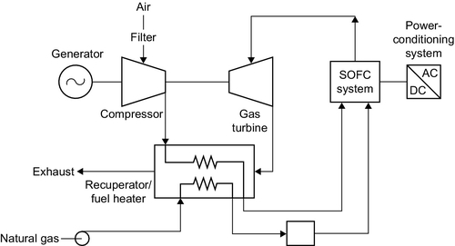
The theoretical efficiency of an SOFC operating around 1000 °C is 60%. Practical cells have achieved around 43% and the practical limit is likely to be around 50%. However, the high operating temperature of the SOFC, coupled with its robust nature, offers a range of hybrid cycle options that can boost output. A simple addition is a heat-recovery steam generator and steam turbine to create a combined cycle plant analogous to that utilized with gas turbines. This could probably boost efficiency to 60% in large systems. More complex but potentially more efficient would be to operate the SOFC under pressure and then use the hot, high-pressure waste gases to drive a gas turbine (Figure 7.7). Heat could then be recovered in a steam generator and used to drive a steam turbine. In a large plant, this configuration could conceivably achieve 73% efficiency though nothing like that level of efficiency has yet been demonstrated.
The major attraction of the SOFC is the robust nature of its electrolyte that is expected to confer extremely long lifetimes. Units have been tested for 60,000 hours without failure and operating lives of 20 years or more are achievable.
Much of the early development of SOFCs was with the aim of producing large units. Stack sizes were expected to be 100 kW to 250 kW and multimegawatt power plants were proposed. More recently the focus has shifted to much smaller units although U.S. company Bloom Energy is offering 100 kW and 200 kW units that have been popular with data centers, often in multimegawatt installations. Meanwhile, units of 1 kW to 10 kW have been developed for the domestic combined heat and power market, particularly in Germany. Other domestic units are being developed for the Japanese market.
Direct Methanol Fuel Cell
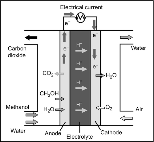
The direct methanol fuel cell (DMFC) is a polymer membrane fuel cell, similar in concept to the PEM fuel cell. The major difference is that in the DMFC the fuel supplied to the anode of the cell is not gaseous hydrogen but methanol in liquid form (Figure 7.8). The methanol, mixed with water, can react directly at the cell electrode without the need for reforming. This simplifies the cell, reducing costs. The use of a liquid rather than a gaseous fuel is extremely attractive too as it makes fuel handling much easier. The main application for the DMFC is as a portable power supply and it is of interest to the automotive industry for the same reason.
Research into the DMFC was carried out in the 1950s and 1960s, then revived during the 1990s. Early cells had exhibited low current densities but this has subsequently been improved. However, efficiency remains poor, with practical cell efficiencies around 25%, low compared to other types of fuel cell. The interest in liquid fuel–based fuel cells has also extended to ethanol and direct ethanol fuel cells are also under development.
The DMFC is novel because its cell reaction combines the reformation of methanol in the presence of water to generate hydrogen at the anode and then the anode reaction of a conventional hydrogen fuel cell. This can be expressed in the two following equations. The first represents the reforming of methanol to generate hydrogen with the production of gaseous carbon dioxide. The second shows the hydrogen atoms that were generated in the first reaction releasing electrons to form hydrogen ions that then migrate through the electrolyte of the cell to the cathode.
![]()
The cathode of the cell is supplied with oxygen from air and the oxygen subsequently reacts at the electrode to generate water. In a stationary application a DMFC will operate at a relatively high temperature up to 130 °C and the water generated at the cathode will simply be swept away with the air as water vapor. For portable applications, however, it is important to try and recover this water and return it to the anode of the cell for recycling through the cell. This will allow the cell to be supplied with pure methanol fuel. Active water recycling systems are relatively complex, adding to the cost of cells, and research is directed at finding passive methods for recycling water between the cell electrodes.
The membrane electrolyte for the DMFC is an acidic polymer membrane similar to that used in a PEM fuel cell, saturated with water. The anode is made from a mixture of platinum and ruthenium deposited onto a carbon support that can then be printed onto the membrane while the cathode is platinum on carbon. One of the problems with the DMFC is diffusion of methanol through the electrolyte from the anode to the cathode where it can react to produce carbon monoxide, which will poison the cathode catalyst.
A DMFC should be able to achieve an efficiency of 40% but practical cells have not exceeded 25%. This may not be a problem for portable applications provided the cell is cheap enough but would probably be too low for larger stationary applications. Cell lifetimes are problematic too with some early cells capable of only 1000 hours.
In spite of these problems DMFCs are beginning to achieve commercial success as power supplies for portable electronic devices such as laptop computers and mobile phones where they can provide a higher energy density and more power from a single charge of methanol than most batteries. Device stacks are typically 200 W or less. Automotive applications are also attractive but the cells have yet to be proven in this application. It is important to note, however, that DMFCs release carbon dioxide during their operation in the same way as a fossil fuel would.
Fuel cell costs
The cost of a fuel cell depends on its application and on the type of fuel cell technology. Fuel cells for automotive applications are expected to be the cheapest available. However, these may have shorter lifetimes than those aimed at large-scale stationary power generation or power and heat generation. Production volumes for the latter are likely to be much smaller too, so the economies of scale achieved from mass production of the former may not be available.
The cheapest fuel cells at the beginning of the second decade of the 21st century are PEM fuel cells for automotive applications, which have a cost of around $50/kW, as shown in Table 7.2. This is based on a U.S. Department of Energy estimate for an 80 kW unit based on a volume production of around half a million each year.
Table 7.2
Fuel Cell Costs
| Fuel Cell Type | Cost ($/kW) |
| Alkaline fuel cell | 9000 |
| Phosphoric acid fuel cell | 4000 |
| PEM fuel cell for automotive applications | 50 |
| PEM fuel cell for domestic applications | 1500–2000 |
| Molten carbonate fuel cell burning natural gas | 4000 |
| Molten carbonate fuel cell burning biogas | 7000 |
| Solid oxide fuel cell for domestic applications | 1500–2000 |
| Solid oxide fuel cell for stationary applications | 7000 |
| Direct methanol fuel cell | Typically around 50,000 for small portable generator |
For stationary applications including domestic heat and power generation and larger-scale power generation the system demands are more stringent and costs higher. Fuel cell stacks in the capacity range of 1–10 kW for domestic systems built from either PEM fuel cells or SOFCs cost around $750/kW, but these units require significant additional equipment and this pushes the unit cost for a complete installation to $1500–2000/kW.
Larger stationary applications, generally for both heat and power, can be met by large PAFC installations or large MCFC installations. For an installation around 1 MW, the cost is likely to be around $4000/kW. SOFC units can also be used for large stationary applications but current costs appear to be higher at $7000/kW. This is similar to the cost of a MCFC designed to burn biogas.
Alkaline fuel cells have generally been considered too expensive for all but niche applications. Representative costs are difficult to find for these units. The most cost effective appears to have a cost around $9000/kW. Most expensive of all, however, are DMFCs. Small units with capacities up to 100 W can be bought for around $5000, or roughly $50,000/kW.