
Solar Power
Abstract
Solar energy is the most important source available to Earth. Solar energy can be exploited directly to generate electricity in two ways. Either the heat from the sun can be concentrated and used to drive a heat engine, or energy can be captured in a solid-state device, a solar cell to provide a source of electric power. Solar thermal power plants come in four main varieties: solar towers, parabolic trough power plants, Fresnel lens plants, and solar dishes, each defined by the method used to concentrate the sun’s heat energy. Solar thermal collection can also be added to a combined cycle gas turbine plant. Solar cells capture light energy directly. These simple solid-state devices are the second-most important new renewable source of electricity after wind power.
Solar energy is the most important source of energy available to the Earth and its inhabitants. Without it there would be no life. It is the energy that drives the photosynthesis reaction. As such, it is responsible for all the biomass on Earth’s surface, which is the source of fossil fuels, the products of photosynthesis millions of years ago that became buried beneath Earth’s surface. Solar energy creates the world’s winds and is, therefore, responsible for wind power; it evaporates the water that is responsible for rain and, therefore, the source of hydropower; even waves and ocean thermal power are both a result of insolation. In fact, apart from nuclear energy, geothermal energy, and tidal power, the sun is wholly or partly responsible for all the forms of energy that are exploited by humans.
While all these different sources of energy, each derived from the sun, can be used to generate electricity, solar energy itself can be used to generate electricity too. This can be achieved most simply by exploiting the heat contained in the sun’s radiation. The use of solar thermal energy has a long history.
Solar thermal power exploitation—that is, the use of the sun as a source of heat—can be traced back at least to Archimedes, but its application as a means to generate power is more recent. Among the early examples were attempts made during the 19th century to use parabolic reflectors to concentrate the sun’s heat energy and raise steam for a steam engine. At the start of the 20th century solar energy was harnessed to drive an engine that pumped irrigation water for agricultural use in Egypt while the first solar thermal power-generating plant was built in Italy in the 1960s. However, the real driving force for the development of solar thermal power generation was the energy crises of the 1970s.
Electricity can also be generated directly from sunlight using an electronic device called the photovoltaic or solar cell. This second route for converting sunlight into electricity can also be traced to the 19th century to the work of the French scientist Antoine-César Becquerel. He was the first to observe the photovoltaic effect during which a voltage is generated when light falls upon an electrode. Following this, the first true solar cell was built at the end of the 19th century by Charles Fritts who coated gold onto selenium to capture light energy. Fritts’ device was very inefficient and it was not until the development of the silicon solar cell by Russell Ohl in 1941 that efficient solar energy collection by this means appeared feasible. This was demonstrated in 1954 when three scientists at Bell Labs in the United States—Gerald Pearson, Calvin Fuller, and Daryl Chapin—produced a cell with an energy conversion efficiency of 6%, and not long afterwards solar cells were adopted as power sources in the U.S. space program.
Today the solar photovoltaic cell or solar cell is rapidly becoming one of the most important sources of renewably generated electricity, and its global installed capacity is third among renewable technologies after hydropower and wind power. Solar thermal power generation has developed less rapidly but it too is beginning to show stronger growth and has the potential to become a major source of power generation later in the century.
Solar energy resource
Solar energy is generated by nuclear reactions within the body of the sun. This energy reaches Earth’s surface in the form of electromagnetic radiation. The composition of this radiation as it travels through space toward Earth is around 56% infrared, 36% visible radiation, and 7% ultraviolet, with the remainder belonging to regions of the electromagnetic spectrum outside the energy ranges covered by these three.
Not all this radiation reaches Earth’s surface. Some is scattered by dust and molecules in the atmosphere. This scattering is a random process, sending the radiation in all directions so that much goes directly back into space. The remainder reaches the surface, but as diffuse, indirect radiation. Clouds act to reflect more sunlight back into space and they play an important role in regulating the temperature of Earth’s surface.
Another part of the radiation is absorbed by molecules such as water, carbon dioxide, ozone, and oxygen within the atmosphere. Water and carbon dioxide absorb energy from the infrared region, whereas oxygen and ozone absorb from the ultraviolet. All these interactions reduce the solar energy flux by around 40% while at the same time changing its composition so that the sunlight that reaches Earth’s surface comprises 50% visible radiation and 47% infrared.
The amount of energy carried by solar radiation is normally expressed in terms of the solar constant that measures the quantity of solar energy passing through one square meter of space perpendicular to the direction of travel of the radiation at the average distance of Earth from the sun. According to the World Energy Council, the value of this constant is 1367 W/m2. When absorption and scattering is taken into account, the total solar flux reaching Earth’s surface is estimated to be 1.08 × 10⁸ GW, and the total reaching Earth’s surface each year is 3,400,000 EJ. This is between 7000 and 8000 times annual global primary energy consumption. If 0.1% of this energy was converted into electricity with 10% efficiency, it would provide four times more generating capacity than the global total of around 5000 GW. See Table 13.1.
Table 13.1
Solar Energy and the Earth
| Solar constant at the distance of Earth from the sun | 1367 W/m2 |
| Total solar energy reaching Earth in a year | 3,400,000 EJ |
| Total solar flux reaching Earth | 1.08 × 10⁸ GW |
| Average solar energy density at Earth’s surface | 170 W/m2 |
Source: World Energy Council.
To put this into a more practical perspective, take the example of a group of solar thermal power plants that were built in California in the late 1980s and early 1990s. These plants were designed on the basis of a solar input of 2725 kWh/m2/y, or 22.75 GWh/y for each hectare. Assuming this energy can be converted with 10% efficiency into electricity, 10 million hectares (100,000 km2) would be sufficient to supply the entire United States.
The solar input is a key parameter when planning a solar thermal power plant. This is determined by the thermal energy density at Earth’s surface, a factor that varies with position on Earth. The average (which takes account of the fact that any point on Earth’s surface only receives sunlight for about half the time, the other half being hours of darkness) is 170 W/m2, while the largest, near the Red Sea, is 300 W/m2. (The latter is just under one-quarter the value of the solar constant.) Over a year, the average incident energy is equivalent to a barrel of oil or 200 kg of coal.
The sunlight that reaches Earth’s surface is of two types: direct radiation and diffuse radiation. The latter is the result of various scattering and absorption processes that take place as the sunlight passes through the atmosphere. Vegetation is able to absorb both types of radiation, and so can solar cells. However, a solar thermal plant requires direct radiation to operate effectively. This limits the applicability of this technology to regions where there is low average annual cloud cover. With no cloud cover, and whatever the location, between 80% and 90% of the sunlight reaching the surface will be direct radiation.
Solar sites and land resources
Since solar energy conversion depends on solar intensity, solar plants are best sited in regions where there is a good level of insolation. For solar thermal plants, the regions of the globe where cloud cover is rare will offer the best locations. These are often the arid, desert regions of the world where land may have little other use. As a consequence of their nature, these regions are often distant from the major demand centers so transmission system extensions are likely to be necessary to exploit them. Some of the areas with good solar thermal potential include the southwestern United States, Rajisthan in India, the Middle East, North Africa, and the southern-most states of the European Union such as Italy, Spain, and Portugal. Typical space requirements for solar thermal plants are 2–5 ha/MW.
Solar photovoltaic power plants are less sensitive to their situation since they do not require direct sunlight and can operate effectively even with cloud cover. As a consequence, they can be used in a wider range of locations. Large, utility-scale, solar cell arrays capable of generating tens or even hundreds of megawatts of power are becoming popular, but most of the global capacity today is derived from rooftop-mounted solar cells. These units often supply power locally and collectively they represent one of the largest forms of distributed generation in operation. Space demands for both rooftop and utility arrays of solar cells are similar, but rooftop deployment allows cells to exploit otherwise unused space. Utility arrays demand a similar area of land to solar thermal power plants.
Solar power generation technologies
As already outlined, there are two ways of turning the energy contained in sunlight into electricity. The first, called solar thermal power generation, involves using the sun simply as a source of heat. This heat is captured, concentrated, and used to drive a heat engine. The heat engine may be a conventional steam turbine, in which case the heat will be used to generate steam, but it could also be a closed-cycle turbine system using an organic thermodynamic fluid, a gas turbine, or a Sterling engine.
The second way of capturing solar energy and converting it into electricity involves use of the photovoltaic or solar cell. The solar cell is a solid-state device like a transistor or microchip. It uses the physical characteristics of a semiconductor such as silicon to turn the sunlight directly into electricity. The simplicity and durability of the solar cell makes it an extremely attractive method of generating electrical power.
As with several other renewable technologies, solar energy is intermittent; it is only available during hours of daylight. In many parts of the world where there is a good solar resource, high levels of sunlight often coincide with a peak in demand for air conditioning, so solar power, particularly in the form of rooftop solar panels, can provide synchronized peak power. In addition, some solar thermal power plants can incorporate thermal energy storage, which will allow them to operate round-the-clock, depending on the size of the energy store. Otherwise, solar power is generated when the sun shines and must be fed into the grid immediately. This means that under normal circumstances, the solar power must be dispatched when it is available, while other generating plants must be ready to provide an alternative source of power when solar power is not available.
Solar thermal power generation
Solar thermal power generation uses the sun simply as a source of heat. As discussed before, the energy reaching Earth’s surface is mostly either infrared or visible radiation. A solar thermal plant can utilize the infrared and a small part of the visible spectrum. This energy is absorbed and used to raise the temperature of a heat-transfer fluid while the remainder is rejected.
The solar radiation as it reaches Earth is of relatively low intensity and it must be concentrated to be an effective source of heat. In solar thermal power plants this is carried out by the use of mirrors with the type of mirror defining the solar thermal power plant. Three types are in common use: a parabolic trough reflector, solar tower power plant, and parabolic dish solar power plant. A fourth type uses a Fresnel lens that approximates to a parabolic trough reflector.
There are two other types of solar thermal power plant. One is a solar pond, a large area of water exposed to sunlight that is designed to maintain a small temperature gradient between its upper and lower layers that can be used to drive a heat engine. This is a relatively low-technology solar thermal plant and it has been rarely used. The second, called a solar chimney, has only been tested at very small scale and never deployed commercially. The idea behind it is to exploit the heating of air by the sun to generate an updraft in a very tall chimney. Wind turbines are then placed within the chimney and their rotation generates electricity.
Parabolic Troughs
The sunlight that reaches Earth, while it can feel extremely hot, does not contain sufficient energy in the diffuse form in which it arrives to constitute the basis for a thermal power generation system. To make it useful, the sunlight from a large area must be concentrated. This can be achieved with a magnifying lens, but lenses form a relatively expensive way of concentrating sunlight. Much better is a concentrating reflector.
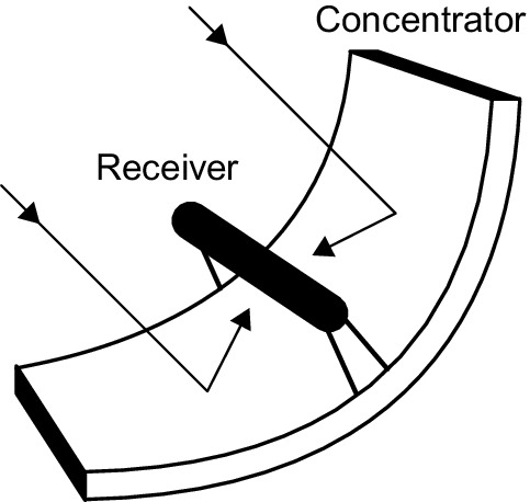
The parabola is the ideal shape for a solar reflector because it concentrates all the light incident on it from the sun at a single point called the focus. A complete parabola is circular; this forms the basis for a solar dish system (see later). However, there is a limit to the size of dish that can be built. For large-scale solar concentration, a trough-shaped reflector has proved more effective. If the trough is built with a parabolic cross-section, the reflector will bring the incident sunlight to focus at a line rather than at a single point—that is, a line running along the length of the trough (Figure 13.1). A heat absorption system is then placed along the length of the trough at its focus. This is the basis for the solar trough, sometimes called a line-focusing solar thermal power plant.
Parabolic troughs are the oldest solar thermal technology and were first used for a plant built near Cairo in 1912 to generate steam that drove a steam engine pump. The earliest modern electricity-generating plants of this type were built in California in the 1980s and early 1990s, and nine plants are still operating. However, the economics of solar thermal technology were marginal at that time and it was not until the first decade of this century that further plants of were built.
The key element of a parabolic trough solar plant is the reflecting trough itself. These have traditionally been manufactured from 4 mm glass that is hot-formed into the required parabolic shape in a special bending plant and then mirrored. A typical trough will be up to 5–6 m wide (this is called its aperture) and will be made from individual sections up to 20 m in length that are used to build troughs up to 150 m in length. These are then mounted onto a tubular steel frame and fitted with a tracking system that enables them to track the sun across the sky. The long axis of each trough is aligned north to south so that they can rotate to track the sun from east to west. A typical 50 MW parabolic trough solar thermal plant will have 600 individual troughs and a total reflector area of around 500,000 m2.
The cost of the reflector is the single-most important capital cost element of a parabolic trough plant, so ways of reducing costs are attracting attention. Some developers are using polymer troughs that are cheaper than glass, and lighter, but their reflection efficiency and durability are not generally as good as that of glass. Aluminum-alloy mirrors have also been used.
The heat concentrated in the parabolic trough is collected using a pipe running along the length of each mirror, at its focus, and containing a heat-transfer fluid that is pumped along the pipe. This pipe will generally be made from steel to which a special coating has been applied to maximize the heat absorption. A single heat collection pipe will run through several 150 m long mirrors to enable the heat-transfer fluid to reach a high enough temperature for power generation. These individual heat-transfer pipes are then connected in parallel in the heat collection circuit.
A parabolic reflector can concentrate sunlight between 60 and 100 times (the concentration ratio) and this is capable of raising the temperature of the heat-transfer fluid to a much as 550 °C. However, the actual temperature is often limited by the heat-transfer fluid, usually synthetic oil, which must be kept below 400° to prevent it from decomposing. For a typical plant of this type the heat-transfer fluid enters the solar field at 290 °C and leaves at 390 °C.
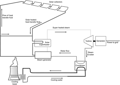
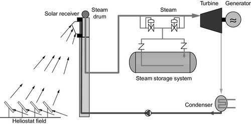
To generate electricity from sunlight, the heat contained within the heat-transfer fluid is used to raise steam to drive a steam turbine (Figure 13.2). This is carried out by passing it through a series of heat exchangers. Modern plants often use a reheat steam turbine that has two turbine sections with the steam heated again when it exits the first section and before entering the second section. This is usually more efficient than using a single-stage turbine. A recent 50 MW plant in Spain used a 50 MW reheat steam turbine with steam conditions of 370 °C and 100 bar.
Some plants also use supplementary heating provided by natural gas to both improve their reliability during variable sunlight conditions and to extend the range of operation into the early morning and late evening. Sunlight collection efficiency is around 75% but the low temperature of the heat-transfer fluid makes the turbine cycle relatively inefficient, at around 38%. Overall efficiency is generally 15–16%.
The operation of a parabolic trough plant can be improved by adding a heat storage facility. With this, the plant can operate for longer each day. It is not considered efficient to store the heat-transfer fluid itself, so plants that adopt this configuration usually use an alternative heat storage medium. The most common is molten salt, usually a mixture of nitrates, that can operate up to 600 °C.
A heat storage system comprises two tanks, one containing hot heat storage fluid and the other cold fluid (or relatively cold, for it will still be at around 300 °C to maintain it in the liquid state). To store energy, molten salt is taken from the colder tank and heated using the heat-transfer fluid then stored in the hot tank. To extract energy again the cycle is reversed with salt from the hot tank used to raise steam for power generation before being returned to the cold tank. With storage, the capacity factor of a solar thermal plant of this type can be raised from around 20–30% to 60%.
The amount of energy that can be stored will depend on the generating capacity of the plant and the size of the solar field. The larger the solar field relative to the size of the plant turbine, the more energy can be stored. However, since the solar field is the single-most expensive part of the plant, the economics of storage need to be weighed carefully. In principle, a plant could be designed to operate 24 hours each day, but generally they are designed to be capable of supplying power during the main periods of grid demand rather than continuously.
Since 2007 a number of commercial solar trough power plants have been built. The largest concentration of these is in Spain. Many of these installations are around 50 MW in generating capacity and a number include some form of energy storage. Larger-capacity plants have been proposed, particularly in the United States, but these have not yet been built.
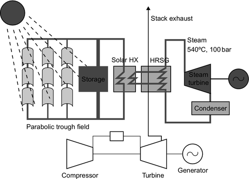
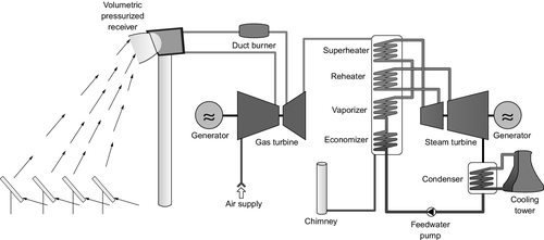
In addition to the standard parabolic trough plant it is possible to build a hybrid solar fossil fuel power plant using trough technology (Figure 13.3). Such plants are based on a natural gas–fired combined cycle power plant but with an additional solar collection field. In this type of plant natural gas is burned in the gas turbine to generate power and then the exhaust gases are fed into a heat-recovery steam generator to provide steam, but with the steam production boosted during sunlight hours by heat from the solar field. These plants are normally called integrated solar combined cycle or ISCC plants. Many of the ISCC plants that have been constructed are in North Africa or the Middle East where both cheap natural gas and abundant sunlight are available, but the configuration can be exploited in many parts of the world.
Although most parabolic trough power plants use a synthetic oil as the heat-transfer fluid, the efficiency of the plants could be increased by using a direct-steam cycle. This would involve doing away with the heat-transfer fluid and heating water to generate steam directly within the parabolic trough heat collection and transfer circuit. While this presents some engineering problems, it would allow much higher steam operating conditions to be achieved, leading to higher heat engine efficiency. Direct-steam technology is being actively developed by several companies and research organizations. Another area that could add to performance would be the use of concrete for energy storage. Concrete would offer a much cheaper option than molten salt because it can store heat at a higher temperature, allowing smaller stores to be built as well as enabling a higher thermodynamic efficiency to be achieved.
Solar Towers
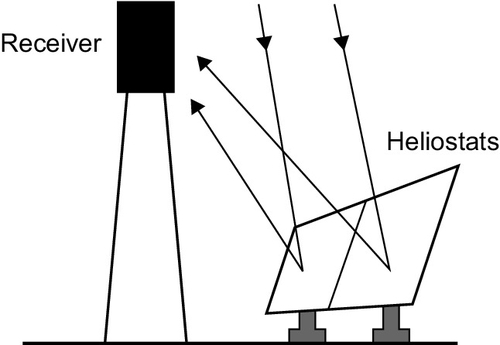
The solar tower takes a slightly different approach to solar thermal power generation. Whereas the parabolic trough array uses a heat collection system spread throughout the solar array, the solar tower concentrates heat collection at a single central facility. The central facility includes a large solar energy receiver and heat collector that is fitted to the top of a tower. The tower is positioned in the center of a field of special mirrors called heliostats, each of which is controlled to focus the sunlight that reaches it onto the tower-mounted solar receiver. This type of solar thermal plant is referred to as a point-focusing solar thermal plant (Figure 13.4).
The earliest solar tower was a 500 kW test rig constructed in Spain in 1981. It used liquid sodium as its heat-transfer medium (similar to some types of experimental nuclear reactor). In 1982 a project called Solar 1 was built at Barstow in California with a generating capacity of 10 MW based on a water/steam heat-transfer cycle. Solar 1 was upgraded to Solar 2 in 1996 and used molten salt to absorb and transfer the heat. Tests were carried out elsewhere too, but it was not until 2007 that the first commercial solar tower project, called Planta Solar 10 (PS10), began operating in Spain. The technology remains less well developed than solar trough technology.
The solar tower power plant is essentially an approximation of a massive parabolic dish, with a typical layout shown in Figure 13.5. The mirrors that make up its solar field are all parabolic reflectors that concentrate sunlight to a focus at the top of the central tower. However, each ring of reflectors belongs to a parabola of slightly different size. Each mirror must be able to track the sun independently, making the solar collection system relatively more expensive than for a solar trough plant. The advantage is that a higher temperature can be achieved in this type of plant. A concentration factor between 600 times and 1000 times is possible, allowing temperatures between 800 °C and 1000 °C to be reached. Existing plants have only achieved 600 °C, but even so this provides a 20% increase in efficiency in the steam cycle over a solar trough plant using a synthetic-oil heat-transfer fluid.
The maximum size of a solar tower power plant is determined by the size of the solar field that can be built. This will be limited because once the distance from the heliostat to the central receiver becomes too large, efficiency will drop. It appears likely that the largest single field tower will be around 200 MW or less. Larger plants will have to be based on multiple fields and towers.
The mirrors, or heliostats, used in a solar tower field are almost flat and this helps make them cheaper to manufacture than solar troughs. The nature of the solar tower means that flat terrain is not necessary either to build the plant. For a solar trough plant a flat site is essential. Heliostats are typically up to 120 m2 in area. The 11 MW PS10 plant in Spain has 624, occupying an area of 60 ha or 5.5 ha/MW. A second Spanish plant, PS20 with 20 MW capacity, has 1255 heliostats covering an area of 90 ha.
Both or these Spanish solar towers use a direct-steam system to capture heat and generate steam. The steam conditions are relatively low at 250 °C and 40 bar and this limits the overall efficiency of the plants. Steam storage tanks are also used to extend the operating range of each plant but this is only suitable for short-term storage and operation is limited to the hours of sunlight.
An alternative approach is to use a molten salt as the heat absorption and transfer fluid. This was the approach used in the demonstration Solar 2 project in California during the 1990s. Such an approach also lends itself to heat storage since the molten salt can be stored hot in a cycle similar to that outlined earlier for heat storage with a parabolic trough plant. Hot salt is then taken from the storage tank and passed through heat exchangers to generate steam before being stored again in the cold tank. Though more expensive than a direct-steam plant, the molten salt storage system allows the plant to operate for much longer because of its higher storage capability.
There is a third design for a solar tower that could potentially offer even better performance by using air as the heat-transfer fluid. This is the basis of the volumetric air receiver, built from ceramics and capable of heating air to 1000 °C (Figure 13.6). In the simplest air system, the air is passed through heat exchangers and used to generate steam to drive a turbine. However, a more advanced cycle uses pressurized air that can be used to drive a gas turbine, once heated. The hot air exiting the gas turbine is then used to generate steam for a steam turbine in a cycle similar to the combined cycle power plant. An air cycle is not easily adapted for energy storage but can be fitted with supplementary natural gas firing if necessary.
Spain is the location for the largest solar towers in operation today. These include the PS20 20 MW plant and the Gemasolar plant with a generating capacity of 19.9 MW. The latter, which began operating in 2011, uses a molten-salt heat-transfer fluid and is sized so that it can provide power for up to 15 hours each day without the need for sunlight. This allows it to claim 24-hour operation. Overall plant efficiency is estimated to be 15% and the plant has a capacity factor of 65%. A much larger project is under construction at Ivanpah in California. This plant will comprise three facilities with a combined generating capacity of 377 MW. Each facility will have several towers, with the individual tower size expected to be 33––50 MW. These are based on a direct-steam cycle with steam conditions of 550 °C and 160 bar. The first unit started delivering power to the grid in 2013 from the first of three towers. These plants require 3.4 ha/MW.
Solar Dishes
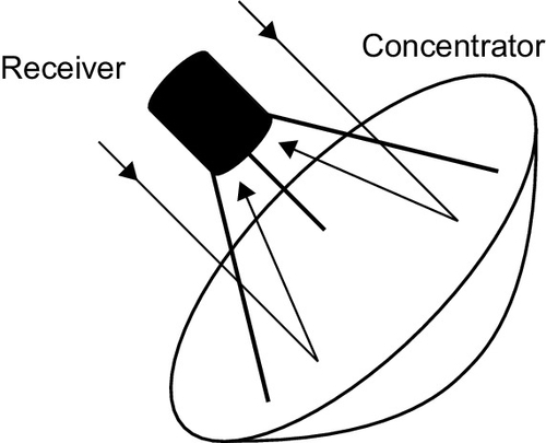
A solar dish power plant is typically a single parabolic reflector similar to a satellite antenna but with a heat engine instead of a microwave receiver at its focus (Figure 13.7). The dish and its engine are constructed as a single unit, mounted on a framework that will allow it to track the sun across the sky. Most solar dish power units are 25 kW or less though bigger ones have been built. Deployed singly, they can provide a self-contained power supply unit. However, they can also be deployed in larger numbers to provide higher generating capacity.
Most solar dishes use simple self-contained heat engines to generate power, but in one or two recent projects solar dish systems have been designed to provide steam for a steam turbine. The main advantages of solar dishes are their simplicity and efficiency. Single solar dishes are capable of achieving 30% energy conversion efficiency, much higher than any of the other solar thermal technologies.
The first solar dish energy devices were built by the French mathematician August Mouchet in the 19th century to drive a steam engine. The modern version, designed for power generation, began to appear after the 1970’s energy crises. However, the technology has struggled to prove itself economically and it was only at the end of the first decade of the 21st century that a demonstration project involving a large array of solar dishes finally started generating power.
The solar dish can be considered to be a solar tower in miniature, a point focusing solar thermal system with a high concentration ratio. With its single, continuous reflector a solar dish can achieve a concentration ratio of 2000. This allows a very high temperature up to 1000 °C to be achieved, allowing high energy conversion efficiency. The heat engine at the center of a dish is matched to the heat input, with a 10 m diameter dish capable of supplying around 25 kW of electrical power with a direct solar insolation of 1000 W/m2. Units capable of providing up to 100 kW have been built, but at larger sizes the dishes become massive and difficult to manage.
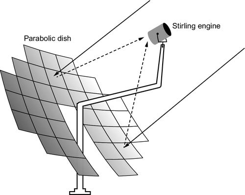
As with other types of solar thermal power plants the reflectors for solar dishes are generally made from mirrored glass (Figure 13.8). However, a single 10 m diameter glass reflector would be prohibitively expensive (and heavy) so they are usually made up from an array of small elements that approximate the large dish. Plastic and aluminum reflectors have also been tested, as well as a novel technique in which a thin plastic membrane is pulled taut over a hoop and then deformed by applying a partial vacuum to one side of it.
To achieve high efficiency, a solar dish must track the sun accurately. For larger dishes this is usually achieved by tracking on two perpendicular axes. For smaller dishes polar tracking is often deployed. This involves rotating the dish about an axis parallel to Earth’s axis of rotation at 15°/hour to match the speed Earth’s rotation. Movement about a second axis is often used to take account of the seasonal movement of the sun in the sky.
The generation of electricity with a solar dish is normally carried out with a small self-contained engine, usually either a Stirling engine or a micro-turbine fixed at its focus. In both cases the heat at the focus of the dish is used to heat a thermodynamic fluid that drives the engine, generating power. In a Stirling engine that fluid is hydrogen or helium held within the engine in a closed cycle. With a micro-turbine the thermodynamic fluid is air and the cycle is that of a gas turbine cycle. The Stirling engine is capable of very high efficiency and, although operating engines in solar dishes have only achieved just over 31% efficiency, 40% may be feasible. The micro-turbine is less efficient, with a potential efficiency around 30%, but they are cheaper. In addition, the heat input into the micro-turbine can be boosted with natural gas if necessary. That is less easy to achieve with the Stirling engine, which has a completely closed cycle.
It is possible to build a solar dish that can use the heat it collects to generate steam for a steam turbine. To make this effective it will normally be necessary either to construct one very large dish or build a series of smaller dishes connected to a single heat circuit. Dish systems based on a steam cycle have been developed by the Australian National University.
The commercialization of solar dish technology has been slow. The first semi-commercial project, the Maricopa power plant in Phoenix, Arizona, entered service in 2010. The plant has 60 parabolic dishes with an aggregate generating capacity of 1.5 MW. Its construction was supported by the U.S. government. A project of similar capacity at the Tooele Army Base in Utah began testing in the middle of 2013. Much larger schemes have been proposed in California.
Fresnel Reflectors
The Fresnel reflector represents an attempt to reduce the cost of solar thermal technology by creating a cheap heat collection system. In this case the model is the parabolic trough. However, instead of a single parabolic trough, the Fresnel system employs a series of long, almost flat reflectors that approximate the trough. Each individual reflector is mounted so that it can track the sun and the energy it collects is focused onto a stationary pipe above the reflectors running the length of the trough. Figure 13.9 provides a typical layout.
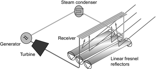
The earliest solar thermal plant based on Fresnel reflectors was developed by an Italian, Giovanni Francia, who patented the system in 1962 and built a prototype in France in 1964. Further development took place in Australia in the 1990s where a large demonstration scheme was constructed, and since then plants have been built in the United States and in southern Spain.
The Fresnel system bears some similarity to the solar tower approach with a series of flat reflectors approximating the parabolic reflector, although in this case the reflector it mimics is a trough. Like the tower, these reflectors can be mounted close to the ground, simplifying construction and increasing stability while the reflector and heat collector are separated, making the design simpler. The reflectors are long and either flat or slightly curved, with around 20 replacing a single trough. As with a trough, each reflector is made of around six individual segments. They are usually made from glass but other materials are possible. Collection efficiency is lower than for a parabolic trough, with a concentration ratio of between 30 and 50 typical.
Fresnel power plants usually use direct-steam generation to improve efficiency and reduce costs. They are claimed to have smaller space requirements than traditional trough plants with around 1.3 ha/MW. One of the largest operating plants is the Augustin Fresnel 1 plant in France with a generating capacity of 250 MW. This plant uses water as the heat-transfer fluid, the latter exiting the heat collection field at 300 °C. The turbine operating pressure is 100 bar. The plant began generating power for the grid in 2012.
Other Solar Thermal Technologies
The solar chimney (sometimes confusing since also called a solar tower) uses heat from the sun to raise the temperature of an enclosed volume of air, creating a pressure that can be used to produce an updraft in a tall chimney. Turbines within the chimney can then generate electricity.
To make this feasible, a large circular greenhouse must be constructed to capture heat and raise the temperature of the air enclosed within it, as shown in Figure 13.10. The outer edges of the greenhouse are open so that air can be drawn in. Meanwhile, at the center of the circle rises a tall chimney. The hot air within the greenhouse is drawn toward and up this chimney, creating an air flow that can be exploited by wind turbines to produce electricity.
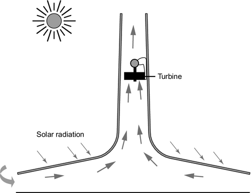
Although the idea for a solar tower was published as early as 1903 by a Spaniard, Isidoro Cabanyes, the first to be built was constructed in 1981 in southern Spain by a German company. This had a 180 m high, 12 m diameter tower and housed a single 50 kW turbine to test to principle. The project operated until 1989. The concept has since been adopted by a U.S. company that has put forward plans to build a major plant of 100–200 MW but no plant has yet been constructed. In 2010 a 200 kW tower started operating in Inner Mongolia. There are plans to expand this Chinese development to around 27 MW.
A solar pond is also a relatively old idea that has rarely been exploited. It consists of a shallow pond, usually between one and two meters in depth, filled with brine and covered with some form of membrane to prevent evaporation (Figure 13.11). When sunlight heats the brine it creates a layer of hot, concentrated brine at the bottom of the pond. As a consequence of its density the brine remains at the bottom of the pond even though it is hotter than the water above it.
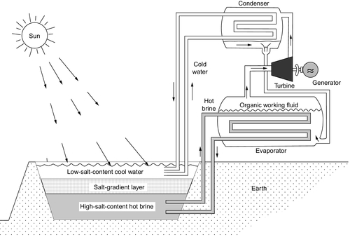
The hot brine can reach 70–80 °C while the upper layer will be between 20 °C and 30 °C, creating a temperature gradient that can be used to drive a small heat engine. This is usually a small organic Rankine cycle turbine that can extract energy from such a tiny temperature difference. The technology was tested in Israel during the 1980s when a 5 MW project was built in the Dead Sea region, but it does not appear to have been pursued, either there or elsewhere.
Photovoltaic devices
Photovoltaic devices, often called solar cells, are solid-state devices that are capable of absorbing sunlight and converting it into an electrical current. The earliest observation of the photovoltaic effect was by the French scientist Antoine-César Becquerel but the practical solar cell was developed by scientists at Bell Laboratories in the United States in the 1940s and 1950s. These cells were around 6% efficient and during the 1960s they were used in the U.S. space program. As costs came down they began to be used in the 1980s for remote terrestrial applications and during the 1990s, with prices continuing to fall, grid-connected solar cells began to appear. Their use expanded dramatically from the end of the 1990s, and by the beginning of the second decade of the 21st century they had become the third most important source of renewable electricity after hydropower and wind power. Their simplicity, combined with continued lowering costs, means that they could overtake wind power in the next decade or two.
Solar Photovoltaic Technology
The operation of a solar cell depends on a fundamental property of a semiconductor called its bandwidth. The bandwidth is a function of the semiconductor’s atomic structure that results in an energy gap between the top layer of full electron energy levels and the first set of empty energy levels. The energy gap is too large for electrons to jump from the lower to the upper as a result of thermal activation. However, electrons in the lower level can become promoted from the lower to the upper level, across the bandwidth, by absorbing photons of electromagnetic radiation. For this to be possible, the photon must contain at least as much energy as the size of the energy gap between the two sets of energy levels in the semiconductor.
The range of electromagnetic radiation that the cell can absorb is determined by the size of its bandwidth. Semiconductors that are useful for solar cells have bandwidths that make them capable of absorbing photons within the visible region of the solar spectrum, but any photon with an energy lower than the bandwidth (e.g., infrared radiation) will not be absorbed. However, all those with energy greater than the bandwidth can be absorbed. Table 13.2 shows the bandwidths of some semiconductors that are commonly used for solar cells.
Table 13.2
Bandwidth of Some Common Solar Cell Semiconductors
| Semiconductor | Bandwidth (eV) |
| Silicon | 1.11 |
| Cadmium telluride | 1.44 |
| Gallium arsenide | 1.43 |
| Copper indium gallium diselenide | 0.9–1.7 |
Each photon of light energy that is absorbed by the semiconductor is captured by an electron within the material. In absorbing the energy, the electron acquires an electrical potential (it has more energy than most of those around it). This potential can be made available as electrical energy, as an electric current. The current is produced at a specific fixed voltage called the cell voltage. The cell voltage is, again, a property of the semi-conducting material. For silicon it is around 0.6 V.
The energy contained in light increases as the frequency increases from infrared through red to blue and ultraviolet light. However, a solar cell must throw away some of these frequencies since it can only absorb light above its cell threshold. Light that is of an energy below this threshold simply passes through the material.
It might seem sensible, therefore, to use a semiconductor with a low threshold or bandwidth. However, this will lead to a cell with a low output voltage since this is also directly related to the threshold for absorption. There is another drawback to using a semiconductor with a small bandwidth. When a photon of light with energy much greater than the threshold energy is absorbed, it loses all the energy above the threshold value. The surplus energy is essentially thrown away (it emerges as heat) and cannot be used for electricity production.
These two factors mean that the lower the bandwidth and absorption threshold, the more energy is thrown away as heat, but the higher the bandwidth, the more energy simply passes through the material without being absorbed. The optimum is, therefore, a compromise between the two competing effects.
The optimum bandwidth for a solar cell semiconductor is 1.43 eV. The bandwidth of silicon, at 1.11 eV, is below the optimum but it has proved the most effective solar cell material to date and has the largest market share. Silicon is used in three different forms: crystalline, semi-crystalline, and amorphous. Crystalline silicon is the most efficient but also the most expensive to produce, while amorphous silicon is both the least efficient and the cheapest. Alternatives to silicon include cadmium telluride, which is cheaper to produce and is always in amorphous form. Its bandwidth is very close to the optimum. Other materials such as gallium arsenide are also more efficient that silicon, particularly in crystalline form, but are much more expensive.
Types of Solar Cell
Solar cells are manufactured using technologies similar to those used to manufacture microchips and transistors. Most of these are made using slices of perfect silicon crystals that are then etched and doped to create the complex structures that are required for computers and other electronic devices. Solar cells, though normally simpler in structure than a microchip, can be manufactured in a similar way.
Silicon solar cells made from single crystal silicon are the most efficient available with reliable commercial cell efficiencies up to 20% and laboratory efficiencies measured at 24%. Even though this is the most expensive form of silicon it remains the most popular by a wide margin due to its high efficiency and durability. Polycrystalline silicon is cheaper to manufacture but the penalty is lower efficiency with the best measured around 18%. Cheapest of all to produce is amorphous silicon, which can be made using vapor deposition techniques rather than by expensive crystal growing. However, its best efficiency is only 8%. Amorphous silicon also suffers from degradation when first exposed to light, a feature not seen with crystalline material. This can reduce its initial efficiency by up to 20%.
All silicon solar cells require extremely pure silicon. The manufacture of pure silicon is both expensive and energy intensive. The traditional method of production required 90 kWh of electricity for each kilogram of silicon. Newer methods have been able to reduce this to 15 kWh per kilogram. This still means that depending on its efficiency, a silicon solar cell can take up to two years to generate the energy needed to make it. This compares with around five months for a solar thermal power plant. Manufacturers of crystalline silicon are concentrating on ways of reducing the cost of crystalline material by cutting it more efficiently or by finding new ways of growing it. This is helping push costs down, and crystalline silicon remains competitive in spite of efforts by thin film manufacturers using much cheaper materials.
Another crystalline material used for solar cells is gallium arsenide. This has an almost perfect bandwidth for a solar cell and in the laboratory efficiencies of 28% have been recorded. However, practical cells only reach 20% and the material is both expensive and composed of hazardous materials. It is rarely used, except for special applications.
The main alternative to crystalline silicon for solar cells is some form of thin film. From a manufacturing point of view these are attractive because they can be produced using cheap techniques such as vapor deposition or even printing. Amorphous silicon is one alternative but it is not as cheap to produce as cadmium telluride and the latter has a much higher efficiency, with the best recorded at 17% though commercial cells rarely achieve more than 11%. This material also has an almost optimum bandwidth for a solar cell (1.44 eV) and its potential efficiency could approach 30%. Cadmium telluride is also attractive because it is possible to produce solar cells on a variety of substrates including building components and flexible plastic sheets.
The maximum efficiency possible with a single-layer solar cell of any semiconductor is 33.7%. It is possible to build more efficient solar cells by layering cells one on top of the other. Such multilayer or multijunction cells place the semiconductor with the largest bandwidth at the top. This will absorb high-energy radiation but that of lower energy will pass through it to reach the layers below where further semiconductor layers of lower bandwidth are placed. In principle, it is possible to create a cell with up to 50% energy efficiency with multilayer cells, but they are much more expensive to manufacture. The best recorded efficiency achieved to date is 43.7%.
Cell Structures
The conventional structure for a solar cell is planar (Figure 13.12). The cell is made of a thin layer of semiconductor, the top surface of which is doped with an impurity to create a p-n junction within the body of the material. It is this junction, with a built-in voltage gradient, that captures electrons once they are generated by light absorption and sweeps them away to form an electric current. To collect the current, electrical contacts must be formed onto the semiconductor. The rear of the cell can be covered with a planar collector, but on the front surface, where light is absorbed, the collector area must be minimized or it will interfere with light absorption. The front collector is usually made from narrow fingers of metal that allow the maximum amount of sunlight to strike the semiconductor surface. The semiconductor will often be placed on a substrate to give it additional strength and the top layer will be covered with a protective coating.
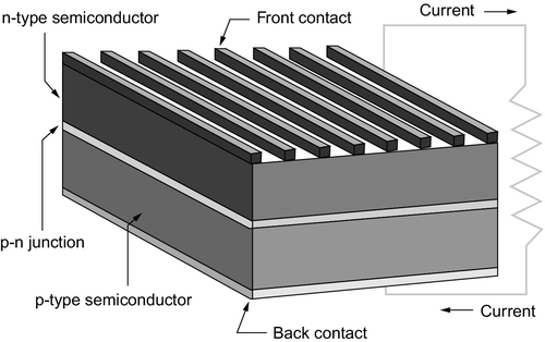
More advanced structures are possible. The front contacts can be buried, edgeways, into the surface of the cell to minimize the shadow effect of the contact that reduces efficiency. More modern cells have also been developed that move both contacts to the back of the cell by allowing the front doping to be carried to the back of the semiconductor. This structure is more complex but creates a more efficient cell.
Efficiency depends on light absorption. This can be improved by making the front surface of the cell nonreflecting and by making the back reflective so that any light reaching the back layer is reflected back into the semiconductor. Such developments mean that the number of stages in the fabrication of a solar cell can increase to perhaps 15 from a more usual 6–8. However, the lowering of production costs and the increased efficiency are making such developments worthwhile.
Such advanced techniques are generally only used with crystalline silicon. Amorphous or thin-film devices rely on cheaper fabrication techniques for their economics. Cadmium telluride, the most popular thin-film material, is usually formed on a substrate such as glass. However, it can also be deposited onto flexible plastics. These thin films can be produced in much larger areas than crystalline silicon, which helps make them more cost effective. Copper-indium-gallium-diselenide is another thin-film solar cell material. This has the advantage that by varying its composition, the bandwidth can be varied, which offers the potential to tailor cells to particular applications or to manufacture complex multilayer cells with specific characteristics.
Concentrating Solar Cells
Concentrating solar cells adopt a different strategy to planar cells. Whereas the latter capture sunlight over a large area of semiconductor, concentrating cells use cheap optical systems to concentrate the sunlight first, in a manner similar to most solar thermal technologies, before converting it into electricity. In principle, an optical system can be manufactured more cheaply than a large area planar solar cell. The device can then use a very expensive, but highly efficient,multijunction solar cell at the focus to convert the light into electricity. As noted before, this type of solar converter has achieved the highest efficiency of any solar cell at 43.7%.
The disadvantage of the concentrating cell is that it requires direct sunlight and cannot operate effectively with diffuse sunlight. While these converters have a limited market share today, there are signs that they may be attractive for utility-scale applications in high insolation regions where their high efficiency is likely to be an advantage.
Third-generation Solar Cells
In the market for solar cells, crystalline silicon cells are often referred to as first-generation solar cells and thin-film devices as second-generation cells. Third-generation cells are new organic and dye-sensitized solar cells.
Organic semiconductors operate in exactly the same way as conventional ones, but with the disadvantage that the organic material does not conduct electricity as readily as a traditional semiconducting material. The key to developing organic materials is to find an efficient way of extracting the electrical power once it has been generated. (If the excited electrons are not swept away quickly, they will simply fall back to the lower energy level in the semiconductor and lose their energy.) While this can be a drawback, the attraction of organic materials is the simplicity of their production. It is expected to be possible to print the semiconductor onto substrates, making it extremely flexible in the way it can be used. However, efficiencies of organic semiconductors are currently very low with the best laboratory value of 6% and the best production efficiency of 4%.
Dye-sensitized solar cells use special dyes to absorb light and then transfer the electron produced during the absorption to a substrate semiconducting material. These devices have been compared to photosynthesis, but the complex series of exchanges required to make them work also makes them appear similar to electrochemical devices such as batteries. As with organic semiconductors these are attractive because of the simplicity of manufacture as they too can be printed. Theoretical maximum efficiency is 31% and practical efficiencies of 13% have been achieved. Both types can maintain their outputs under low light conditions but long-term stability is still questionable.
Modules, Inverters, and Panels
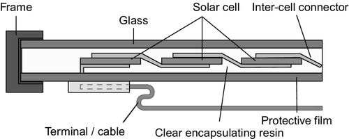
Most solar photovoltaic energy conversion is based on planar solar cells but the actual solar cells account for only a part of the complete system required to create a solar energy conversion installation. Individual silicon solar cells only produce one of two watts of electricity each at, for a silicon cell, 0.6 V. Therefore, cells must be connected in series and in parallel to create modules capable of both higher power and of generating at a higher voltage (Figure 13.13). These modules must then be encapsulated to protect them from the environment. An encapsulated module of this type is called a solar panel and it may have an output of several watts to several hundred watts. Current encapsulation techniques are capable of providing modules with lifetimes of 25–30 years. Advanced encapsulation techniques may be able to extend this to perhaps 50 years of more in the near future.
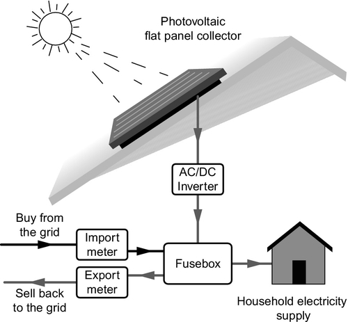
The output of the solar panel is direct current. This can be used without conditioning in some remote applications, but for grid connection the DC must be converted into alternating current at the grid voltage. This is carried out using a solid-state inverter. Modern inverters, particularly for larger solar panel installations, are sophisticated devices that can provide two-way communication with transmission and distribution system operators. Other parts of the complete installation include the supports, typically of steel. For a modern solar photovoltaic installation the solar cell probably accounts for 50–60% of the total cost, but this is falling as fabrication costs fall.
System Types
There are broadly four types of solar photovoltaic installation, each serving a different market sector. The most important of these today is the residential sector that includes installations up to 20 kW on domestic rooftops (Figure 13.14). This is the sector that has been the focus of incentive schemes in countries such as Japan, Germany, the United Kingdom, Italy, and the United States, and it accounts for by far the largest installed capacity of solar cells, worldwide.
Allied to this is the commercial sector. This covers larger building installations at schools, hospitals, office buildings, shopping centers, and other similar organizational buildings. Installations for these types of buildings may be up to 1 MW in generating capacity.
The utility sector is the third major market sector. This involves large arrays feeding power directly into the grid. Plants of this type have capacities between 1 MW and 200 MW and larger installations are likely in the future. This is developing into one of the main markets for concentrating solar cells too.
The final market sector is for off-grid installations. This can range from small domestic installations to much larger utility-sized installations providing power for remote communities. In 2010 the residential sector accounted for 63% of the total market for solar cells and the utility sector for 19%. Commercial systems took 11% and off-grid systems the remaining 7%. The residential sector is expected to continue to dominate the market but the utility sector will grow strongly too over the next decade.
Solar Photovoltaic Generation and Energy Storage
As with solar thermal generation, there is a significant attraction in being able to combine solar cells and some form of energy storage. This can both extend the period during which the solar system can supply power and, where grid connected, provide a more reliable and therefore more valuable electricity source.
The most popular way of adding storage to a solar cell system is by means of batteries. Since the output of a solar cell is direct current and a battery is a DC device, the solar cell can be used to charge a battery system without any conditioning. In the past lead-acid batteries have been popular as part of off-gird solar-generating systems. Today there is a move toward using battery storage with grid-connected systems too so that the owners can take more power from their installation; several manufacturers are developing lithium-ion batteries to serve this market. Using a battery system with a grid-connected solar system is particularly attractive if the price obtained for power exported to the grid is much lower than the cost of buying power from the grid.
Battery storage is probably the easiest to implement with a solar generator but other approaches are possible. Small-scale heat storage, though relatively inefficient, can be used to harness excess solar power. For larger-scale production, systems such as hydrogen generation are feasible and even methane production.
As with all storage, much will depend on the relationship between the owner of the solar generator and the grid. It will always be more efficient, overall, to export surplus power to the grid where it can be used in a number of different ways than it will be to store it locally. Grid-level storage will generally be more efficient than local storage too although installation costs are high and this has tended to dissuade utilities from building grid storage in the past.
Cost of solar power
Solar-generated electricity has traditionally been considered one of the most expensive sources of electricity, particularly from solar photovoltaic devices. The growth in solar thermal–generating capacity is beginning to bring costs of these technologies down, but the biggest change in the past five years has been a dramatic fall in the cost of solar cells. This has been driven by technological advances and economies of scale as production volumes have risen, but one of the main factors has been fierce competition from manufacturers in countries, such as China, undercutting the prices from traditional manufacturers.
Solar Thermal Costs
The capital cost of operating solar thermal power plants varies widely and it is difficult to achieve a consensus on the realistic cost of this type of project. This is partly a consequence of the fact that many of them are either demonstration projects or early commercial projects, so costs will be both higher than for fully commercial rollout and extremely variable.
Solar trough power plants are the most widely used solar thermal plants and their costs are the most stable. Typical costs for existing plants are around €6000/kW in Spain and £4000/kW in the United States. Solar towers based on direct-steam systems have a cost of $4000/kW to $6000/kW, but the Gemsolar molten-salt system with extensive heat storage costs around $10,000/kW. The demonstration Maricopa solar dish scheme cost $13,000/kW, although single-dish projects appear to be much cheaper. Meanwhile, one Fresnel scheme in the Unied States has a claimed capital cost of $3000/kW.
Table 13.3 contains estimated costs of various solar thermal technologies from organizations such as the U.S. Energy Information Administration, Lazard, and the U.S. Department of Energy. These suggest the cost of parabolic trough plants to be in the region of $4500–5800/kW. Solar towers are slightly more expensive at $4800–6300/kW. The solar dish capital costs in Table 13.3 are those already quoted earlier: $3300–10,000/kW.
Table 13.3
Cost Estimates for Solar Thermal Power Generation
| Solar Thermal Technology | Capital Cost ($/kW) | Levelized Cost of Electricity ($/MWh) |
| Parabolic trough | 4500–5800 | 150–272 |
| Solar tower | 4800–6300 | 130–260 |
| Solar dish | 3300–10,000 | n/a |
Source: U.S. Energy Information Administration, Lazard, and U.S. Department of Energy.
Estimates for the levelized cost of electricity from these plants vary widely. The cheapest is between $130/MW and $150/MWh based on estimates from Lazard. Other sources put the levelized cost of power at $260–270/MWh.
Solar Photovoltaic Costs
Solar cells were traditionally considered to be one of the most expensive sources of electricity, but the fall in costs in the past five years means that there is now talk of them being able to compete with other technologies without subsidy by the end of the second decade of the 21st century.
The cost of a crystalline silicon solar cell in Europe in 2009 was €2.62/W according to pvXchange, but by the beginning of 2013 the cost had fallen to €0.79/W. This is a result of both greater competition and larger volumes. Greenpeace and the European Photovoltaic Industry Association have estimated that solar cell costs have fallen by 22% each time the installed capacity has doubled. Similar trends can be seen for other solar cell types such as cadmium-telluride thin films.
While spot prices fall, module costs have fallen too but they vary substantially from region to region. In Germany, for example, the typical module price for small rooftop systems was €1.8/W ($1800/kW) in 2012 compared to perhaps €0.5/W in China. This is still only part of the cost of a rooftop installation but it is probable that the installed cost of large solar photovoltaic systems has fallen below €2000/kW in some countries.
The rate at which installation costs are falling is outstripping most predictions from energy organizations. There is scope for prices to fall much further and they could be below €1000/kW by 2025. The rate of change in prices also means that most estimates of the levelized cost of power from solar cell installations are much higher than actual costs. For example, the 2012 edition of the U.S. Energy Information Administration’s Annual Energy Outlook put the cost of electricity for a solar photovoltaic power plant entering service in 2018 at $144/MWh.1