
Natural Gas–fired Gas Turbines and Combined Cycle Power Plants
Abstract
Gas turbines can burn a range of liquid and gaseous fuels but most burn natural gas. Power plants based on gas turbines are one of the cheapest types of plant to build, but the cost of their electricity depends heavily on the cost of their fuel. Two types of gas turbine are used for power generation: aero-derivative gas turbines and heavy-duty gas turbines. The former are used to provide power to the grid at times of peak demand. The latter are most often found in combined cycle power stations. These are capable of more than 60% efficiency. There are a number of ways of modifying the gas turbine cycle to improve efficiency, including reheating and intercooling. Micro-turbines have been developed for very small-scale generation of both electricity and heat. The main atmospheric emissions from gas turbines are carbon dioxide and nitrogen oxide.
Power stations that use gas turbines as their primary energy conversion system have in recent years become one of the mainstays of the power generation industry in the developed world and have also made inroads in the developing world. These high-technology engines can burn a range of liquid and gaseous fuels but most commonly they are fired with natural gas and their success depends primarily on its cost and availability.
The current prominence of gas turbine technology is a striking position to have achieved for a technology that until the late 1980s played a small part in global power generation. Several factors have conspired to bring about its success. First was the recognition of natural gas as a valuable fuel rather than a by-product of oil production, which was best disposed of by flaring at the well head. Though some natural gas is still flared, the fuel is now a vital part of the global energy economy, particularly through its use for power generation.
The cost of natural gas was a second factor in its initial rise in popularity. This was particularly true in the early 1990s when it was cheap in many developed markets. Since then the price of natural gas has become one of the most volatile among power plant fuels and the economic viability of gas turbine power generation has waxed and waned with its cost.
A third, and perhaps the overriding, factor in the success of gas turbine technology has been the development and continual rise of the gas turbine combined cycle plant. Combined cycle plants are one of the cheapest types of power-generating facility to install and the best modern examples can demonstrate energy conversion efficiencies of 60%, higher than any other large-scale fossil fuel–fired power plant in operation today. This, together with the fact that the combustion of natural gas produces significantly less carbon dioxide and less of most other pollutants than coal combustion, has made the gas turbine an attractive addition to the armory of electricity-generating technologies.
The role of gas turbines may become more important still. The International Energy Agency (IEA) suggested in 2011 that the world could be entering a golden age of gas, a development that would benefit gas-fired power generation significantly. The IEA proposition depends on the coincidence of the pressing global need to reduce carbon dioxide emissions,1 the concomitant rise in the use of fluctuating sources of renewable generation such as wind and sun, and the sudden improvement in natural gas availability brought about by shale gas exploitation.
The ability to exploit shale gas economically has led to a sharp rise in the availability of natural gas in the United States and a consequent fall in the cost of the fuel. The trend is expected to spread to other regions as shale gas exploration expands. At the same time, the flexibility of combined cycle power plants burning natural gas makes them an ideal alternative source of power to help balance the varying generation from renewable sources. Thus, the use of wind power and solar power, together with gas-fired combined cycle power plants, is seen as a compelling combination for the future of power generation in many regions of the world.
Taken together all these factors could see the use of natural gas as a source of electricity double between 2008 and 2035. Based on figures from the U.S. Energy Information Administration it could account for 24% of global electricity generation in 2035. While this would be lower than the proportion of generation from coal, it would represent slightly more than the total from all renewable sources.
Natural gas
While gas turbines are capable of burning a range of fuels, including distillate fuel oil, hydrogen, and gases produced by gasification of both coal and biomass, the main fuel for which the majority of gas turbine power plants are built is natural gas. Natural gas as it is extracted from gas fields is a mixture of combustible hydrocarbons. The main component is methane (CH4), which normally accounts for 70–90% of the total.2 Other hydrocarbons such as ethane, propane, and butane can account for up to 20% of the mixture and there may be up to 8% carbon dioxide, small amounts of oxygen and nitrogen, and up to 5% hydrogen sulfide. The gas is normally cleaned after it has been pumped from the ground to remove impurities such as hydrogen sulfide (this can be processed into pure sulfur), carbon dioxide, and water. The higher hydrocarbons, such as propane and butane, may also be removed for industrial use and the cleaned gas, now referred to as dry natural gas,3 is ready for use.
Natural gas is found in many parts of the world but most countries have only small reserves. Regionally, the Middle East has the largest total proven recoverable reserves at 80 trillion m3 or 38.4% of the global total in 2011, as shown in Table 4.1. The other major reserves are in Europe and Eurasia with 78.7 trillion m3 or 37.8% of the global total. Note, however, that these reserves are dominated by Russian gas, which accounts for 21.4% of the global total. Aside from these two regions, the others in Table 4.1 each hold less than 10% of global reserves.
Table 4.1
Proved Recoverable Natural Gas Reserves
| Reserves (trillion m3) | Percentage of Total | Reserve/Production Ratio | |
| North America | 10.4 | 5.2% | 12.5 |
| Central and South America | 7.6 | 3.6% | 45.2 |
| Europe and Eurasia* | 78.7 | 37.8% | 75.9 |
| Middle East | 80 | 38.4% | — |
| Africa | 14.5 | 7% | 71.7 |
| Asia Pacific | 16.8 | 8% | 35 |
| Total | 187.1 | 100% | 63.6 |
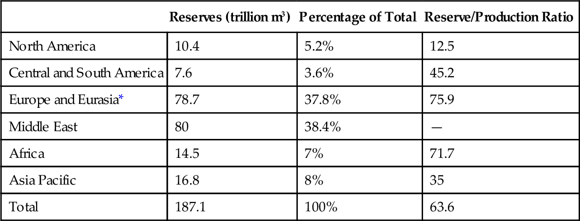
Source: BP Statistical Review of World Energy.
* The figure includes reserves of 44.6 tn m3 in Russia.
When broken down by country, four nations hold the bulk of global reserves. The Russian Federation on its own has 44.6 trillion m3 of proven reserves, 21.4% of the total, and Turkmenistan has 24.3 trillion m3, 11.7% of the total. In the Middle East, Iran holds a further 33.1 trillion m3 (15.9%) and Qatar 25 trillion m3 (12%). Among them these four command 61% of proven global natural gas reserves. Other nations rich in natural gas include the United States with 8.5 trillion m3, Venezuela with 5.5 trillion m3, Saudi Arabia with 8.2 trillion m3, and the United Arab Emirates, Kuwait, Algeria, Nigeria, and Australia.
Natural gas consumption has been rising steadily over the past four decades (Table 4.2). From 651 billion m3 in 1965, consumption had reached 1649 billion m3 in 1985 and 2782 billion m3 in 2005. By the end of 2011 global annual consumption was 3223 billion m3. The largest national consumer, by a wide margin, is the United States, which used 690 billion m3 in 2011, followed by the Russian Federation with 427 billion m3.4 China, by comparison, consumed only 131 billion m3.
Table 4.2
Global Natural Gas Consumption
| Year | Consumption (billion m3) |
| 1965 | 651 |
| 1970 | 987 |
| 1975 | 1186 |
| 1980 | 1437 |
| 1985 | 1647 |
| 1990 | 1960 |
| 1995 | 2135 |
| 2000 | 2412 |
| 2005 | 2782 |
| 2010 | 3169 |
| 2011 | 3223 |
Source: BP Statistical Review of World Energy.
Natural gas is readily transported by pipeline, so this has become the preferred method where pipeline construction is possible. The United States has extensive pipeline networks, as does Europe, while pipelines from central Asian countries and Middle East nations rich in the resource are beginning to extend both east and west.
As a consequence, much natural gas is traded internationally through pipelines. However, where pipeline delivery is not possible, transportation in liquefied form is possible. Major gas producers such as Qatar liquefy gas for delivery by ocean-going tankers to many parts of the world. Important users of liquefied natural gas (LNG) include Japan, Taiwan, and, more recently, the United States and United Kingdom. With its new shale gas resources, the United States is expecting to become an exporter of LNG in the near future.
Global natural gas supplies are sufficient for another 63.6 years, overall, as the figure in the final column of Table 4.1 indicates. However, local national supplies in some regions are under much greater stress. Most striking is North America where existing proven reserves will last only another 12.5 years at current rates of consumption.5
Growth of gas turbine technology
The gas turbine was originally developed during the 1930s and 1940s as an aviation engine and it remained almost exclusively the preserve of the aviation industry until the end of the 1960s. The potential for gas turbines to be used in power generation began to be exploited during the 1970s and early 1980s when they entered service for standby and peak power support on national grids. These early aero-derivative gas turbines were broadly similar in design to the aero engines upon which they were based and shared many components. They were light, they could start up quickly, and they were able to change power output rapidly, making them ideal for a grid support role.
Recognizing the value of gas turbines to the power generation industry, some manufacturers began to design industrial gas turbines intended specifically for this market. These were heavier in construction than their aero-engine counterparts since weight was not an issue for stationary applications such as power generation. As their design evolved, and as their performance was tailored specifically for the power generation market, these industrial gas turbines moved further away from aero engines. At the same time, aero-derivative stationary engines remained in production alongside the new industrial ranges of products.
It was toward the end of the 1980s that the first big combined cycle power plants were built using gas turbines. These used one or more gas turbine generators to produce electricity, with the heat from the turbine exhaust utilized to raise steam in a special heat-recovery boiler. The steam was then used to generate more electrical power in a steam turbine generator. This combination led to a high-performance power plant configuration that, by 1990, was capable of around 50% energy conversion efficiency.
The market for combined cycle power plants grew rapidly during the 1990s, particularly in Europe and the United States where companies operating in the newly liberalized and deregulated electricity markets found the low cost of such plants appealing. Steep rises in the cost of natural gas toward the end of the decade blunted the appeal somewhat. Even so they continued to be popular during the first decade of the 21st century, although gas price volatility during the decade made their economics sometimes questionable. In the second decade of the century with gas availability predicted to rise and prices expected to stabilize, the economics of combined cycle generation look promising again.
To cater for the growing power generation market, the main manufacturers—and there are only a limited number of these because the gas turbine is a very specialized high-technology machine—quickly began to build bigger and more efficient engines. Today, single engines of up to 400 MW in capacity are available. Most of these are aimed at the combined cycle market and have efficiencies on their own between 38% and 42%. However, when used in a modern integrated combined cycle plant the latter should be capable of around 60% efficiency.
Gas turbine principle
A gas turbine is a machine that harnesses the energy contained within a gas—either the kinetic energy of motion of a flowing gas stream or the potential energy of a gas under pressure—to generate rotary motion. In the case of a gas turbine this gas is usually, though not necessarily, air. The earliest human-made device of this type for harnessing the energy in moving air was a windmill described by Hero of Alexandria in the 1st century AD.
This earliest known windmill was a near relative of today’s wind turbine, which though clearly a type of gas turbine, is far removed from the modern gas turbine concept. Closer in concept to the gas turbine was the smokejack, developed in the middle of the 2nd century AD. As described in the 17th century by John Wilkins, Bishop of Chester, the smokejack used hot air rising through a chimney to move windmill vanes within that chimney and drive a shaft that could be used to rotate a spit for roasting meat.
This principle of harnessing moving air within an enclosed chamber to create rotary motion for driving machinery was developed further during the industrial revolution. Following this principle, the 19th century saw a number of predecessors to the gas turbine. These used some form of compressor to generate a human-made flow of pressurized air that was fed into an enclosed turbine. In these machines the compressor was usually separate from the turbine.
The direct ancestor of the modern gas turbine was first outlined in a patent granted to German engineer F. Stolze in 1872. In Stolze’s design, as in that of all modern gas turbines, an axial compressor was used to generate a flow of pressurized air. This air was then mixed with fuel and ignited, creating a very energetic flow of hot, high-pressure gas that was fed into a turbine. Crucially, the compressor and the turbine were mounted on the same shaft (Figure 4.1).
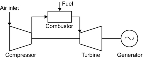
Whereas a gas turbine supplied with pressurized gas from a separate compressor must inevitably rotate provided it has been designed correctly, the arrangement patented by Stolze need not necessarily do so. This is because the energy to operate the compressor that provides the pressurized air to drive the turbine is produced by the turbine itself. Thus, unless the turbine can generate more power than is required to turn the compressor—the energy for this being provided by the combustion of fuel in the compressed air that same compressor has produced—the machine will not function. This, in turn, demands efficient compressors and turbines. Both need to operate at a minimum efficiency of around 80%. Only if this condition is met will the turbine operate in a continuous fashion.
The turbine system described by Stolze, although envisaging virtually all the features of a modern gas turbine, was not capable of sustained operation because the machinery sophisticated enough to achieve it had not yet been developed. The first machine that was able to operate in a sustained fashion was built in Paris in 1903. This, though, did not have a rotary compressor on the same axis as the turbine. That honor fell to a machine built by Aegidus Elling in Norway and operated later in 1903. In Elling’s machine the inlet gas temperature was 400 °C, high for its time though much lower than gas turbine inlet temperatures today.
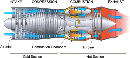
Development of the gas turbine based on this principle continued through the early years of the 20th century with the aim of generating either a flow of compressed air, rotary motion, or both for industrial use. Then, during the 1930s, the potential of the gas turbine to provide the motive force for flight was recognized and aircraft with jet engines based on the gas turbine were developed in Germany, Great Britain, and the United States. These led, in turn, to the modern aircraft engines that power the world’s airline fleets.
During the late 1970s and early 1980s, as already noted, gas turbines began to find a limited application in power generation, and during the 1990s this use expanded with development of combined cycle power plants.
Modern gas turbine design for power generation
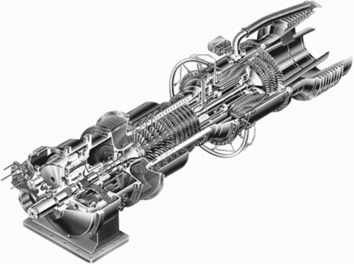
A modern gas turbine maintains the three principle components of the Stolze design: a compressor, a combustion chamber, and a turbine stage (Figure 4.2). As in that design, these are closely coupled with the two rotary components on the same axis. The main energy-producing component is the turbine stage that, as outlined earlier, drives its own compressor as well as provides energy to turn a generator and produce electricity.
The turbine stage of a gas turbine is a thermodynamic heat engine. As with all heat engines, the efficiency of its operation depends on the amount of energy it can extract from the operating fluid (in this case air). For an ideal heat engine this in turn depends on the temperature and pressure difference between the gas entering the engine inlet and the gas at the turbine exhaust.
It is in the operation of the turbine stage that aero engines and power generation turbines diverge. An aero engine only needs the turbine to produce sufficient rotary power to drive its compressor. All the rest of the energy within the gas should be delivered through the turbine exhaust as a high-pressure flow of gas providing thrust. For a power generation turbine, as much energy as possible should be captured in the turbine rotary motion and as little energy as possible should exit through the turbine exhaust, which should release gases at the lowest temperature and pressure possible.
The input energy for the turbine depends on both temperature and pressure of the air at the turbine inlet. The pressure is a design feature that will vary from manufacturer to manufacturer and is defined by the compression ratio chosen for the design. All modern gas turbines utilize axial compressors that draw in and compress air. These comprise several stages of blades (much like a series of windmills but operating in reverse) to compress air to between 15 and 30 times atmospheric pressure, depending on the design (i.e., the compression ratio is between 15:1 and 30:1). A modern unit might have 10–12 sets of compressor blades (also called stages). Efficiency is typically 87%.
High-pressure air from the compressor then enters a combustion chamber where it is mixed with fuel and ignited, increasing the temperature of the air to as high as 1600 °C. At temperatures this elevated, nitrogen from air is easily oxidized to produce nitrogen oxides, which will then appear in the gas turbine exhaust. Since nitrogen oxide emissions must be controlled, gas turbine combustion chambers are designed to maintain reducing conditions as far as possible, with staged combustion to limit the production of nitrogen oxide. In some cases water is injected into the combustion chamber to reduce nitrogen oxide levels but most large turbines use dry combustion chambers.
Combustion chambers come in a variety of designs and dispositions. In some gas turbines they are kept separate from the turbine body. Other designs position them within the body, between compressor and turbine stages, while in others there are multiple combustion chambers arranged annularly around the body of the turbine. At least one manufacturer uses sequential combustion similar in concept to reheat in a steam turbine. In this case the turbine stage of the unit is split into two parts and the hot gases exiting the first part pass into an additional combustion chamber where further fuel is ignited to increase temperature and pressure again before entering the second part.
The turbine stage of a modern gas turbine will normally comprise three to five stages of blades (windmills operating as windmills in this case) operating with an efficiency of around 89%. Some designs have both compressor and turbine blades mounted rigidly onto the same shaft (Figure 4.3). In others there are two concentric shafts—one carrying the compressor blades and the first one or two turbine stages. These turbine stages power the compressor while the latter stages, on a second shaft, are attached to a generator and produce power. Some aero-derivative gas turbines take this complexity a stage further with the compressor also divided into two parts too—a low-pressure compressor and a high-pressure compressor. The low-pressure compressor is driven by the low-pressure turbine stage of the unit and, via a concentric shaft, the high-pressure turbine drives the high-pressure compressor.
The exhaust gases from a simple gas turbine generator are released to the atmosphere. For the most efficient aero-derivative gas turbine, the outlet gas temperature will be around 400 °C to 500 °C. This represents a significant energy loss. Even so, such units can be relatively efficient. In fact, these aero-derivative gas turbines are usually the most efficient of all gas turbines with the best recording an energy conversion efficiency of 46%. Power output from this type of turbine is usually under 100 MW. Small industrial turbines tend to have slightly lower efficiencies, up to 42%.
For an open-cycle gas turbine (i.e., one not operating in a combined cycle plant), lower exhaust gas temperature equates to higher efficiency, which in turn equates to better economy. In a combined cycle plant, on the other hand, a higher exhaust gas temperature is usually preferable because this allows the second part of the plant, based on a steam turbine, to operate more efficiently. Thus, most of the largest industrial gas turbines that are principally designed for combined cycle operation will actually have a lower efficiency in open-cycle mode than some smaller turbines to obtain the best efficiency in combined cycle mode. The largest industrial gas turbines have efficiencies between 38% and 42%.
Gas turbine development
Efficiency is perhaps the most important operating parameter for all gas turbine operations. In aero engines, higher efficiency equates to lower fuel costs. Similarly in the power industry, higher efficiency leads to a lower unit cost for electricity generation. Efficiency is important from an environmental perspective too, because the more efficient a gas turbine–based power plant is at generating electricity, the less carbon dioxide and other atmospheric pollutants the power plant will create for each unit of electricity it produces.
As a consequence, the main focus of gas turbine development over the past 20 years had been primarily aimed at increasing efficiency. Overall, efficiency will depend on the efficiency of both the compressor and the turbine, but with both of these now highly efficient, the main means available to gas turbine designers to improve efficiency are by increasing temperature and pressure of the gas entering the turbine (i.e., heat engine) stage of the unit.
The engine compression ratio (the amount by which the compressor increases the inlet air pressure) is one variable available to designers to modify as they seek higher efficiency, but the chosen ratio is generally an optimum for a particular design rather than the highest possible. As already noted, compressor design has reached a high level of sophistication and modern compressors can deliver whatever pressure is required within the stationary gas turbine range of 15:1 to 30:1 at high efficiency.6
The design of the turbine stage has also reached a very high level of technical sophistication, with the shapes of the rotating blades and the stationary vanes (sometimes called nozzles) optimized using computer modeling. Thus, the only major variable still open to improve overall efficiency is turbine inlet gas temperature.
Gas turbine combustors are capable of delivering gas at higher temperatures that are currently in use, but the maximum temperature that can be exploited is limited by the performance of the materials employed in the early stages of the gas turbine. Inlet temperatures at the first stages of gas turbines have risen steadily, from around 900 °C in 1967 to 1425 °C in 2000 and 1600 °C in 2010. Efforts to raise temperatures further are underway and a Japanese program is aiming to achieve 1700 °C in the near future.
Such high temperatures place extreme demands on the materials used in turbine construction, which have to withstand these extreme conditions. The turbine blades, the vanes that control air flow from one set of blades to the next, and other hot-gas-path components are commonly made from nickel-based alloys cast in single crystal form to increase their resistance to deformation or fracture. However, these alloys start to soften at anywhere between 1200 °C and 1400 °C. To render them capable of withstanding higher temperatures they are coated with a ceramic thermal barrier coating (TBC) comprising a material (often based on zirconia) with a low thermal conductivity. On its own, this TBC will not prevent the components from reaching the temperature of the inlet gases so the blades and other components must also be cooled internally by pumping air or steam through channels within them.
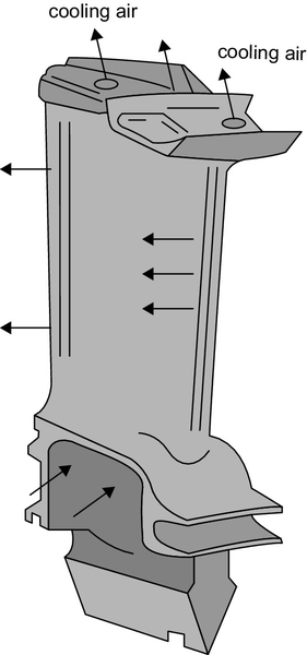
Air cooling requires hot air that is “stolen” from a later stage of the turbine. This has the effect of lowering overall efficiency but is simpler to design. In a combined cycle plant steam can be taken from the steam generator and used for cooling. This involves a smaller efficiency penalty but is more complex and can have an effect on overall plant flexibility. See Figure 4.4 for a diagram of gas turbine blade cooling.
While greater efficiency has been a primary goal for modern gas turbine manufacturers, another that has come to prominence since the beginning of the 21st century is flexibility. Flexibility is most important for large, high-efficiency combined cycle plants. Smaller, open cycle gas turbines can generally be operated flexibly with little penalty. The goal of flexible operation is to be able to maintain good efficiency at part load as well as full load, and to be able to change load quickly. To achieve this, many involve sacrificing the ultimate level of efficiency. Flexible operation for combined cycle power plants will be examined in more detail later in the chapter.
Advanced gas turbine cycles
The basic gas turbine configuration as just outlined can be modified in a number of ways to attempt to enhance the performance. Reheating, alluded to briefly already, involves adding a second combustion stage and splitting the turbine section into two parts. Intercooling is an analogous modification to the compressor in which this is divided into two stages, with cooling of the air in between them. Water vapor or steam injection into the inlet air before, within, or after the compressor can increase overall efficiency by creating a larger mass flow for less energy input. Finally, it is possible to capture some of the heat from the exhaust of a simple cycle gas turbine and use it to heat the compressed air from the compressor stage before it enters the combustion chamber, again leading to an improvement in efficiency. Some of these modifications can be utilized in gas turbines within combined cycle configurations, and others are only useful when the gas turbine is operating in an open cycle.
Reheating
In large steam turbine–based power plants it is traditional to split the turbine into separate sections: one handling high-pressure steam, one handling intermediate-pressure steam, and a third handling low-pressure steam. By splitting the turbine this way, efficiency gains can be made through matching the individual turbine sections to operate under a narrower range of steam pressures. Further, once the turbine has been split into separate sections, additional efficiency gains can be made by reheating the steam when it exits the high-pressure turbine (where it will have cooled) and before it enters the intermediate-pressure turbine. This is a common feature of the steam turbines used in coal-fired power plants.
The power turbine stage of a gas turbine can also be divided up in a similar way, though normally only two separate sections, called spools,7 are used as shown in Figure 4.5. One of these is called the high-pressure spool and the second a low-pressure spool. Once the turbine has been split into spools it is possible to introduce a second combustion stage to reheat the air between the high-pressure and low-pressure spool of the power turbine. Reheating increases turbine efficiency in the same way as for a steam turbine by optimizing power turbine and gas flow conditions. Further, it can allow the turbine to achieve higher efficiency with a lower turbine inlet temperature, making less demand on material performance.
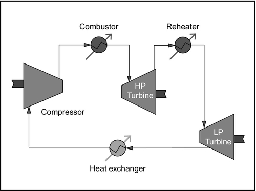
Reheating is used by at least one major manufacturer8 to achieve high efficiency in large gas turbines. These units also operate at a relatively high compression ratio of 30:1, similar to many aero-derivative gas turbines.
Intercooling
It is possible to go a stage further with a gas turbine by splitting the compressor into two sections: a low-pressure compressor section and a high-pressure compression section. As with the reheating of the air between the two spools of the turbine, it is possible to improve efficiency by cooling the air between the two spools of the compressor. (Compressing air generates heat, which raises the temperature of the air and hot air occupies a larger volume. Cooling it reduces the volume so the compressor actually has less work to do.) This is called intercooling.
Intercooling a high-performance aero-derivative gas turbine can boost its efficiency by around 5%, double its power output, and substantially reduce the cost per kilowatt of generating capacity.9
Recuperation
A third strategy for improving the performance of a gas turbine is to use heat from the turbine exhaust to partially heat the compressed air from the compressor before it enters the combustion chamber. This process, referred to as recuperation, results in less fuel being needed to raise the air to the required turbine inlet temperature (Figure 4.6). In effect, the recuperated gas turbine cycle is allowing more energy to be captured from the air, increasing overall thermodynamic efficiency.
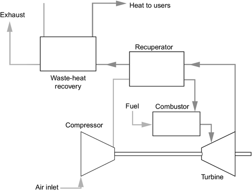
Recuperation uses heat in the gas turbine exhaust that would be captured in a combined cycle plant so this technique will not normally be applied in that configuration. However, it has been used successfully in a number of small gas turbines to provide higher efficiency. It is also a feature of many micro-turbines.
Mass Injection
A final strategy for increasing efficiency of a gas turbine is to inject water or water vapor into the air supplied to the turbine. Injection may take place at the compressor inlet, at stages through the compressor, or at the combustion chamber. In all cases the aim is to increase mass flow through the turbine.
The steam-injected gas turbine (STIG) cycle involves using a heat-recovery steam generator to produce steam from the exhaust gas of the gas turbine in much the same way as in a combined cycle station. This steam is then injected into the combustion chamber of the turbine. This increases the mass flow into the turbine stages with a consequent increase in overall efficiency. An added advantage is that injection of steam into the combustion chamber can reduce Nitrogen oxide generation. A STIG cycle can increase overall gas turbine efficiency between 2% and 4%.
The humid-air turbine (HAT) cycle is a more complex cycle in which inlet air is intercooled part way through the compressor and at the exit of the compressor and then passed through a humidifier where it becomes almost saturated with water vapor before entering the combustion chamber. Recuperation is then employed to heat the humidified air and gain the highest possible efficiency in use of energy. For small gas turbines, this cycle is potentially more efficient than the equivalent combined cycle configuration.
Other HAT cycles are also possible. The cascaded HAT (CHAT) cycle introduces a reheating stage between the high-pressure spool and the low-pressure spool of the power turbine. Another variant called TOP Humid Air Cycle (TOPHAT) injects water into various stages of the compressor while the advanced HAT (AHAT) cycle injects water at the compressor inlet.
Various claims have been made for the HAT cycle and its variants with efficiencies as high as 55% in a large CHAT system. These suggest that in principle a HAT cycle turbine can approach the efficiency of a combined cycle power plant but without the complexity of a steam turbine and at lower inlet temperatures. However, the cycle cannot complete with the efficiency levels now being achieved in large combined cycle plants. Another disadvantage of HAT and CHAT cycle power units is that they release a considerable amount of water vapor into the environment. In situations where water is scarce it may be necessary to recover the water from the exhaust gas, adding to cost and complexity.
Along with the cycles described here there are a number of other variants of both the STIG and HAT cycles. Most have not been widely adopted commercially.
Combined cycle power plants
The advanced cycles previously discussed offer the potential to increase gas turbine energy conversion efficiency. Where they have been applied, it has generally been for small generating systems. The most important adaptation of the gas turbine cycle, however, is the combined cycle power plant. This is a configuration that has been adopted and adapted by all gas turbine manufacturers, and it is capable of the highest energy conversion efficiency yet recorded for a large commercial fossil fuel–fired power station.
The efficiency of a gas turbine for electricity generation is always limited by the fact that the exhaust gases leave the turbine at a high temperature and therefore still contain a large amount of energy that has not been recovered. Some of the techniques described earlier attempt to use some of this heat energy. However, the most straightforward way of doing so is to add what is known as a bottoming cycle. This is an additional heat engine cycle operating on the low-temperature exhaust.10 For a gas turbine, the best match for a bottoming cycle is a steam turbine.
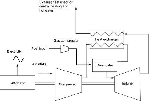
To integrate the two, the exhaust from the gas turbine is fed into a specially designed heat-recovery steam generator that produces steam from the hot air. This steam is then used to drive a steam turbine generator that produces an additional amount of electricity (Figure 4.7). This basic design is capable of being interpreted in various ways. In some plants there will be a single steam turbine that is fed by steam generated from the exhausts of two or three gas turbines. In others, each gas turbine has its own steam turbine. In some cases these may be integrated on a single shaft with the gas turbine at one end, the steam turbine at the other end, and a generator in the middle driven by both. In this case it will usually be possible to decouple one or both of the turbines from the generator.
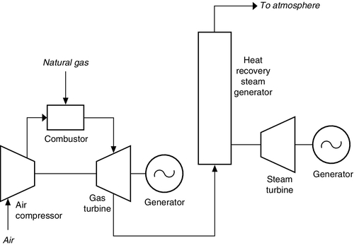
The development of gas turbine combined cycle plants since the late 1980s has led to a significant increase in energy conversion efficiency. In 1990, the best efficiency was around 50%. In 2011, a gas turbine combined cycle plant in Germany achieved 60.75% efficiency. Part of this improvement has been due to tight integration of all the combined cycle plant components to reduce heat loss. However, much of it has been due to an increase in the turbine inlet temperature, which has permitted greater thermodynamic efficiency. Inlet gas temperatures have already reached 1600 °C in the hottest machines developed in Japan where a government program is aiming to make 1700 °C feasible, with a potential combined cycle efficiency of perhaps 65%.
The high efficiency of gas turbine power plants helps keep the cost of each unit of electricity down (though this depends critically on the price of natural gas). They are also attractive because they generate less carbon dioxide for each unit of electricity than other types of fossil fuel generation. In addition, the plants are cheap to build and can be erected relatively quickly because many of the components can be supplied to the power plant site already assembled.
Combined cycle plants can be built in a range of sizes for a few megawatts to several hundreds of megawatts, although sizes are limited by the unit sizes that the different manufacturers offer. While all have a part to play, it is the larger ones that have assumed the most importance in the market.
Originally these large combined cycle plants were conceived as base-load power generation units that would operate at full load for most of the time. The volatility of gas prices during the late 1990s and the first decade of the 21st century has often made this economically unviable and plants have frequently operated at capacity factors much lower than 100%. In the United States the typical capacity factor has been 40% or less in most recent years.
The duty cycle of the gas turbine plant has additionally been complicated by the increasing volumes of electricity entering grids in many parts of the world from renewable power stations exploiting wind or solar energy. The fluctuating output from these sources means that these grids require a secondary source of electricity to maintain the grid in balance. This is a role that combined cycle power plants are being adapted to fill.
To achieve flexibility, manufacturers are modifying the way their combined cycle plants operate. Flexible operation includes being able to generate at much less than 100% load while still maintaining good efficiency. It means being able to start up quickly and being able to change output quickly too, all without compromising either efficiency or emissions performance. Strategies to achieve this include keeping parts of the system continually warm by either heating them or by keeping the plant on-line at very low load (sometimes called parking) when demand is low—sometimes overnight—so that it can return to full output quickly. Various modifications to the way plants operate have allowed plants to change their outputs much more quickly than in the past.
Most large combined cycle plants have one to three gas turbines. However, some manufacturers are also exploring the option of using many more small gas turbines, each with its own steam generator and steam turbine, to provide greater flexibility. Each of the multiple units can then be brought into service as needed. Increasing or decreasing output is then managed by starting up or shutting down another unit so that operating units are at their optimum load for most of the time. This allows overall high efficiency to be maintained over a wide range of loads but at the expense of ultimate efficiency, because smaller gas turbines are generally less efficient than the largest machines.
Micro-turbines
Micro-turbines are tiny gas turbines that can generate both electricity and heat. They vary in electrical output from around 25 kW to 250 kW. Units of between 250 kW and 500 kW are sometimes called mini-turbines. The two types are designed to be used in large domestic or small commercial environments where they can provide both forms of energy. As such, they are usually designated as distributed generators since they supply their power at the distribution level of the grid.
Depending on the source, micro-turbines are described as having evolved from turbochargers in automotive engines or auxiliary power units for aircraft. Whatever their origin, they are identical in their main components to conventional gas turbines with a compressor, a combustion chamber, and a power turbine (Figure 4.8). The main difference, apart from their size, is that a micro-turbine will only have one set of compressor blades and one set of turbine blades.
In most micro-turbines the generator is packaged with the turbine to provide a single unit that can be installed rapidly and with little preparation. As a consequence of their small size, micro-turbines and their generators operate at very high rotational speeds, typically between 40,000 rev/min and 120,000 rev/min. Generators rotating at these speeds cannot be connected directly to the grid. Instead they are connected through a solid-state interface that converts the high-frequency AC power produced by the generator to 50 Hz or 60 Hz as required to synchronize with the grid.
There are two general types of micro-turbine package available: simple and recuperated. The simple micro-turbines tend to be the more robust but their energy conversion efficiency is low at around 15%. However, this leaves a significant amount of waste heat in the turbine exhaust for supplying hot water in a cogeneration application. Recuperated micro-turbines use waste heat to heat compressed air between the compressor stage and the combustion chamber in exactly the way as industrial and aero-derivative gas turbines. Recuperation on a micro-turbine can increase overall conversion efficiency between 20% and 30%. With both types, waste heat capture for hot water can raise overall cogeneration efficiency to 85%.
Most micro-turbines are designed to burn natural gas. A packaged system will comprise the micro-turbine generator, a gas compressor to provide natural gas at the pressure required by the turbine combustion chamber, a solid-state grid interface, and, in many cases, a waste heat-recovery system. They have very low emissions and can be installed in domestic and commercial environments. Micro-turbines are more expensive than similarly sized reciprocating engines, but research is continuing with the aim of achieving much higher energy-to-electrical conversion efficiencies.
Emission control for gas turbine power plants
The combustion of natural gas, the main fuel for gas turbines, has a relatively low environmental impact when compared to its main fossil fuel competitor, coal. After it has been cleaned it contains relatively little if any hydrogen sulfide and no heavy metals. Depending on the precise composition of the natural gas and on the gas turbine combustion system in which it is burned, its combustion will generate some carbon monoxide and also some particulate material, both resulting from incomplete combustion of components of the fuel. Aside from these, the main atmospheric pollutant of concern with gas turbine power generation is nitrogen oxide generated by oxidation of nitrogen in the combustor. Levels of carbon monoxide, particulates, and nitrogen oxide can peak during startup and under part-load operation.
Gas turbines also generate carbon dioxide from the combustion of the hydrocarbon fuel they burn. The quantity generated for each unit of electricity is much less than would be released from a coal-fired power station, but even so, large combined cycle power plants are major carbon dioxide emitters.
Nitrogen Oxide
Nitrogen oxide can be produced in gas turbines from two different sources. Small amounts of nitrogen can be found bound in the fuel itself as part of the complex mixture of hydrocarbon-based materials that can make up natural gas. This nitrogen, when it exists, will be converted into nitrogen oxide during combustion. However, the main source of nitrogen oxide is from nitrogen gas, either from the air in which the gas is burned or actually contained in small amounts with the fuel.
Most nitrogen oxide production is the result of the oxidation of nitrogen gas by oxygen in the air at the high temperatures that are reached in the combustor of the gas turbine. With power turbine inlet temperatures as high as 1600 °C or greater in large high-efficiency gas turbine combined cycle systems, this presents a significant problem. The solution has been to develop low nitrogen oxide burners that control the combustion in such a way as to limit nitrogen oxide production.
One successful technique that has been applied in a range of gas turbine combustors is water or steam injection. This serves to lower the combustion temperature and thereby reduce nitrogen oxide production. However, as temperatures have risen higher, these have been replaced by dry low nitrogen oxide burners that achieve the same end without water injection.
The simplest way to burn natural gas in air is to pump the gas through a fine nozzle where it is ignited as it enters the atmosphere. With unlimited amounts or air, and therefore of oxygen available, this diffusion or spray combustion results in a stable flame within which optimum combustion conditions will ultimately be reached, leading to complete combustion and limited formation of carbon monoxide and particulate material. However, this unrestrained combustion can also lead to high levels of nitrogen oxide.
The main alternative and the technique that is now used in most dry low nitrogen oxide burners is called premixed combustion. This involves premixing the natural gas with a carefully controlled quantity of air before it enters the combustion chamber, such that there is just sufficient oxygen to react with the combustible gas but none left to react with nitrogen. Controlling combustion under these conditions is much more difficult. If there is too little air then combustion is incomplete and will result in high concentrations of carbon monoxide and unburned material, leading to harmful emissions and lower efficiency because all the energy within the fuel is not utilized. On the other hand, if the amount of air becomes too high, then nitrogen oxide levels quickly rise.
Therefore, premixed combustion must be carefully controlled. When it is, modern low nitrogen oxide burners are capable of reducing the emissions of nitrogen oxide to between 15 ppm to 25 ppm for large industrial gas turbines and as low as 9 ppm for some smaller gas turbines. Nitrogen oxide emission standards are typically 25 ppm in many parts of the world and manufacturers aim to meet these standards without further control being necessary. However, standards are tightening and some areas are introducing emission limits of 15 ppm or 10 ppm for gas turbines. These are much harder for large combined cycle plants to meet without further nitrogen oxide reduction systems.
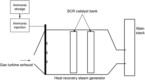
Where low nitrogen oxide burner technology cannot meet the required emission standard, manufacturers have to turn to an alternative post-combustion technology. The most common of these is selective catalytic reduction (SCR). SCR involves injecting a reducing gas, usually ammonia or, sometimes, urea, into the exhaust gases after they exit the power turbine and then passing the mixture over a metal catalyst that catalyzes the reaction between the ammonia, or urea, and nitrogen oxide to produce nitrogen and water vapor. In a combined cycle power plant the SCR unit is often placed within the heat-recovery steam generator as shown in Figure 4.9.
Catalysts for SCR are normally either a metal or metal oxide on a ceramic carrier. Various metals have been used, including vanadium, molybdenum, and tungsten, as well as platinum, though the latter is mostly found in the system used in car exhausts. The type of catalyst will depend on the temperature of the exhaust gases. Metal oxides are more temperature resistant than metals.
In principle, an SCR-based nitrogen oxide reduction system can remove 95–99% of the nitrogen oxide from the exhaust gases. However, the system becomes more difficult to control when reduction levels exceed 80% because the reaction does not proceed as smoothly, putting greater demands on the catalyst and often leading to higher levels of ammonia or urea passing through the system and being released into the atmosphere. This is referred to as ammonia slip.
Therefore, the optimum solution is a balance between low nitrogen oxide burners and SCR such that both operate within the best range of efficiency. With both, it is possible to reduce nitrogen oxide emission levels below 10 ppm and often much lower than this. Targets of 4–5 ppm appear to be achievable with modern systems.
Carbon Monoxide
Carbon monoxide can be generated in gas turbines as a result of incomplete combustion of the natural gas fuel. Emissions of carbon monoxide are controlled in the same way as those of nitrogen oxide with similar limits of 10–25 ppm in operation. Low nitrogen oxide burner technology can lead to levels of carbon monoxide higher than this, under which circumstances some system of emission control is needed. This is usually in the form of an oxidation catalyst that catalyzes the conversion of carbon monoxide into carbon dioxide. This may be a separate catalytic unit, but in combined cycle plants it is often incorporated into the heat-recovery steam generator too.
Carbon Dioxide
The combustion of natural gas generates significant quantities of carbon dioxide. Although the rate of production is much lower than in a coal-fired power plant, the gross level of production can be large. In the United States in 2009, for example, gas turbine–based power plants accounted for 23% of total power generation and 13% of carbon dioxide emissions.
For each kilowatt of energy contained in natural gas, its combustion will produce 0.23 kg of carbon dioxide. For coal the equivalent figure is 0.37 kg/kWh. The actual emissions per unit of electricity produced will depend on the efficiency of electricity production, but a combined cycle plant operating at 55–60% efficiency will emit relatively less than a coal plant at 38–45% efficiency.
Combined cycle plants are considerably less carbon intensive than coal-fired plants, and this has been one of the driving forces behind a switch to more natural gas–fired power generation in the developed world. Even so, when carbon capture from power plants becomes necessary, it is unlikely that combined cycle units will be exempt.
The main methods of reducing or eliminating carbon emissions from gas turbine–based power plants are exactly the same as those for coal-fired power plants that were discussed in Chapter 3: post-combustion capture, pre-combustion capture, and oxy-fuel combustion. The concentration of carbon dioxide in the flue gases from a typical combined cycle power plant will be 3–4%. This is much lower than in the flue gases of a coal-fired power plant and makes post-combustion capture relatively more difficult. On the other hand, the low concentration means that less needs to be removed.
Post-combustion capture using an ammonia or monoethanolamine absorbent in a spray tower is likely to be the most effective form of post-combustion capture for combined cycle plants. It is also an efficient means of retrofitting capture technology. The problem of low carbon dioxide concentration in the exhaust gases can be mitigated by recycling exhaust gases back to the gas turbine inlet. This has the effect of increasing carbon dioxide concentration but also of reducing the available oxygen entering the combustion chamber. Exhaust gas recycling of up to 35% appears to be effective without adversely affecting the combustion conditions. With exhaust gas recycling, post-combustion capture should be able to remove 90% of the carbon dioxide generated. Overall energy conversion efficiency is reduced by perhaps 6–8%.
Pre-combustion capture is essentially analogous to the coal gasification technology discussed in Chapter 3, producing hydrogen fuel gas that is then burned in a gas turbine combined cycle power plant. In the case of natural gas the process is known as reforming and is widely carried out industrially to make hydrogen. As with post-combustion capture, the capture efficiency is likely to be around 90%, but the overall generation efficiency is likely to fall more, perhaps by 10%.
Oxy-fuel combustion involves burning the natural gas in pure oxygen instead of air. This requires an oxygen separation plant but leaves an exhaust gas that is rich in carbon dioxide and containing little nitrogen, making it much easier to isolate. Capture efficiency may be as high as 99%. As was the case in a coal-based oxy-fuel plant, the combustion temperature when natural gas is burned in oxygen is far higher than in air—too high for the materials currently available to withstand. To counter this, carbon dioxide–rich exhaust gases are fed back to the gas turbine inlet to dilute the oxygen, reducing the combustion temperature to a level similar to that for air combustion. Overall energy conversion efficiency is likely to fall by up to 8–9% compared to a gas turbine plant without capture.
Cost of gas turbine–based power generation
The capital cost of a gas turbine–based power plant depends primarily on the cost of the gas turbine. This is a high-technology component that is manufactured by a small number of companies, mostly based in developed countries. However, even the largest gas turbines are off-the-shelf components that can be supplied virtually ready to operate. Competition between different manufacturers is stiff, and in many cases the key negotiating tool is price. As a consequence, gas turbines tend to be extremely competitively priced and they represent one of the least capital cost forms of power generation, particularly in the shape of a large combined cycle power plant.
Against that, the fact that gas turbines are high-technology components means that their cost will always be affected by shifts in commodity prices for the materials, especially the metals, from which they are built. This will be magnified in a combined cycle plant as a result of the cost of the heat-recovery steam generator, made primarily from steel and the steam turbine, again built mostly from steel. However, the fact that major components of a combined cycle plant can be delivered ready-assembled reduces labor costs.
Table 4.3 contains costs for gas turbine–based power plants in the U.S. market, based on analysis by the U.S. Energy Information Administration (EIA). While costs in other parts of the world will differ, the fact that these units are traded, internationally, means that prices are likely to be similar, whatever market is being considered. Based on this U.S. EIA analysis, which considers costs for plants in year 2010 U.S. dollars and where the order was placed in 2011, the cost of a conventional natural gas–fired combined cycle plant is $931/kW. An advanced combined cycle plant with the most efficient gas turbines available would actually be slightly cheaper at $921/kW. Typical plant sizes for these two types of plant are shown in Table 4.3.
Table 4.3
Capital Cost of Gas Turbine–based Power Generation
| Type of Gas Turbine Plant | Plant Capacity (MW) | Capital Cost ($/kW) |
| Conventional gas turbine combined cycle plant | 540 | 931 |
| Advanced gas turbine combined cycle plant | 400 | 929 |
| Advanced gas turbine combined cycle plant with carbon capture and storage | 340 | 1834 |
| Conventional open cycle gas turbine plant | 85 | 927 |
| Advanced open cycle gas turbine plant | 210 | 634 |
Source: Assumptions to the Annual Energy Outlook 2012, U.S. Energy Information Administration.
Note: The figures used in the table are base overnight costs in 2010.
Carbon capture and storage is expected to increase the cost of fossil fuel power generation considerably. In Table 4.3, the cost for an advanced gas turbine combined cycle plant with carbon capture and storage is estimated to be $1834/kW, or slightly under twice the cost of either type of plant without carbon capture and storage. A conventional open cycle gas turbine plant, likely to be used primarily for peak power and grid support services, costs $927/kW or virtually the same as the combined cycle plants without carbon capture and storage. This plant would, however, operate with significantly lower efficiency than the combined cycle plant, as explained before. Meanwhile, an advanced gas turbine in an open cycle configuration is expected to cost $634/kW. The two types of open cycle plant are expected to have a lead time from order to entering service of two years. For the combined cycle plants the lead time would be three years.
Table 4.4 shows some future costs for combined cycle power plants burning natural gas based on a report from the U.S. Electric Power Research Institute (EPRI). Again, the figures apply to the U.S. market but should be broadly indicative of prices elsewhere. EPRI calculated that a combined cycle power plant without carbon capture entering service in 2015 would have a capital cost of $1060–1150/kW. EPRI expects the cost to be broadly unchanged in 2025. Meanwhile a similar plant, but with carbon capture, is predicted to cost between $1600/kW and $1900/kW.
Table 4.4
Capital Costs in 2015 and 2025 for U.S. Gas-fired Combined Cycle Plants
| Plant | 2015 ($/kW) without Carbon Dioxide Capture | 2025 ($/kW) Carbon Capture and Storage |
| Natural gas combined cycle plant | 1060–1150 | 1060–1150 |
| Natural gas combined cycle plant with carbon capture | n/a | 1600–1900 |
Source: Program on Technology Innovation: Integrated Generation Technology Options, Technical Update, June 2011, Electric Power Research Institute, 2011. (EPRI reference 1022782.)
The low capital cost of gas turbine–based power generation is one of the reasons why they have been favored by private sector companies operating in the liberalized electricity markets established around the world. The cost remains low compared to most other technologies even when carbon capture and storage is included. However, that does not necessarily translate into a low cost for electricity generated by these plants.
The main problem with natural gas–based power generation is the cost of gas. When this is low, combined cycle power plants are extremely competitive sources of electric power. However, when prices rise, and in global energy markets the price can rise extremely rapidly, they can become far from economical. The uncertainty attached to the volatility in gas prices can also have a damaging effect on the economic growth in countries that rely heavily on gas-fired generation.
The IEA predictions of a golden age of gas, if they come to pass, may lead to a loosening of gas supplies, a lowering of average prices, and a reduction in volatility. If so, then gas-fired generation is likely to thrive well into the 21st century.