
Hydropower
Abstract
Hydropower is one of the oldest sources of mechanical power and the largest source of renewable electricity generation in use. Global capacity is around 1000 GW. Hydropower is site specific and so each project will be unique. Hydropower plants are classified according to their size into micro-, mini-, small, and large hydropower. In terms of generating the capacity the large plants are the most important. These can be either dam and reservoir plants or run-of-river schemes. The latter are the easiest to construct and least disruptive, but the former stores energy and is therefore much more flexible in the way it can be used. Energy is taken from hydropower plants through turbines and a number of designs such as Pelton, Francis, and Propeller turbines exist to exploit different head heights of water. Most hydropower developments have environmental effects that must be taken into account before construction.
Hydropower is probably the oldest renewable energy resource in the world and one of the first sources of mechanical power. The earliest known reference is found in a Greek poem from 85 BCE and there are references in Roman texts too. Simple wheels used to drive mills and grind grain were known in China during the 1st century, and by the beginning of the second millennium the technology was widely known throughout Asia and Europe.
Early mills used wooden paddles but iron was introduced in the 18th century during the Industrial Revolution in England. Innovation soon led to the development during the 19th century of many of the turbines now in use in modern hydropower stations.
Hydropower capacity grew strongly during the 20th century and until late in that century it was the only significant renewable source of electrical power. According to the Renewable Energy Policy Network for the 21st Century (REN21) Global Status Report for 20131 total global hydropower capacity at the end of 2012 was 990 GW excluding pumped storage hydropower capacity. This is an increase of 115 GW compared to the estimate of global capacity from the World Energy Council for the end of 2008 of 875 GW, as shown in Table 8.1. According to the International Hydropower Association, global capacity includes at least 11,000 power stations and 27,000 generating units. REN21 put total global electricity generation from hydropower in 2012 at 3700 TWh, around 15.5% of total global electricity generation, which stood at 22,500 TWh in 2012 according to the BP Statistical Review of World Energy.
Table 8.1
Regional Installed Hydropower Capacity
| Installed Hydropower Capacity (GW) | Percentage of Global Total | |
| Asia | 307 | 35% |
| Europe | 221 | 25% |
| North America | 168 | 19% |
| South America | 132 | 15% |
| Africa | 22 | 3% |
| Oceania | 14 | 2% |
| Middle East | 11 | 1% |
| Total | 875 | 100% |
Source: World Energy Council.
Hydropower is widely distributed and few regions are without significant hydropower potential. The countries of the developed world have exploited many of their best sites already and hydropower generation forms part of the bedrock upon which developed nations’ prosperity is based. Development elsewhere has been slower but there have been major advances in Asia, particularly in China, in recent years, and many of the countries of South America rely heavily on hydropower for electricity generation. Even so, most of these regions have much remaining capacity, while in Africa hydropower is significantly underdeveloped. Table 8.1 shows the breakdown of global capacity at the end of 2008 based on figures from the World Energy Council’s 2010 Survey of Energy Resources.
In spite of its potential and obvious advantages, the development of hydropower can often be difficult, particularly where large projects are concerned. Major hydropower projects are often extremely disruptive and, if not developed sensitively, they can lead to a range of environmental problems. Large hydropower plants, particularly those involving dams and reservoirs, will inevitably change the environment in which they are constructed, leading to displacement of people and wildlife and the destruction of ecologies. With care these changes can be managed, but careless and sometimes reckless development during the second half of the 20th century led to hydropower acquiring a bad reputation during the 1980s and 1990s.
Since then the industry has made an effort to reform its practices, and the World Commission on Dams addressed the main problems in Dams and Development: A New Framework for Decision Making.2 This report proposed a complete reassessment of the criteria and methods used to determine whether a large hydropower project should be constructed. It also laid out an approach to decision making that took account of all the environmental and human rights issues that a project might raise—an approach that should potentially filter out bad projects but allow well-conceived projects to proceed.
When projects are well designed and construction is carried out carefully, large hydropower schemes have the potential to transform the lives of those who benefit from them. Many such schemes provide water for irrigation and drinking as well as power, and they can allow new industries to be established too.
Economically hydropower is considered expensive to build but, when accounted for correctly, it can become one of the cheapest sources of electricity available. Since 2000, the introduction of large quantities of renewable generation from wind and solar power have also led to the recognition that hydropower has an important role to play in the balancing of intermittent renewable generation on grid systems. This is leading to a further reassessment of the role of hydropower. Pumped storage hydropower plants, which are large energy storage plants based on hydrotechnology, can be used to store energy from renewable plants for use when needed. However, conventional hydropower can provide significant grid support for other renewable generation too.
Large hydropower projects—those over 30 MW is size—are not generally considered by regulatory authorities to be new renewable generation and in most regions do not attract support such as grants, special tariffs, or tax breaks. However, smaller hydropower schemes, which are generally classified as “small hydropower,” will often be included among the technologies that attract such support mechanisms. These smaller schemes are also less disruptive than their larger relatives and are consequently much easier to build.
Hydropower resource
The energy that is extracted from water by a hydropower plant and converted into electricity is potential energy contained within the mass of water as a consequence of its elevation. This energy is released as the water flows downhill, normally being dissipated in various ways within the watercourse down which it flows. A hydro-turbine can extract some of this energy and use it to produce electric power.
The water flow is created, in the final instance at least, by rainfall, but the water vapor in clouds that is the source of rain is raised into the atmosphere by the effect of the sun’s heat on the world’s seas and other water surfaces. Solar energy generates the heat that vaporizes the water and lifts it into the high atmosphere, generating the potential energy that is available later for release. Therefore, hydropower is ultimately a form of solar power.
When estimating how much electricity might potentially be available from hydropower resources, a number of measures are commonly used. One is the gross theoretical hydropower potential. The gross theoretical hydropower potential of a region is the total amount of energy that would be released each year if all the energy contained in rain falling across the region was exploited to sea level at the borders of the region. Carrying out the calculation to sea level maximizes the energy available.
Table 8.2 contains figures for the gross theoretical hydropower capacity for all the major regions of the world. Asia has the greatest potential at 16,618 TWh/year, followed by South America (7541 TWh/year), North America (5511 TWh/year), Europe (4419 TWh/year), and Africa (3909 TWh/year). Potential in the Middle East (690 TWh/year) and Oceania (654 TWh/year) is much more limited.
Table 8.2
Regional Hydropower Potential
| Gross Theoretical Hydropower Capacity (TWh/year) | Technically Exploitable Hydropower Capacity (TWh/year) | |
| Asia | 16,618 | 5590 |
| Europe | 4919 | 2762 |
| North America | 5511 | 2416 |
| South America | 7541 | 2843 |
| Africa | 3909 | 1834 |
| Oceania | 654 | 233 |
| Middle East | 690 | 277 |
| World total | 39,842 | 15,955 |
Source: World Energy Council.
There are technical, economic, and environmental reasons why this gross capacity can never be fully realized. A second measure, the technically exploitable hydropower capacity, provides a more realistic figure for the amount that might eventually be used. This is a measure of the capacity that could be exploited using currently available technology. Regional technically exploitable hydropower capacities are also shown in Table 8.2. These are significantly smaller than the gross theoretical capacities. Across Asia, the technically exploitable capacity is 5590 TWh/year, 34% of the gross theoretical capacity. Technical capacities in other regions are similarly reduced compared to the gross capacity.
Cost may further reduce the potential capacity since some technically exploitable hydropower sites will be too costly to develop. A further measure of potential capacity that takes account of this is the economically exploitable hydropower capacity. The global economically exploitable hydropower capacity has been estimated to be about 13,100 TWh/year.3 There may be still further limits on development as a result of environmental concerns or other restrictions. One final measure of hydropower potential—the exploitable hydropower capacity—reflects this. The global exploitable hydropower potential is around 10,480 TWh/year.
As noted before, global hydropower generation in 2011 was 3400 TWh, just under one-third of the exploitable potential. On this basis, two-thirds of exploitable global potential remain to be developed. However, while such estimates are useful guides, all these potential figures should be treated as approximations because there is no general consensus about how such estimates should be made.
Regional levels of hydropower exploitation vary widely. The most highly developed region is Europe where, based on World Energy Council figures from 2010, 26% of the technically exploitable potential has been developed, followed by North and Central America with 22%. South America has exploited 20% of its technical potential and Oceania 21%, but Asia has only exploited 13%, the Middle East 10%, and Africa 5%.
Global installed hydropower capacity was estimated to be just under 1000 GW at the end of 2012. The most recent breakdown of this capacity by region is from 2008, and shown in Table 8.1. This shows that Asia has the greatest installed capacity, 307 GW in total. Over half of this (171 GW) was in China. Europe has the second largest gross capacity with 221 GW. The capacity in North America at the end of 2008 was 168 GW, with 73 GW of this in Canada and 77 GW in the United States. South America had 132 GW, dominated by Brazil with 76 GW. Against these figures the total in Africa, 22 GW, reflects the low level of exploitation on that continent. There are also small capacities in both Oceania and the Middle East as shown in the table.
Hydropower sites
The first stage in building a hydropower plant is to find a suitable site. This may appear obvious, but it is important to realize that hydropower is extremely site specific. Not only does it depend on a suitable site being available, but the nature of the project will depend on the topography of the site. You cannot have a hydropower plant without a suitable place to construct it. In the case of large hydropower projects (> 10 MW in capacity), sites will often be a long way from the place where the power is to be used, necessitating a major transmission project too.
A successful hydropower project requires a river with suitable hydrological conditions. The amount of energy that can be taken from the river will depend on two factors: the volume of water flowing along it and the drop in riverbed level (normally known as the head of water) that can be exploited. The available power increases with the volume of water while a steep riverbed carrying a fast-flowing river will generally yield more electricity than a slowly descending, sluggish one of similar size. For a given volume of water, the energy available will depend directly on the head height, or drop in water level, that can be utilized and this is normally larger the steeper the riverbed.
This does not mean that slow-flowing rivers are not suitable for hydropower development. They often provide sites that are cheap and easy to exploit. In contrast, steeply flowing rivers are often in inaccessible regions where exploitation is difficult.
Hydropower sites vary in potential from a few kilowatts to many hundreds of megawatts. Occasionally sites will yield thousands of megawatts. The largest single developed site in the world is the Three Gorges Dam on the Yangtze River in China, with a generating capacity of 22,500 MW. Probably the largest unexploited site is on the Congo River in Africa where a multiple barrage development is estimated to be capable of supporting up to 35,000 MW of generating capacity. This is exceptionally large; most are smaller. Large projects of this type, where developed, are likely to be multipurpose projects involving flood control, irrigation, fisheries, and recreational usage, as well as electricity generation. Smaller projects may be multipurpose or they may simply generate electricity.
In choosing a site, hydrology is important, but so too are geography and geology. Given a river capable of supplying energy, the optimum site or sites for extracting this energy will be determined by the geography. Once a site has been identified, an extensive geological survey will then be necessary to determine the underlying structures. Many hydropower plants are physically massive and can generate enormous pressures, leading to stresses in underlying strata and potential fractures. These can be disruptive if possible faults are not identified before work begins. Where large reservoirs are involved, more stress can be created, and this has in some cases led to the generation of seismic tremors as underlying strata react.
How does one set about locating a hydropower site? Many countries have carried out at least cursory surveys of the hydropower potential within their territory and provisional details of suitable sites are available from the water or power ministries. Sometimes much more detailed information is available but this cannot replace an onsite survey. Indeed surveys carried out as part of a feasibility study form an integral of any hydropower scheme. For a large scheme a feasibility study may account for 1% or 2% of the total cost. For smaller schemes it can reach 50%.
Categories of hydropower plant
Hydropower plants are traditionally broken down into categories depending on their size. The usual categorization is shown in Table 8.3. The smallest plants, with capacities between 1 kW and 100 kW, are called micro-hydropower plants. Between 100 kW and 1 MW a plant is described as a mini-hydropower plant. Small hydropower plants are generally those with capacities between 1 MW and 10 MW, but this upper limit can vary from country to country and in some cases may be as high as 30 MW. Plants with capacities larger than 10 MW (or up to 30 MW depending on jurisdiction) are classed as large hydropower plants.
Table 8.3
Hydropower Plant Categories
| Micro | 1–100 kW |
| Mini | 100 kW–1 MW |
| Small | 1 MW to 10–30 MW |
| Large | Above 10–30 MW |
Source: Private mini-hydropower development study: The Case of Ecuador, UNDP/World Bank, 1992.
Sometimes an intermediate category for Medium hydropower plants is also introduced between small and large hydropower. If used, this is typically for plants between 5 MW and 50 MW; those above are large and those below are small. From a global perspective large hydropower is the most important category and accounts for most of the hydropower capacity in operation today.
Technically, large hydropower plants are the most sophisticated and are generally individually designed for each site using turbines that have also been made specifically for the power plant. Small hydropower plants are similar to large plants but some use off-the-shelf turbines and other components rather than bespoke components. Mini- and micro-hydropower installations usually employ standard turbines and many involve novel, often cost-effective, designs not used in larger plants.
Large hydropower plants: dams and barrages
Once a potential site for a hydropower scheme has been identified, there are two common ways of exploiting it. The first, called a run-of-river scheme, does without a reservoir, though it will usually involve some sort or barrage across the waterway. Instead it takes water directly from the river though channels and pipes it to the power house where the turbines are installed. The second is to build a dam and create a reservoir behind it from which water is taken to drive one or more hydraulic turbines that are installed in the project’s power house. This can be situated at the base of the dam structure but may also be in places some distance downstream of the dam to exploit the maximum head of water possible.
Run-of-River Scheme
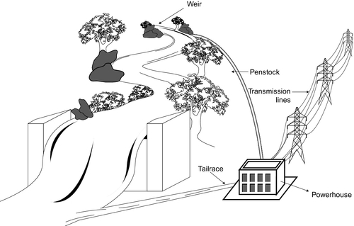
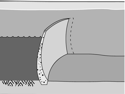
A run-of-river scheme is the simplest and cheapest hydropower project to develop. Since it requires no dam, a major constructional cost is avoided. Geological problems associated with dam construction (see next section) are avoided too. However, some sort of diversion structure will be required to direct water from the river into a canal called the headrace, which carries the water to a spot above the power house of the plant, exploiting the local topology to achieve the minimum drop in elevation (Figure 8.1). From here the water falls steeply through a pipe called the penstock into the power house and the turbines. (In smaller projects the headrace and penstock may be the same pipe.) The height of the penstock intake above the power house represents the head of water that is available for generating power in the plant. It is the pressure at the bottom of this head of water, dependent on the height of that head, that provides the force to drive the turbines. Having passed through the turbines the water is returned to the river at a point downstream of the diversion structure through another pipe called the tailrace. For large run-of-river plants the headrace can be tens of kilometers long.
The simplicity of the run-of-river scheme is attractive but it is also the main weakness of this type of development. With no dam to conserve water, the power plant must rely exclusively on the flow of water in the river. As this fluctuates, so will the amount of power that can be generated. Under drought conditions the plant will be able to generate no power, whereas when the river is in flood, much of the available water will have to be allowed to flow past the diversion system without being exploited. The same applies when power from the plant is not needed for the grid. Nevertheless, this type of project does have significant advantages besides cost, particularly because of the small amount of environmental disruption it causes.
Run-of-river hydropower plants are typically between 10 MW and 1000 MW in generating capacity. They could be larger, in theory, but in practice larger plants of this type have not been built. A series of run-of-river power plants along the same river can exceed 1000 MW in capacity.
Dam and Reservoir Projects
The alternative to the run-of-river is a dam and reservoir project. This will involve a major civil engineering undertaking: the construction of a dam.
The purpose of a dam is to create a reservoir of water that builds up behind it. The reservoir is essentially a form of energy storage system. Once created, the reservoir allows some measure of control over the flow of water in the river beyond the dam and consequently the flow through the turbines in the power house. Water can be conserved during periods of high flow and used up when rainfall is low. A dam can also be used for flood control. More recently, dam and reservoir hydropower systems have been used to help balance intermittent forms of renewable energy on the electricity grid.
If a dam is to be constructed, then a very careful geological survey of the underlying rock will be needed to identify any faults that might make it unstable or allow water to flow beneath it. Geological faults or unsuitable substrata need not prevent construction of a dam because they can be treated, but if they are only discovered during construction, or later, they are likely to result in massive additional costs and delays.
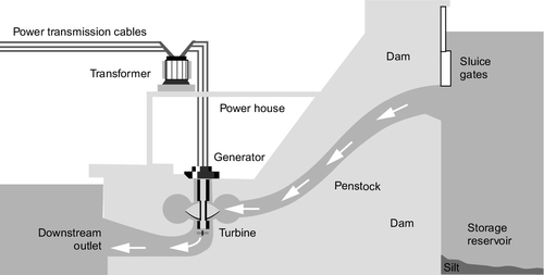
The layout of a dam and reservoir scheme is essentially the same as for a run-of-river plant. Water is extracted from the dam and carried though a headrace until it is above the power house where it enters the penstock and falls into the turbines. From the turbine hall it is then returned to the river through a tailrace. However, since the dam itself may generate the main head of water, the design can often be more compact than for a run-of-river plant and a headrace dispensed with Figure 8.2.
The construction of a dam is a complex engineering project. Water flowing down the river must be temporarily diverted or coffer dams must be erected to isolate part of the riverbed so that construction can take place. The size and complexity of dam construction means that this part of the project will account for up to two-thirds of total project costs.
While the dam forms the major part of the construction project, the reservoir behind the dam is likely to have the largest environmental impact. The lake created behind the Three Gorges Dam is 600 km long, but even small dams can create large areas of water with dramatic effects on the local environment.
Dam types
There are three principle types of dam used for hydropower projects: embankment dams, concrete gravity dams, and concrete arch dams. The simplest of these and the cheapest to construct is the embankment dam.
Embankment Dam
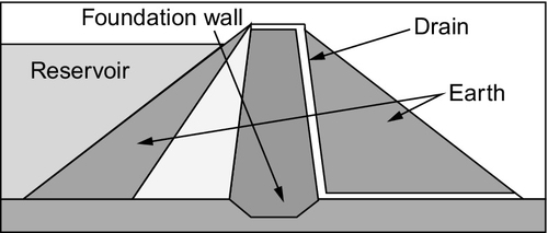
Embankment dams come in two principle varieties: earthfill embankment dams and rockfill embankment dams. An earthfill embankment dam is made by building a foundation wall that is embedded into the rock below the dam to prevent water flowing beneath it and then creating a core of impermeable clay on top of this (Figure 8.3). Above this the remaining structure is built from earth, normally from the surrounding area. It is the mass of earth and clay that holds the dam in place. A rockfill dam uses rock instead of earth, normally with an impermeable layer on the upstream face of the dam to prevent seepage through the porous core. However, both types of dam can tolerate controlled amounts of seepage.
Both types of embankment dam are vulnerable to overflow of water eroding the dam structure, so each must be provided with a spillway that can release water from the reservoir behind it if the water level becomes too high. These dams have shallow sloping sides to create a large mass and are usually employed in shallowly sloping valleys, creating relatively wide and shallow reservoirs.
Concrete Gravity Dam
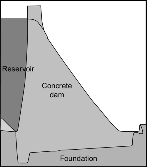
The second main type of dam is the concrete gravity dam. Like the embankment dam this relies on its mass to resist the pressure of water, but resistance may also be aided by the concrete structure being bedded into the underlying rock and, where possible, into the sides of the watercourse where it is constructed (Figure 8.4). Concrete dams cannot deform like embankment dams and are vulnerable to water passing beneath them, which may undermine the structure, so the integrity of the geological strata below the dam is essential.
A variant of the concrete gravity dam is the concrete buttress dam. This has a vertical upstream face but downstream it is supported by massive triangular buttresses built into the rock below. Such dams require less concrete than a concrete gravity dam since they use the buttresses to resist the water pressure.
Concrete Arch Dam
The final type of dam is the concrete arch dam. This deploys the principle of the arch to resist the pressure of water. An arch dam can only be built in a steeply sided rock ravine where both the sides of the ravine and the underlying substrata are sound. The arch is built on its back, bowing upstream, with the sides bedded into the rock faces of the side of the ravine (Figure 8.5). The concrete arch dam is the most precisely engineered of all dam types and requires less material than other types and where it can be built it is the strongest of dams.
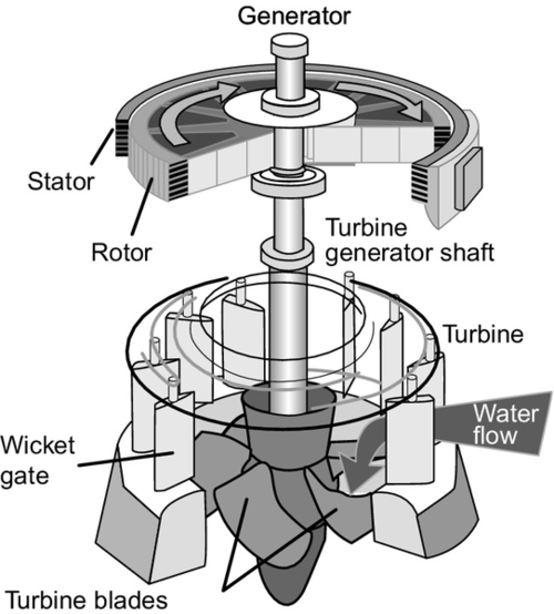
Hydropower turbines
The most important mechanical component of any hydropower-generating unit is its turbine. This is the device that converts the energy contained in the moving water into the rotary motion necessary to turn a generator and produce electricity. The hydraulic turbine is a simple, reliable, and well-understood component made from simple materials. Most turbines are made from iron or steel or cast from bronze or other alloys. In the past wood was commonly used too.
The history of the hydropower turbine is long. The earliest known, water wheels for grinding grain, were used by the Romans and were known in China in the 1st century. They were common across Europe by the 3rd century and could be found in Japan by the 7th century. The Doomsday Book of AD1086 records 5000 in use in the south of England. These early water wheels were made of wood. Iron was first used in the 18th century by an English engineer, John Smeaton.
Early water wheels were simple paddle wheels, the lower edge of which was placed into a flowing stream where the pressure of water against one side of the immersed paddle caused it to turn. This is the basis for one group of turbines in use today called reaction turbines. It was later discovered that more energy could be extracted by damming the water to create a head and using the pressure at the bottom of this head to create a jet of water that was directed against the paddles of the wheel. This principle led to the development of the second main branch of hydropower turbines, the impulse turbines.
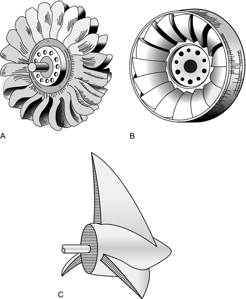
Modern turbines can be extremely efficient with the best converting 95% of the energy contained in the water into rotary motion. They can be stopped and started very quickly and are capable of operating reliably for many years. Large hydropower projects generally make use of one of a small number of turbine types, discussed in the following sections (Figure 8.6). Small hydropower plants utilize these same types but they can exploit a wider range of turbines including some extremely novel designs (see later).
Impulse Turbines
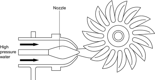
A tall column of water creates a high pressure at its base and if the water under high pressure is released through a fine nozzle it will create a high-speed jet of water. If this jet is directed onto a bucket-shaped paddle on a wheel it will generate an impulse that causes the wheel to turn. This is the basis for the impulse turbine.
The main type of impulse turbine in use today is the Pelton turbine, patented by the American engineer Lester Allen Pelton in 1889 (Figure 8.7). The Pelton turbine operates at its highest efficiency, 95%, when the speed of movement of the bucket on the wheel rim is half that of the water in the jet directed into it.
The Pelton turbine is generally used where a high head of water is available and the flow rate is low. For large hydropower plants they are normally preferred when a head height of more than 450 m is available, but they can be used for heads a low as 200 m. The maximum head for a single Pelton turbine is normally 1000 m. Beyond that the fall must be divided into two sections and more than one turbine will be required.
A simple Pelton turbine will have one nozzle but power output can be increased by using up to four nozzles directed at the same wheel. Most Pelton turbines are mounted vertically with a horizontal axis of rotation, but they can be mounted with a vertical axis so that the turbine lies horizontally. A key feature of all Pelton turbines is that they must operate in free air, not submerged. The turbine must, therefore, always be positioned above the water level at the bottom of the head of water being utilized for power generation.
The speed at which a Pelton turbine rotates will be determined by both the flow rate of water directed into its buckets and the load into which it is feeding. If the load falls, the turbine will speed up. This can be controlled by reducing flow through the nozzles. The optimum efficiency is achieved when the turbine is operating between 60% and 80% of maximum load.
A second type of impulse turbine available for high-head use is the Turgo turbine. This is similar to the Pelton in design, but whereas with the Pelton turbine the water jets are in the same plane as the turbine wheel, in the Turgo turbine the jet strikes each bucket from one side and then exits the turbine at the other side. The Turgo turbine can handle higher flow rates than the Pelton but is generally more difficult to construct. It is normally used for medium-head applications between those best suited to the Pelton and those more suited to reaction turbines.
Reaction Turbines
For heads of water below 450 m, a reaction turbine will normally be the first choice. This type of turbine must be completely submerged to operate efficiently. Whereas the impulse turbine harnesses the kinetic energy (and the momentum carried by its mass) of a jet of high-pressure water, a reaction turbine responds to the pressure (potential energy) created by the weight of water at the base of the head acting on one side of its blades.
There are several different types of reaction turbine. The most popular, accounting for 80% of all hydraulic turbines in operation, is the Francis turbine. This can be used in almost every situation, but for very low heads, propeller turbines and Kaplan turbines are frequently preferred.
Francis Turbine
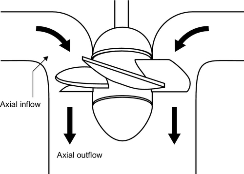
The Francis turbine was developed by James Bichens Francis around 1855. Its key characteristic is the fact that water changes direction as it passes through the turbine. The flow enters the turbine in a radial direction, flowing toward its axis, but after striking and interacting with the turbine blades it exits along the direction of that axis (Figure 8.8). It is for this reason that the Francis turbine is sometimes called a mixed-flow turbine. For it to operate efficiently, water must reach all blades equally and flow is controlled by a set of valves or gates that curl around the turbine itself in a spiral shape.
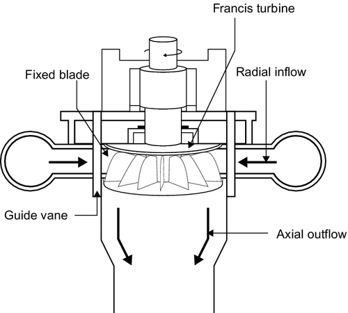
The blades of a Francis turbine are carefully shaped to extract the maximum amount of energy from the water flowing through it. Water should flow smoothly through the turbine for best efficiency. The force exerted by the water on the blades causes the turbine to spin and the rotation is converted into electricity by a generator. Blade shape is determined by the height of the water head available and the flow volume. Each turbine is designed for a specific set of conditions experienced at a particular site. When well designed, a Francis turbine can capture 90–95% of the energy in the water.
The Francis design has been used with head heights from 3 m to 600 m, but it delivers its best performance between 100 m and 300 m. Flow rate is often the limiting factor for a given head. As the head height rises, the size of the turbine must fall, making fabrication more difficult. High-head Francis applications, therefore, require a large flow to be successful. Conversely, for low-head applications the flow must be low or the turbine will become excessively large. It is for this reason that while the Francis turbine is the most versatile, different designs are generally used for both very high and very low heads.
Francis turbines are also the heavyweights of the turbine world. The largest, found at both the Itaipu power plant on the Brazil–Paraquay border and at the Three Gorges Dam in China, have generating capacities of 700 MW each.
Propeller and Kaplan Turbines
If the head of water becomes too low, the rotational speed of a Francis turbine falls and with it efficiency. For low-head applications an alternative turbine type is required and the most successful is the propeller turbine (Figure 8.9). A propeller turbine looks like the screw of a ship, but its mode of operation is the reverse of the ship’s propulsion unit. In a ship a motor turns the propeller, which pushes against the water, forcing the ship to move. In the hydropower plant, by contrast, moving water drives the propeller turbine to generate power.
Propeller turbines are most useful for low-head applications such as slow-running, lowland rivers. The head of water is typically 10 m or less. Their efficiency drops off rapidly when the water flow drops below 75% of the design rating, so plant designers often use multiple propeller turbines in parallel, shutting down some when the water flow drops to keep the remaining turbines operating at their optimum efficiency.
A variant of the propeller turbine is the bulb turbine, used for extremely low-head conditions. In this design the turbine is integrated with a water-tight generator and enclosed in a bulb-shaped container. The turbine rotor can have fixed or variable blades. Water flows into one end of the bulb-shaped container, called the nacelle, and out the other, with no change of direction. The use of the nacelle helps concentrate the flow to maximize energy capture. The bulb turbine has been used in tidal power plants.
There are cases where multiple turbines cannot easily be used. In these cases, an alternative called the Kaplan turbine has sometimes been utilized instead. This low-head variant of the propeller turbine was developed by Viktor Kaplan in 1915. Its primary feature is a set of blades that can be adjusted to maximize efficiency under different flow conditions. These turbines can operate at higher flow levels than conventional propeller turbines and are suited to heads between 10 m and 50 m. A variation of the Kaplan turbine is the diagonal-flow turbine that can operate at higher rotational speeds than the Kaplan and is suited to higher heads.
Deriaz Turbine
A further turbine available to hydropower plant designers is the Deriaz turbine invented by Paul Deriaz. This has blade shapes similar to a Francis turbine but these blades are adjustable and so they can be adapted to different flow rates. The Deriaz turbine is another mixed-flow turbine in which water enters from the size but exits along the turbine axis. It is best suited to head heights between 20 m and 100 m, in between the ranges of Francis and Kaplan turbines.
Generators
The turbine in a hydropower plant is connected directly to a generator to produce electricity, as shown in Figure 8.10. Generators for large hydropower turbines are normally synchronized to a grid at 50 Hz or 60 Hz and this controls the speed at which both the turbine and generator must rotate.
Turbine speed will vary with turbine type. For a Pelton turbine the typical rotational speed is 400–1000 rpm. Francis turbines typically rotate between 100 rpm and 1500 rpm. Propeller turbines, meanwhile, run at speeds between 60 rpm and 300 rpm. In each case the generator must be tailored to suit the turbine speed.
A synchronous generator cannot operate at any speed but instead must turn at one of a number of fixed speeds. Flexibility of generator rotational speed is achieved by varying the number of poles. The smaller the number of poles, the higher the rotational speed needed to achieve a given synchronization frequency. For 50 Hz operation a two-pole generator must rotate at 3000 rpm, while a 60 Hz machine must rotate at 3600 rpm. For eight-pole generators the necessary speeds would be 750 rpm and 900 rpm. Therefore, generators for slow-speed turbines require a larger number of poles.
While most large hydropower plants rely on synchronous generators of this type, an increasing number of smaller units are starting to employ variable-speed generators. These can operate at any speed, the latter being determined to optimize efficiency. Output from the generator is then converted to grid frequency using solid-state power electronic devices. The power-handling capabilities of the latter generally limit the generator size to tens of megawatts.
Small hydropower
Small hydropower plants are defined as much by regulatory regimes as by their inherent design features. Plants below a certain size usually qualify as new renewable generation and these are called small hydropower plants. The limit varies from country to country. In Sweden, for example, the upper size of a small hydropower plant that can attract support is 1.5 MW. In Italy the limit is 3 MW, in France 12 MW, in the United Kingdom 20 MW, and in Canada and the United States it is between 30 MW and 50 MW.
The global installed capacity of small hydropower plants is not known precisely but is probably around 50,000 MW, although it could be significantly higher. The potential for future development is equally uncertain but the International Energy Agency has suggested that there may be 150,000–200,000 MW capable of development.
The design of a small hydropower plant depends very much on its size. Those in the small hydropower category of Table 8.3 (1 MW to between 10 MW and 30 MW) will be approached in a similar way to a large hydropower project. At this size, dam construction is less likely to be cost effective but some sort of barrage may be employed. At the smaller end of the range off-the-shelf rather than site-specific turbines are also likely to be used. In most cases these will be the types discussed earlier for large hydropower schemes.
Mini- and micro-hydropower plants of less than 1 MW in size are likely to be approached differently. Here cost becomes the overriding concern and a range of novel techniques including the use of cheap pumps as turbines and inflatable barrages may be employed to keep costs down.
One major difference between large and small hydropower is the breakdown of head height into categories. For a small hydropower plant a head above 100 m will be considered a high head and any project with a head of this or higher will employ a high-head turbine such as a Pelton turbine. For very small projects a Pelton turbine may be used at even lower head heights. Projects with heads between 30 m and 100 m are classified as medium-head schemes, while anything under 30 m qualifies as a low-head plant.
Plant design will be much simpler in a small hydropower scheme. Most will be run-of-river (or run-of-stream) and any intake structures, where used, are likely to be rudimentary to keep costs low. For larger plants a weir may be employed. Others will take water directly without any type of barrage. In many cases the turbine generator will be placed directly into the waterway.
If water is extracted from the river or stream it may be carried some distance through the equivalent of a headrace, but more commonly it will be fed directly into a penstock-type conduit that carries it directly into the turbine. Penstock length can affect project costs significantly so this will be kept as short as possible.
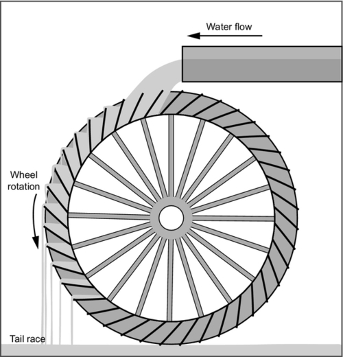
Turbine types for small hydropower schemes will depend on head height; Pelton turbines for high-head, Turgo and Francis for medium-head, and propeller and Kaplan turbines for low-head applications. Other turbines are also commonly used. These include the cross-flow turbine–a low-cost type of impulse turbine–the Archimedes Screw and the Gorlov turbine that is a little like a vertical-axis wind turbine that operates under water. Simple paddle-type water wheels are also common (Figure 8.11). For very small applications cheap pumps can be used in reverse to make turbine generators. These are known as pumps-for-turbines (PATs) and can be used with head heights of 13–75 m to build very cheap hydropower facilities. Small propeller turbines fitted with sealed generators can also be dropped directly into a stream to provide a hydropower-generating system.
While larger small hydropower schemes may use synchronous generators of the sort used in large plants, many small plants employ asynchronous generators that rely on the grid to help them control their speed of operation. In some cases these are simply motors being used in reverse to generate power. The efficiency of such small asynchronous generators is much lower than for large generators.
Small hydropower schemes tend to be relatively more expensive than larger schemes because costs of many of the components do not fall in line with size. The cost of a grid connection can become a large component of the small hydropower scheme and a feasibility study may take a large share of the budget. The extra cost can still be economical if the small hydropower scheme is supplying power directly to consumers where it will be competing with the retail cost of electricity rather than the wholesale cost. Small hydropower schemes can also be extremely effective in supplying power to remote communities far from a grid, especially when the alternative is diesel power.
Environmental considerations
The environmental effects of a hydropower project, particularly one involving a dam and reservoir, are significant and must be taken into account when a project is under consideration. What is going to be submerged when a reservoir is created? What effect will the dam or barrage have on sedimentary flow in the river? What are the greenhouse gas implications? Whose interests are affected? For a run-of-river scheme the level of disruption is likely to be lower but extensive environmental studies will still be required. In both cases all these issues must be addressed. Small hydropower schemes are rarely disruptive on the same scale as large hydropower projects and their impact is usually limited so that decisions can often be made at a local rather than a national level. Large schemes have the potential to affect regions and require much more careful scrutiny at regional or national levels.
This problem is not new. Humankind has been altering waterways for at least two millennia and some of the early structures still exist. Roman dams can be found in use in Spain today. In the past dams have been used to provide water for drinking and irrigation and to help control waterways. Only since the end of the 19th century has electricity generation been added to this list of uses.
While dams will always change the environment, in the past the changes wrought have generally been considered positive, providing an improvement in the living standards and conditions of the people affected. Greater environmental awareness coupled with some careless developments led to a change in perceptions toward the end of the 20th century and since then large hydropower schemes have become much more difficult to promote and build. This prompted work by the World Commission on Dams to look at what made a good and what made a bad hydropower project.
The work of the World Commission on Dams resulted in 2000 in the publication of Dams and Development: A New Framework for Decision Making.4 Since then a reappraisal of large hydropower has taken place resulting in greater acceptance of the need to develop waterways. In particular, the link between water projects and the standard of living of people affected has been recognized. This is particularly significant in Africa where hydropower development is far behind other continents and standards of living are often very low too.
So while it is recognized that a hydropower project, particularly a large one, will be disruptive, it is also recognized that it need not necessarily be destructive. Environmental changes will take place, people may be displaced, and habitats destroyed but all these effects can be handled sensitively so that, for example, displaced communities are given a stake in the project and much improved living conditions and inundated habitats are recreated alongside the area destroyed.
Environmental assessment
Today, to make a case for a major hydropower project, a thorough environmental assessment will usually be necessary and in most cases it will be mandatory. The effects of the project, including any necessary resettlement, effects on biodiversity, the potential for seismic activity, and the impact on areas downstream of the project, will all have to be evaluated. Such a study should include proposals for the mitigation of any negative effects of the development. In many cases, particularly where international lending agencies are involved, a project will not be permitted to proceed unless the environmental assessment is favorable. This is equally true of public sector and private sector projects.
Resettlement
The most divisive effect of any large hydropower project is likely to be the need to resettle people whose homes or communities will be destroyed. In building the Three Gorges Dam, the Chinese government moved 1.3 million people and more people might need to move if the reservoir banks become unstable. This represents one of the largest resettlement programs for a hydropower project, but even with much smaller numbers the result will be extremely disruptive for those involved.
Resettlement numbers can be large as in the case of the Three Gorges Dam, but how is one to judge if they are too large? One way of at least comparing projects is to determine the number displaced for each megawatt of generating capacity installed. For the Three Gorges Dam this ratio was 71. The Kedung Ombo Dam in Indonesia, a 29 MW project that led to the displacement of 29,000 people, had a ratio of 1000 people/MW. In contrast, the Grand Coulee Dam built in the 1930s in the United States had a ratio of 2.
If people are to be displaced then a rule of thumb for modern developments is that they should be better off economically afterwards than before. More than that, people being moved should have a large say in where they are moved to and a stake in the project. If the project can provide wide community benefits then people will support it. If not, then development should be questioned.
The situation becomes more difficult when whole communities and their cultural and religious sites are likely to be destroyed. It is sometimes possible to move such sites; the most high-profile example of this is the rebuilding of an Egyptian temple before inundation of the Nile behind the High Aswan Dam in Egypt. However, cultural and religious beliefs may make such a solution unacceptable. In many cases, particularly in remote parts of the world, such considerations are all too easily ignored.
Biodiversity
Even if a dam and reservoir does not displace many people it can still have an enormous impact if it affects a large area. The relative impact in this case can be crudely assessed by calculating the area inundated for each megawatt of generating capacity. This ratio for the Three Gorges Dam was 317 ha/MW while for the Grand Coulee Dam it was 5 ha/MW. Meanwhile, the Kompienga Dam in Burkina Faso achieved the score of 1426 ha/MW, the highest of any recent project. Again this is only a broad indication of the effect since it will also depend on the type of terrain that is being submerged. However, large, shallow reservoirs will always have more impact by this measure than deep, narrow ones.
The greatest danger to biodiversity is that a project will destroy the home of an endangered species. Since hydropower projects take a long time to develop, it is possible to create a new habitat to replace the one that is threatened while work continues on dam construction. This can be relatively straightforward for plant species but can be much more difficult for animal species. However, it is feasible. Indeed, some older projects are now introducing managed habitats that were not considered when the plant was initially built.
The effect of dam and reservoir construction on aquatic species is less obvious but can be equally dramatic. In France several rivers no longer support salmon as a consequence of dams, and in China the Yangtze dolphin was declared extinct in 2006, partly as a consequence of hydropower developments along the river that prevented its movement.
The water in deep reservoirs can become deoxygenated, affecting aquatic life that might otherwise live there. On the other hand, the creation of a reservoir can provide new opportunities for fish species and large reservoirs can allow fish farms to develop, creating a new industry that did not previously exist.
Geological Effects
There is a growing body of evidence that the construction of dams and inundation of reservoirs can generate seismic activity in the underlying strata as a result of the pressures generated at the surface. Such effects are normally only found with large dams, over 100 m high. The activity is generally short-lived but in some cases it can persist. And earthquake in Sichuan province in China in 2008 has been linked to a dam. This earthquake caused the loss of 80,000 lives.
Another danger is of landslips in the region around the reservoir. A case of this type in Italy in 1983 caused a reservoir to overtop, leading to the loss of 2600 lives. Such landslips are not only potentially fatal, as in this case, but they also reduce the volume of the reservoir and therefore its utility.
Sedimentation and Downstream Effects
All rivers carry a load of small particles that are borne downstream with the water. When a river is dammed, this load of sediment will often simply settle in the bottom of the reservoir and slowly fill it up. The reservoir for the Sanmen Gorge hydropower plant on the Yellow River in China lost 40% of its volume to sediment in four years. While this is a dramatic case, most reservoirs have to deal with this problem on some scale.
Normally sediment deposition will reach a steady state with enough sediment being carried past the dam to balance that being deposited each year. It is sometimes possible to wash sediment away periodically by opening the sluice gates of the dam. However, sediment is made of abrasive particles and its passage through the plant’s turbines will cause wear that may eventually lead to the need for repair or replacement.
Many of the most important environmental effects of sediment deposition are felt downstream of the dam. One immediate effect of loss of sediment is to increase erosion immediately below the dam site. More dramatic is likely to be the effect of loss of sediment on downstream habitats that rely on it. When the Aswan Dam was built on the Nile River it prevented vital sediment reaching the Nile delta. This sediment was the source of the delta’s fertility and its loss led both to delta erosion and to a rapid increase in the use of artificial fertilizers. Problems in the Black Sea with algae have also been linked to loss of sedimentary material as a result of dams on rivers such as the Danube.
Against this, a dam on a major river such as the Danube or the Yangtze can help control flooding, making downstream regions much safer. It can also make the river navigable upstream, which can be a benefit for local communities.
Greenhouse Gases
Hydropower projects are generally classified among the power generation schemes with the lowest greenhouse gas emissions. Typical greenhouse gas emissions are 10–13 kg/MWh, similar to that of wind power plants. Not all hydropower schemes are low emitters, however. Some can generate significant quantities of methane, a potent greenhouse gas.
Methane is produced when organic material collects in the bottom of a reservoir where the water is deoxygenated. Under these conditions anaerobic digestion takes place releasing methane gas. To prevent this, project developers should try to remove as much organic material as possible from the region to be inundated before submersion takes place by felling trees and clearing undergrowth where possible. Even so it will be impossible to remove everything.
The Canadian utility Hydro Quebec, which has studied this effect, has found that methane production from reservoirs normally follows a predictable cycle. Production peaks between 3 and 5 years after the reservoir is filled. After 10 years emissions are no greater than for natural lakes. However, there have been cases where much higher levels of methane emissions have been detected.
Interregional Effects
Dam construction can lead to political disputes when rivers cross national boundaries. For example, the damming of the Euphrates River in Turkey has reduced water flow through Syria and Iraq and this has led to frequent disputes. Reduced water flow when water is taken upstream for irrigation or drinking is one problem. Others may relate to sedimentation issues discussed earlier. In all cases, however, friction is likely unless great care is taken with such developments.
Hydropower and intermittent renewable generation
The amount of electricity generation from sources such as wind energy and solar power is increasing in all parts of the world. The output from this type of power generation plant is intermittent, and this causes problems for grid operators who must maintain their grids in balance while absorbing all the energy from these sources when it is available.
The traditional solution to this balancing problem is to maintain fossil fuel–fired plants on standby so that they can be brought into service as the renewable sources fail. Typically some form of gas turbine–based plant will be used to provide this backup. However, where hydropower capacity based on dam and reservoir plants are available, these can often provide both a faster-acting and cheaper means of maintaining the grid in balance.
Pumped storage hydropower plants have provided an energy storage and grid support service for many years (see Chapter 10 on energy storage), but normal hydropower schemes can provide the same service so long as they are operating within their safety limits. A reservoir that is near flood levels will have to lose water whether power is needed or not, and one that is emptied during a dry season may not be able to generate. At other times, however, the plant should be able to stop and start as necessary. Grid support of this type can earn a power plant additional revenue and, as renewable generating capacities increase, hydropower is likely to be seen as increasingly important.
Cost of electricity generation from hydropower plants
Hydropower plants are generally considered to be capital-intensive power projects because most of the cost is associated with the construction of the plant and very little with its operation. This means that large amounts of funding must be available at the outset. In the past the high cost of building a hydropower plant was often borne by the public sector, but since the liberalization of electricity markets that started toward the end of the 1980s, it has often fallen to private sector companies to fund them, something that they have often been reluctant to do.
Some major schemes are still funded by the public sector and others are funded through financial-support mechanisms such as the World Bank. Increasingly, too, private investment is finding its way into hydropower. However, financing is often complicated by the fact that at least some of the benefits of a new hydropower project, particularly in the developed world, will accrue to the government. These benefits include flood control and the supply of irrigation and drinking water.
Another factor that affects the economics of hydropower is the long life that can be expected from a well-designed project. While most power plants have useful lives of 30–40 years at most, a hydropower plant can continue to operate for over 100 years provided the turbines are maintained and periodically replaced. However, financing of a project is unlikely to be possible over 100 years, so costs will be weighed heavily on the early years of the project. Once the cost of loans needed to build a hydropower plant have been paid, the cost of electricity from the plant is likely to be as cheap or cheaper than virtually all other sources.
The breakdown of costs for a hydropower plant suggests that typically 60–70% of the total is accounted for by the civil works. Equipment only accounts for 25–35% while engineering and consultancy takes the remaining 5–10%. Since the civil engineering portion of the project will involve considerable labor costs, overall costs will vary with these costs. Labor costs in some regions are likely to be much lower than in others.
Actual capital costs for hydropower plants vary widely but typical costs, based on published figures for recent plants, are between $1000/kW and $2000/kW. Many of these plants have been built in developing countries where labor costs tend to be lower than in developed countries. The U.S. Energy Information Administration (EIA) has estimated that the cost of a new 500 MW hydropower plant in the United States, commissioned in 2011 and entering service in 2015, would be $2134/kW, just outside the upper limit of the preceding range.5
Small hydropower plants tend to cost more than the larger projects because many of the costs do not scale with size. Typical costs are from $1500/kW to as much as $5000/kW. However, the actual costs of such projects will depend on both size and the type of technology being used. Very small schemes based on pumps as turbines could be a much lower cost.
Even with relatively high capital costs, hydropower can offer a low cost of electricity option. For example, in the United States, the EIA estimated that the cost of electricity from a new hydropower plant entering service in 2017 would be $89.9/MWh. Of the common technologies this was only undercut by a natural gas combined cycle power plant without carbon capture and storage. This price will be based on some form of financing and loan repayment. However, for plants in the United States that have paid off their loans, generation costs are estimated to be between $20/MWh and $40/MWh, undercutting virtually any alternative source.6