
Sulfuric acid
Abstract
Sulfuric acid production has for years been a metric used to determine a country’s industrial development. This chapter provides a complete analysis of the two main production methods: lead chamber and contact processes. We follow the chronological development and technical reasoning behind the use of lead chambers, from the original chambers to the final process. Next, a complete mass- and energy-based analysis is presented. For the contact process, we focus on the analysis of the performance of multibed and fixed bed reactors, and present the energy integration within the process, using MATLAB to simulate the operation. Finally, transport phenomena-based analysis and mixture thermodynamics are explored to evaluate the operation of absorption towers. Examples requiring process simulators are proposed in the end-of-chapter exercises.
Keywords
Sulfuric acid; SO2 oxidation; fixed beds; absorption tower; lead chambers
7.1 Introduction
History: The discovery of sulfuric acid is attributed to the Persian alchemist Abu-Beskv-Ahhases in the 15th century. However, it was already known long before, back in the era of Albertus Magnus (1193–1280). During the 15th century in Germany, sulfuric acid was produced by heating iron(II) sulfate heptahydrated (green vitriol), which inspired the name “oil of vitriol.” The process was reported in the 16th century. The properties of the oil were first described in 1570 by Pornaeius. Later, Johann Van Helmont (c.1580) obtained it via dry distillation of green vitriol (hydrated iron(II) sulfate, FeSO4·7H2O) and blue vitriol (hydrated copper(II) sulfate, CuSO4·5 H2O). The chemical basis for the lead chamber process was introduced by Andrea Libavius in 1595:
The reactor for running this process was developed in Birmingham, England, in 1746 by John Roebuck. The breakthrough in the production process consisted of substituting the glass units used before, and increasing the conversion up to 78%. For years this process was improved by recovering the catalyst using Gay-Lussac and Glover Towers, and increasing the concentration of the product. By 1831, a patent was issued that described the catalytic oxidation of SO2 over platinum, the contact process. This process made it possible to increase the reaction yield from 70% to 95%. Although the initial catalyst was platinum, others were tested. In 1913 BASF was granted a patent for the use of vanadium(V) oxide (V2O5), which became the catalyst of choice due to its lower cost and resistance to poisonous species. In 1960 a further evolution was patented by Bayer for a process involving a double absorption (double catalyst) process. For years sulfuric acid production has been used as a metric for the industrial development of a country; it has a global production volume above 150 Mt/yr.
Raw materials: Sulfur-based species are typically used as raw materials for sulfuric acid production, from sulfur, copper, iron, and zinc sulfides, to industrial gases like SO2 and H2S. The Claus process can transform these gases into elementary sulfur as a raw material for sulfuric acid production (see Chapter 5: Syngas). Sulfides are raw materials for the metals, while sulfur is a byproduct. However, for iron(II) sulfide, both elements need to be considered as equally important for the profitability of the process. Pyrite complexes are species that are found together with iron sulfide and other sulfides such as those from copper, zinc, and/or lead. Furthermore, other elements such as copper, selenium, gold, and silver can be found in small amounts. Table 7.1 shows the typical mass composition of pyrites and complexes. Finally, other sulfur-based species from refineries can also be used. In particular, pyrites are an interesting raw material.
Table 7.1
Pyrite and Complex Compositions
| % by Weight | ||
| Species | Pyrite | Complex |
| S | 46.0–50.0 | 44.0–48.0 |
| Fe | 41.0–45.0 | 36.0–40.0 |
| Cu | 0.4–1.0 | 0.4–1.3 |
| Zn | 0.2–2.3 | 3.0–8.0 |
| Pb | 0.5–1.3 | 2.0–6.0 |
| Ag | 0.3–0.6 | 0.3–0.7 |

Applications: The industrial applications for sulfuric acid are based on two properties:
• It is a strong acid when in water solution; concentrations below 5% by weight are needed for the second proton to be dissociated.
• It is a dehydration agent when concentrated over 80% by weight (and above 95% is preferable).
Furthermore, it is relatively cheap. It is typically commercialized in long-term contracts from large production and consumer companies. The most important consumers are phosphoric acid producers, who typically allocate their facilities in the vicinity of the sulfuric acid production plants. Moreover, it is a reagent used in the production of numerous other chemicals such as explosives, synthetic fibers, fertilizers, etc., and in metallurgy for purification processes for sugar dehydration or concentrated nitric acid production.
Health and safety issues: Sulfuric acid is a strong acid when in dilute solution. It attacks the skin, eyes, and mucoses. Furthermore, when in contact with metals, a large volume of hydrogen can be generated. It reacts exothermally with water, dehydrates and even burns organics, and reacts with other reductants as well. Oleum and sulfur trioxide (SO3) also react energetically with water.
Global production: The production of sulfuric acid has increased from 130 Mt to over 220 Mt in the last 40 years due to the increased consumption of phosphate and sulfate fertilizers. It is typically sold as solutions of 98–99% by weight as produced, but it can be commercialized as solutions of SO3 in sulfuric acid, also known as oleum. If water is added, additional sulfuric acid can be produced. It is typically shipped in 200,000 t container ships. It is stored at room temperature and in carbon steel tanks; the tanks are cylindrical with a conic roof, and are in concrete structures re-covered with stoneware bricks. They need to have a pipe to alleviate pressure and allow any generated hydrogen to leave, and for loading and unloading purposes. The price is usually stable (around $50/t), but in 2008 it reached $400/t. Current prices are around $100/t. Fig. 7.1 shows the distribution of production by region.

Chemical properties: The water–sulfuric acid system has a maximum boiling point azeotrope at 98.5% and 336°C that can easily be overcome in the production process. While diluted it is a strong acid capable of attacking all non-noble metals but lead, which can handle 80% acid at 90°C; concentrated solutions have a small acid constant and can be stored in carbon steel. There is a relationship between the concentration and the density up to 97%. Commercial concentration is close to freezing point.
Example 7.1
Fill in Table 7E1.1.

Solution
Definitions (°Be=degrees Baumé):

1. 65%
Using the tables in Perry and Green (1997) we compute the density at 15.6°C.
So, for 15.6°C we have ρ=1.5573 g/cm3.


2. 60°Be
Using the definition above we compute the relative density and the density of the sulfuric acid:
We interpolate that value in density tables as seen in Table 7E1.2.
Thus, with 1.7041 g/cm3, the mass fraction is 77.6%:
3. We cannot longer used °Be units. In 100 kg of mixture we have:
SO3 20 kg→20×98/80=24.5 kg of acid can be produced out of it. Thus, 104.5 kg of acid are potentially available in total, although only 80 kg are real. To compute the total SO3, we have the SO3 free, plus that in the acid.
4. ![]()
Therefore, in 100 kg, 65.16 kg are SO3, and the rest (34.84 kg) sulfuric acid. Thus the potential sulfuric acid in the solution is computed as (Table 7E1.3):
Table 7E1.2
| g/cm3 (%) | 15°C | 20°C | 15.6°C |
| 77 | 1.6976 | 1.6927 | 1.6970 |
| 78 | 1.7093 | 1.7043 | 1.7087 |


7.2 Pyrite Roasting
In this analysis it will be assumed that the mineral consists of sulfur and iron alone in the form of pyrite (FeS2) or pyrrhotite (Fe7S8). The reactions that take place are the following:

The global reaction is computed as:
This results in:
Pyrites lose moisture up to 100–110°C, but from 415°C onwards, one of the labile sulfur atoms is detached and it burns, as in reactions (5) and (6). Therefore with oxygen available, we produce FeS as slag:

If the combustion of the mineral is not complete, the FeS2 transforms into FeS as in the reactions above. If all of it is burned, the FeS2 produces Fe3O4 as in reaction 3. The mechanism is as follows:

For the combustion to be efficient, the lower the temperature, the more oxygen required. We need 150% excess at 680°C, but only 115% excess at 700°C. The sulfates produced at different stages decompose to oxides over 900°C. The type of mineral determines the melting temperature. Furthermore, SO3 in small amounts can be produced. It is typically neglected in the analysis. The production is due to reactions such as:
Both are slow and favored at lower temperatures. The SO3 can generate ![]() (Table 7.2).
(Table 7.2).
Table 7.2
| Rotary and mechanical furnaces can process particle sizes up to 10–12 mm. | |
 |
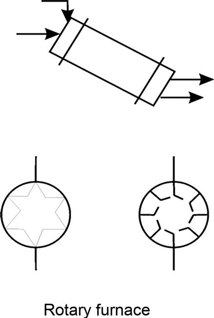 |
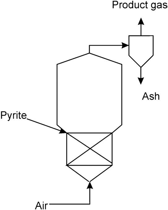
Flash Furnaces: The pyrite is fed from the top and the air from the bottom. Small particle sizes are required. The high operating temperatures result in the vitrification of the ash. Arsenic remains inside and iron cannot be recovered.
|
Fluidized beds: These allow processing of different types of particles with good heat recovery. Arsenic remains in the ash.
|


Gas cleaning: The product gas does not only contain the SO2, which is useful for sulfuric acid production, but also dust, that must be eliminated, arsenic and moisture. Dust is typically removed by gravity using colliders, cyclones, centrifuges, filters, or electrostatic precipitators. Moisture may become a problem since it generates sulfuric acid before the converter; this will corrode the catalysts and the pipes. Finally, arsenic oxides must be eliminated. CaO can be used to absorb arsenic, generating Ca3(AsO4)2. Alternatively, we can eliminate the arsenic oxides using a Tyndall box, where Fe(OH)3 is sprayed over the gases to remove the arsenic oxides as per the following reaction:
7.3 Sulfuric Acid Production
7.3.1 Lead Chamber Process: Homogeneous Catalyst
This process is no longer in use. However, it was the first one on the market and its evolution is a good example of process design. The first facility in the United Kingdom was installed in 1749 in Scotland, and it consisted of only the lead chambers. By 1772–77, based on Lavoisier’s discovery of the sulfuric acid formula, it was shown that niter was not a component of the acid; it was thought to be a catalyst. In 1827 Gay-Lussac introduced the tower that was named after him; it was designed to recover the nitrogen oxides that were lost with the gases. However, this tower was not used until 1859, when Glover introduced a new tower (a denitrification tower) to recover the catalyst from the liquid produced in the Gay-Lussac Tower, so that the sulfuric acid is denitrified. This process is only capable of producing low-concentration sulfuric acid. The process consists of three stages, as seen in Fig. 7.2 (Lloyd, 2011).

In plants up to 1920, niter pots were used to produce in situ the HNO3 used as catalyst. The gas was passed through a niter oven where NaNO3 and concentrated H2SO4 were heated. Later, an ammonia oxidation unit was used (see Chapter 6: Nitric acid, for nitric acid production from ammonia).
1. The SO2, impure with other gases, is processed through a dust chamber before being fed to the Glover Tower for denitrification. The tower is a cylinder of 12–14 m of diameter, whose walls are covered by Volvic rock, volcanic rock, resistant to acids. The outside surface is covered by a thick lead layer. From 1 m to 1.5 m from the base up to three fourths of its height, it is filled with a porous acid-proof packing. The lower limit is hydraulically sealed with the acid to avoid gas leaks. The hot SO2 is fed to the lower part of the Glover Tower. From the top, a liquid mixture of diluted sulfuric acid (53°Be) rich in nitrous gases (NO+NO2) from the Gay-Lussac Tower is sprayed inside, the nitrous vitriol (sulfuric acid with NO and NO2 dissolved). Nitric acid is also fed in as makeup. Part of the SO2 is oxidized into SO3, and it is dissolved into the acid solution to obtain the so-called Glover acid, a solution of 78% H2SO4. The process is described by the following reactions:

Thus, the sulfuric acid is denitrified in the tower. The nitrous vapors rise, acting as catalysts for the oxidation of SO2. The acid, as it descends, gives up the water and cools down the gases from the furnace. These gases mix with the steam and the nitrous vapors and are sent to the first lead chamber through a lead pipe located at the top of the tower.
2. From the Glover Tower, a mix of gases including sulfur dioxide and sulfur trioxide, nitrogen oxides, nitrogen, oxygen is transferred to a chamber internally covered by lead, where it is sprayed with water. The lead chambers are large tanks in the form of a truncated cone (100 m long, 15 m high, and 25 m wide) whose walls are made of lead supported by a wood structure. The walls and the bottom constitute a hydraulic seal where the produced sulfuric acid is collected. From the roof of the chambers, a fine spray of water is fed to dissolve the SO3 obtained in the chambers. The sulfuric acid, formed in the series of reactions presented below, condenses on the walls and is gathered at the bottom of the chambers:

The unconverted gases are fed to the second chamber and so on. Each chamber is smaller than the previous one. There can be from three to six chambers. The sulfuric acid produced has a concentration ranging from 62% to 68% H2SO4. It is called chamber acid. Finally, the gases are fed to the Gay-Lussac Tower.
3. The unconverted gases are washed with cooled concentrated acid from the Glover Tower in the Gay-Lussac Tower. The nitrogen oxides and the sulfur dioxide are dissolved in the acid, regenerating the nitrous vitriol that is sent to the Glover Tower. The unabsorbed gases are released to the atmosphere.
N2O3 is formed from NO and NO2. The catalyst losses are small: 5–8 kg of HNO3 per t of H2SO4.
The acid produced using this method can be concentrated from 78% (the typical concentration exiting the Glover Tower) using a cascade of silica dishes or by using the Gaillard process. The first method concentrates the sulfuric acid step-by-step in each dish. The Gaillard process consists of spraying the sulfuric acid inside a Gaillard Tower (diameter: 6–15 m; height: 10–20 m). The spray is put in countercurrent with hot gases from a coke furnace so that water is evaporated, concentrating the acid up to 92%. The hot gases are further processed in another tower where dilute acid is also sprayed. Next, the gases are fed to a precipitator where lead bars are used to maintain a high potential so that the mist of acid droplets is recovered.
7.3.2 Intensive Method
This method is based on the fact that if the concentration of sulfuric acid is above 70%, the use of lead chambers is no longer needed, and Fe is enough to handle the streams (which reduces the capital costs). The acid from the chambers is recycled and sprayed to increase the concentration. A number of modifications are carried out based on the lead chamber process (see Fig. 7.3):
• The production from the chambers is mixed with the stream that sends the nitrous vitriol from the Gay-Lussac Tower to the Glover Tower.
• To increase the concentration, the acid from the chambers is recycled to them.

As a result, the intensive method produces sulfuric acid with a concentration of 78–92%. Throughout the following examples we analyze the process for the production of sulfuric acid based on the lead chambers. The case study is based on the one in Houghen et al. (1959). Fig. 7E2.1 shows the flowsheet. In Example 7.2 we analyze the pyrite roasting process, in Example 7.3 the Glover Tower, and in Example 7.4 the lead chambers and the Gay-Lussac Tower.

Example 7.2
Mineral (100 kg/s) consisting of 85% pyrite (FeS2), 13% inerts, and 2% H2O is roasted in a furnace to produce SO2. Air at 25°C and 760 mmHg with a relative humidity of 30% is used. The gas product exits the furnace at 450°C with a composition of 8.50% SO2, 10.00% O2, and 81.50% N2. Only 0.5% of the initial sulfur goes with the slag. The slag exits the furnace at 450°C. Compute the air needed for the process and the heat losses in the furnace. (Fig. 7E2.1)
Solution
Complete roasting of the pyrite follows the reaction below:
However, the sulfur that is lost in the slag is only partially roasted:
The air fed to the furnace has a certain amount of water, and Pv (25°C)=23.76 mmHg. Therefore, per mol of air, the amount of water is computed as:
The slag consists of the inerts, the FeS, and the Fe2O3:
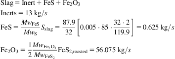

The slag composition is given in Table 7E2.1.
Using the stoichiometry of the reaction and the amount of Fe2O3 and FeS produced, we can compute the sulfur dioxide, and with it, the dry gas composition:

The nitrogen comes directly from the air fed. Thus, the air fed to the system is as follows:

Together with the mineral (100 kg/s), a flowrate of 496.9 kg/s of air is fed to the furnace.
The moisture that accompanies the gas product is given by that in the air plus that in the mineral:
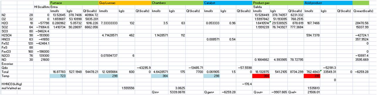
The total flow of product gases is 527.2 kg/s, the slag is 69.7 kg/s, and the total product flow is 596.9 kg/s. The energy balance is given as follows:

Assume that the slag has a heat capacity of 0.16 kcal/kg. Table 7E2.2 summarizes the operation of the furnace.

Example 7.3
The product gas from the furnace is fed into the Glover Tower. Fifteen percent (15%) of the SO2 is transformed into H2SO4. The Glover Tower also receives a flow rate of 600 kg/s from the Gay-Lussac Tower; it consists of 77% H2SO4, 22% H2O, and 1% N2O3. A stream of 1.5 kg of HNO3 with a composition of 36% is fed as makeup, and from the lead chambers a stream of 175 kg/s of H2SO4 with a composition of 64% is also fed to the Glover Tower. The product from the Glover Tower is sulfuric acid 78%. Compute the composition of the gas that will be sent to the lead chambers and the cooling needs so that the product acid is at 25°C. The gases from and to the lead chambers are at 91°C.
Solution
The conversion of SO2 to H2SO4 is 15%. Assume that the reaction taking place is as follows:
We compute the gas products and the sulfuric acid produced:

The sulfuric acid that exits the tower is computed using a mass balance:
Out of the total liquid stream, sulfuric acid represents 78% by weight; thus, the water that accompanies it can be computed as:

Next, a balance to water is performed. The reactions of the decomposition of the nitric acid must be accounted for. Furthermore, to compute the gas product, the decomposition of the N2O3 is also considered:

We assume that the conversions of these reactions are 100% because nitric acid is not exiting with the products:


Performing a global mass balance to the tower we have the amount of gas products:

Next, performing a mass balance to water, we compute the water that leaves with the gases (Table 7E3.1):

Table 7E3.1
| kmol/s | kg/s | |
| N2 | 13.526 | 378.741 |
| O2 | 1.599 | 51.193 |
| H2O | 1.641 | 29.539 |
| SO2 | 1.199 | 76.744 |
| NO | 0.166 | 4.994 |
The energy balance is performed considering the formation of solutions of sulfuric acid and NOx:

Table 7E3.2 summarizes the results of the mass and energy balances.
Example 7.4
The acid leaving the Glover Tower, free from nitrogen oxides, is partially sent to the Gay-Lussac Tower. The rest is collected as product. The gases from the lead chambers are sent to the Gay-Lussac Tower. Determine the acid produced in the facility, the water added to the lead chambers, and the composition of the residual gases from the Gay-Lussac Tower.
Solution
The total amount of sulfuric acid produced in the facility is the sum of that produced in the lead chambers and that produced in the Glover Tower. This is the one that must leave the facility to avoid buildup. The acid produced in the Glover Towers was determined in Example 7.3. The acid produced in the lead chambers is in the data from the problem. Furthermore, the acid produced from the facility has the same composition as that from the Glover Tower. Thus:

What follows is the analysis of the lead chamber operation.
To determine the water added to the chambers, we perform a molar balance to the entire process:

This is the reaction that takes place in the lead chambers:
The product is a flowrate of 175 kg/s with a composition of 64% by weight. Thus, the composition of the exiting gas is computed based on the stoichiometry in the chambers:

The molar balance to water that exits with the gases is calculated as follows:

The energy balance to the lead chambers is as follows:

where
The results are summarized in Table 7E4.1.

Now we look at the analysis of the Gay-Lussac Tower.
The gas exiting the chambers is fed to the Glover Tower. It is dry gas since the acid is a well-known dehydrating agent. Thus, the gas product from the tower is computed as shown below.
The SO2 exiting the tower is that which has not produced sulfuric acid:
The oxygen in the outlet gases is computed as follows. Oxygen enters with the air and is produced in the decomposition of HNO3. Moreover, it is consumed in the furnance and in the production of sulfuric acid:
Alternatively, we can determine the oxygen in the gases from the total amount exiting the chambers minus that needed for the regeneration of the catalyst.
The NO in the gas is that entering with the HNO3. Alternatively, we can compute it as that from the lead chambers minus that needed in the regeneration of the catalyst:
Finally, we perform an energy balance to the Gay-Lussac Tower as before:

The results are summarized in Table 7E4.2.

7.3.3 Contact Method: Heterogeneous Catalysis
7.3.3.1 History
This method was first described by Peregrine Phillips in 1831 when the patent was issued. It consisted of the oxidation of sulfur dioxide into sulfur trioxide and its absorption in water. This method was not widely used for over 40 years due to the lack of demand and the slow progress of technology necessary to work with pure gases. A few years later, in 1875 Clemens and Winkler showed that the SO2 and the O2 should be put into contact with the catalyst in stoichiometric proportions. By 1898 BASF had already evaluated several catalysts, from the original platinum to V2O5, which is the catalyst of choice today. The process allows high-purity sulfuric acid production. The first facility in the United States did not use water directly to absorb and hydrate the SO3, but sulfuric acid (King et al., 2006).
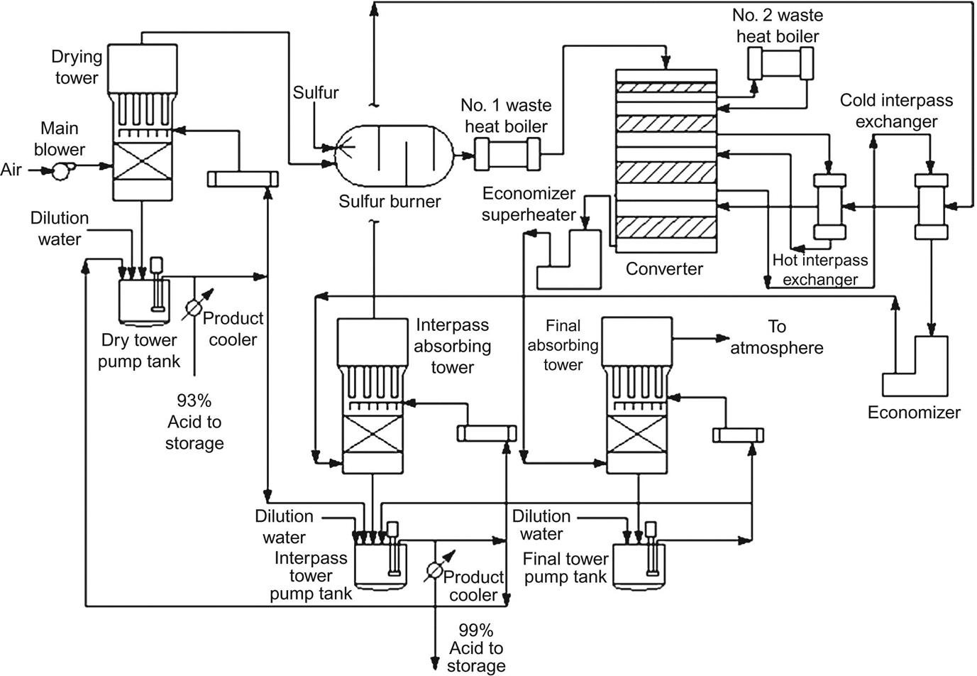
7.3.3.2 Process description
The process consists of three stages: sulfur burning, catalytic oxidation of SO2, and SO3 hydration. Fig. 7.4 shows a scheme of the layout of the plant. Note the size of the units and the pipes that connect them. There are two main alternatives: single-stage or double-stage absorption. Figs. 7.5 and 7.6 show each of them, respectively. We can use sulfur or pyrite as raw material in any of the processes. The disadvantage of using pyrite—in addition to the fact that it contains arsenic—is that the dust, arsenic, and antimony must be treated, which reduces the global yield of the plant. Furthermore, the dust can never be completely removed. Thus, the energy balance is better for sulfur-based plants.

1. Solid sulfur storage; 2. Sulfur melting; 3. Liquid sulfur filtration; 4. Liquid sulfur storage; 5. Air filtration and silencer; 6. Air dryer; 7. Sulfur combustion with two distinct burners with individual air supplies; 8. Steam, water storage, boiler; 9. Converter; 10. Intermediate absorber; 11. Final absorber; 12. Chimney; 13. Heat exchangers, economizers, heaters. Courtesy of Outotec OYJ with permission.

7.3.3.2.1 Sulfur combustion
The sulfur is received as a solid. It is melted and clarified before storage. Next, the clean sulfur is burned with air to produce sulfur dioxide. Fig. 7.7 shows a photograph of a typical burner. This air needs to have been previously treated to remove dust and humidity. The air is filtered and sent to a drying tower where it is washed with sulfuric acid (95–96 wt%) to remove the humidity—air moisture is responsible for corrosion in pipes and towers. Typically the dry air has a composition of 21% oxygen and 79% nitrogen. The reaction that takes place is the following:

The reaction is highly exothermic, so the exiting gas is at a high temperature. The final temperature depends not only on the ratio of oxygen to sulfur, but also on the heat loss due to radiation. Only a fraction of the oxygen is used to burn the sulfur. The rest is needed at a later stage in the converter. The gas composition from the sulfur burner depends on the oxygen-to-sulfur ratio.
7.3.3.2.2 Catalytic oxidation of SO2
For the reaction to progress, the feed to the converter has to be cooled down to 420–450°C. This is achieved using a boiler to produce steam. The gas stream containing the SO2 is filtered to remove the dust so that dry gases containing 7–10% SO2 are fed to the converter. The lower bound corresponds to pyrite-based facilities and the upper bound is common for sulfur-based ones. The stream composition with regards to oxygen is 11–14%. Thus, the typical ratio between O2 and SO2 is 1.7. In the converter, SO2 reacts with the oxygen already in the gas phase to produce sulfur trioxide:
There are two basic designs: the multibed reactor and the tubular packed bed.
Multibed reactor: This consists of a number of beds using Pt or V2O5 as catalyst, operating adiabatically from 400°C to 600°C. Current converters are made of stainless steel 304 or 321. The use of these materials, although more expensive, allows thinner walls, which mitigates the capital costs. Fig. 7.8A shows the configuration. Two or more converters are commonly used.

Typically, the converter consists of four layers of catalyst to improve the yield, which is limited by the equilibrium. The bed consists of a layer of silica rock of around 25 mm, another one of catalysts supported on solid porous silica of 10–12 mm, a third layer of silica rock of 25 mm, and a support grid of stainless steel. The catalytic bed is from 0.5 to 1 m deep and the grid is 0.02–0.04 m thick. The reaction is exothermic and reversible, an equilibrium which depends on the temperature and the operating pressure. To improve the yield at each stage, the gas must be cooled before being fed to the next catalytic bed (King et al., 2006).
The gas from the first bed is typically cooled down and produces stream; see Figs. 7.5 and 7.6. After the second bed, the gas is used to reheat the gas coming from the absorption tower where SO3 has been absorbed into sulfuric acid. The gas that has reacted in the third bed is cooled down to generate steam and is then sent to a tower to remove the selenium. Subsequently, the gas is fed to the intermediate absorption column where the SO3 is removed from the stream by absorption on sulfuric acid 98%. This gas is reheated using the hot product gases from the second and third catalytic beds. The remaining SO2 is converted into SO3 in the fourth bed. The final product gas is cooled down in an economizer and fed to the final absorption tower where the remaining SO3 is absorbed into sulfuric acid 98%.
The catalysts used have evolved over the years. They are quite sensitive to impurities in the gas phase, and thus require proper purification. Initially, platinum catalysts were proposed and tested in 1831 by Phillips. Snhnuder in 1847 suggested the use of lead. A year later, Leming used Pb with 1% MnO2. In 1853 pyrite cinders were used by Robb. The same year, Hunt patented the use of silica as a catalyst support. By 1894, Mannheim suggested a mixture of iron(III) oxide, but in the same year vanadic acid was also tested. From 1900 on, V2O5 has been used as the active component (containing 4–9%), together with alkali metal sulfates as promoters (Lloyd, 2011).
Tubular packed beds: The feed gas is heated up to the proper reaction temperature and fed to the reactor. In this case, the catalyst is packed in tubes, and the tubes are put in heat exchangers where they will be cooled by a boiling liquid. The outside diameter of the tubes is a compromise between the heat transfer to cool down the process and the number of tubes needed. Severe radial temperature gradients have been observed in oxidation systems, although these systems had platinum catalysts and greatly different operating conditions than those being considered here. Fig. 7.8B shows an example.
The conversion of SO2 to SO3 is between 96% and 97% since the design efficiency drops with the operation. Pyrite-based facilities also suffer this efficiency reduction problem to a large extent. If their arsenic content is high (which poisons the catalyst), the yield decreases to 95%. Typically the operating temperature in the first converter is from 400°C to 600°C, while in a second converter a temperature range from 500°C to 600°C is used for reaching an optimal conversion at a reduced cost. The residence time in the converters is short: 2–4 s (King et al., 2006).
7.3.3.2.3 SO3 hydration
The SO3 produced in the converter, once cooled to 100°C, is absorbed into a sulfuric acid solution (98–99%). The gas is combined with the water in the acid in a two-step procedure after the third and fourth beds, as described in the stage above. These are the reactions:
The reactions take place in towers of 7–9 m diameter, 18–25 m height, a packed bed height of 2.5–6 m, and typically, ceramic saddles of 5–7 cm. The acid is therefore recycled to the dryer where the moisture of the air dilutes it. A plug filter is allocated at the top of the final absorption tower. Therefore, while it is diluted with the air, it is concentrated in the absorption. Fig. 7.9 shows a photograph of an absorption tower.

Water is added to the reservoir tanks of the absorption towers and dryer, increasing the volume and maintaining the acid concentration to 98–99%. The double absorption process allows higher production yields with smaller equipment. Table 7.3 shows the comparison between the processes that use single and double absorption.
Table 7.3
Operation Data for Sulfuric Plants (Outotec, 2012)
| Single Absorption Process | Double Absorption Process | |
| Capacity mtpd Mh | 50–7900 | 50–7900 |
| Conversion % | 98–99 | 99.9 |
| Specific steam production t/mtMh | 1.4 | |
| Specific cooling | 15–25 kWh per t Mh | 2 GJ |
| Specific power consumption | 1–1.56 GJ per t Mh | 40–60 kWh/mtMh |
| Specific catalyst quantity L per t Mh | 200–260 | 150–200 |
7.3.3.2.4 Selenium removal
As mentioned before, the stream containing the SO3 from the third bed still contains selenium from the sulfur. It has to be removed so that the sulfuric acid reaches the proper concentration.
7.3.3.2.5 Oleum production
Oleum is a solution of SO3 in sulfuric acid, which is used in sulfonation processes. It is also known as Nordhausen acid. The chemical reactions are as follows:

Note that x, y, and z are arbitrary numbers of molecules.
The process consists of an absorption tower filled with ceramic material, a recycle pump, a cooling system, and a recycle tank. The absorption of SO3 has a low yield so that the gas has to be recycled to the sulfuric acid plant to avoid environmental contamination. The final product contains 22–24% of SO3 dissolved in sulfuric acid, and the theoretical purity is 105% since it is possible to generate more sulfuric acid just by adding water. The product can extract water from organic material as well as from human skin, and careful temperature control is required. Selenium is typically removed at this stage.
7.3.3.2.6 Secondary products
Several stages produce energy. Out of this energy, 57–64% can be used to produce steam that is later used to power the compressor for the air.
7.3.3.2.7 Heat integration
Both the excess energy and the produced energy are reused within the process. In particular, the multibed design allows efficient energy reuse.
7.3.3.2.8 Construction materials
The corrosive nature of sulfuric acid requires the use of different alloys in industrial plants. Mostly metals such as Ni, Cr, Mo, Cu, and Si are used to reduce the corrosion in sulfuric acid plants. The corrosivity of the streams varies across the process since it is a function of the acid concentration, the operating temperature, and the flow velocity.
7.3.3.2.9 Emissions
The emissions of SO3 or H2SO4 mists are due to inefficient absorption. They can be minimized by strict control of sulfur impurities, and the proper dry process for air. Candle filters can be used to remove the mists, but they are not effective for removing the excess SO3.
7.3.3.3 Process analysis
7.3.3.3.1 Oxidation thermodynamics
The reaction taking place in the converter is an exothermic (26,700 kcal/kmol) equilibrium:
The equilibrium is driven to products at lower temperatures by increasing the pressure and/or increasing the concentration of the reactants. The corrosive nature of the species involved prevents the use of high pressures or a higher concentration of reactants. Therefore, temperature control is used to improve the conversion of the reaction. The equilibrium constant is given as follows:
(7.1)
The values for the equilibrium constant as a function of the temperature can be found elsewhere. Two correlations are presented below (Duecker and West, 1975; Müller, 1998; Ortuño, 1999):
(7.2)
(7.3)
As the reaction progresses, the temperature increases, which reduces the maximum equilibrium conversion that can be achieved. Thus, refrigeration is required to obtain high conversions.
Ideally, isothermal operation would be the best option (see the vertical line in Fig. 7.10), but the difficulties in removing the generated energy suggest the use of intercooling between the catalytic beds (see the step-based path in the same figure). In the following examples we compute the equilibrium line as a function of the operating fed composition, pressure, and temperature for different feedstocks (Examples 7.5 and 7.6), and also design a multibed reactor (Example 7.7).

Example 7.5
Determine the equilibrium conversion from SO2 to SO3 from sulfur. Plot the equilibrium curve for different pressures (0.8 atm, 1 atm, 1.5 atm) and initial concentrations of SO2 (6%, 8%, 12%).
Solution
Consider the reaction stoichiometry and the equilibrium constant, given as follows:

From sulfur and 1 kmol of dry air, we perform the mass balances to the process. Let X be the conversion and a the fraction of SO2 in the feed to the converter (Table 7E5.1).
Table 7E5.1
Balances to Sulfur Burning and Equilibrium Stages
| S→SO2 | SO2→SO3 | |||
| Initial | Final | Initial | Equilibrium | |
| SO2 | – | a | a | a·(1−X) |
| N2 | 0.79 | 0.79 | 0.79 | 0.79 |
| O2 | 0.21 | 0.21−a | 0.21−a | 0.21−a−0.5·a·X |
| SO3 | – | a·X | ||

The total number of moles in the equilibrium is the summation of the last column of the table:
Thus, the partial pressures for the species involved are as follows:

Substituting in the expression and reordering:
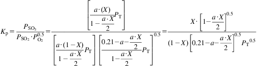
Table 7E5.2 shows the conversion for different pressures and temperatures for a=0.06. Fig. 7E5.1 shows the results repeating the procedure for the rest.
Table 7E5.2
Conversion as a Function of Pressure and Temperature
| P=0.8 atm | P=1 atm | P=1.5 atm | ||
| Kp (T) | T | X | X | X |
| 3819.442708 | 600 | 0.99916852 | 0.99925623 | 0.99939263 |
| 884.3320899 | 650 | 0.9964198 | 0.99679643 | 0.99738259 |
| 252.3480772 | 700 | 0.98757686 | 0.98887226 | 0.99089366 |
| 85.11380382 | 750 | 0.96413344 | 0.96778569 | 0.97352465 |
| 32.88516309 | 800 | 0.91261604 | 0.92104806 | 0.93449999 |
| 14.20980883 | 850 | 0.82004997 | 0.83570639 | 0.86136331 |
| 6.740105069 | 900 | 0.68664695 | 0.7096612 | 0.74884936 |
| 1.896705921 | 1000 | 0.38827411 | 0.41448564 | 0.46323565 |
