
Biomass
Abstract
Biomass is a natural carbonous resource. It is used to produce syngas (already evaluated in chapter: Syngas). Lately however, new bioprocesses have been developed to produce a number of biofuels and power in an attempt to reduce our dependence on fossil resources. In this chapter the processes that transform biomass into sugars and oil via biochemical pathways are analyzed. The main examples, such as the production of biodiesel and bioethanol, are shown. The performance of the biomass pretreatments, chemical reactions, and final product purifications are analyzed based on mass and energy balances, reaction engineering principles with examples in MATLAB, and unit operation approaches for product purification, including the typical water–ethanol distillation tower. Shortcut methods as well as exercises that use process simulators are proposed. Finally, biomass/biogas-based power cycles are described.
Keywords
Biomass; algae; bioethanol; biodiesel; fermentation; beer column; power
8.1 Biomass Types and Preprocessing
In this chapter we focus on the processing of different types of biomass for the production of chemicals, fuels, and power; paper and penicillin will also be described. It is interesting to note that by stopping the treatment process at an early stage, we can produce natural polymers such as cellulose, hemicellulose, lignin, and rubber. We also evaluate the production of synthetic rubber, an attempt to match the properties of a natural polymer. We start by describing the chemical composition of several common raw materials.
8.1.1 Grain
Grain is a source of carbohydrates—the raw material for first-generation bioethanol—as well as protein and fat. Wheat and corn grain are made of starch, a natural polymer that consists of glucose molecules, as seen in Fig. 8.1.

The pretreatment of the grain consists of breaking bonds to obtain sugar monomers of glucose. The process consists of liquefaction, and takes place at 90°C and a pH from 6 to 6.5 for 30 min. The starch is broken into maltose. In a second step, the maltose is further hydrolyzed at 65°C and pH 5.5 for 30 min (ie, saccharification) to obtain glucose. These are the reactions:
8.1.2 Lignocellulosic Biomass
Although grain is an interesting source of sugars, its use for biofuel production poses an ethical dilemma because it competes with the food supply chain. Thus, second-generation biofuels are based on the use of biomass that does not compete with the food chain, either in terms of final use of the product or acreage. Lignocellulosic raw materials consist of cellulose, hemicellulose, and lignin. Lignin provides structure to the plant, hemicelluose is responsible for internal structure, and cellulose is the internal polymer. Lignin is a polymer of aromatic monomers, while hemicellulose and cellulose are made of sugar monomers. Fig. 8.2 shows the structure of a plant and the chemical composition of the main components of the plant wall. A number of uses for lignocellulosic raw materials are highlighted: biooil, syngas, sugar, and paper production.

8.1.2.1 Biooil production
This is a thermochemical path used to partially break the biomass into medium-size chemicals. It operates at medium temperatures, and the composition of the products depends on the rate of the process. The faster the process, the higher the liquid content (see Fig. 8.3). Gas and char are also produced. Thus, fast pyrolysis is recommended for chemicals and fuels production. The main drawback of the process is the wide range of products generated and their high corrosivity. An upgrade to the process is therefore required for proper further use of the biooil. Hydrocracking and catalytic cracking are two methods for upgrading (see Chapter 5: Syngas).

8.1.2.2 Syngas production
Syngas production from biomass is similar to that from any other carbonous substrates. It consists of the partial oxidation of biomass at high temperature (1000°C) to produce a gas phase. The difference lies in the composition of the gas. In addition to carbon monoxide (CO), carbon dioxide (CO2), hydrogen (H2), hydrocarbons, tar, and char, we also find hydrogen sulfide (H2S) and ammonia (NH3). Thus, raw syngas follows the gas cleaning process. Therefore, we refer the reader to Chapter 5, Syngas for further descriptions of the gasification and gas purification steps.
8.1.2.3 Sugar production
Sugar production from lignocellulosic biomass uses moderate pretreatment processes (below 200°C) to break plant structures down only as far as their monomers. The pretreatments can be classified into physicochemical, chemical, and enzymatic. The aim is to expose the sugar-containing polymers, namely cellulose and hemicellulose; this makes them more accessible for hydrolysis to sugars. Fig. 8.4 shows the desired effect of pretreatment: breakage of the physical structure into pieces.

8.1.2.3.1 Physicochemical processes
These processes are based on the use of CO2, steam, or NH3 under pressure; when the pressure is released, the biomass structure is broken. Among the different processes available, ammonia fiber explosion (AFEX) is one of the few that has reached the industrial development stage. The AFEX process puts biomass into contact with an NH3 solution (20 atm, 90–180°C) so that when expanded, the biomass structure breaks into pieces. The method does not produce byproducts, and shows high yield. For years the disadvantage was the energy required to recover the NH3—until recent developments by Prof. Dale’s group at Michigan State University. Fig. 8.5 shows the flowsheet (Martín and Grossmann, 2012a). After the reactor pretreatment, the pressure is released and part of the NH3 is recovered. The slurry is distilled to recover the rest of the NH3. Traces of NH3 remain in the slurry, but they can be used as nutrients in further fermentation stages. Based on the experimental data from Garlock et al. (2012), a correlation that depends on the NH3-to-biomass ratio, the operating temperature, the water-to-biomass ratio, and the residence time is presented; this can be used to compute the yield. The range of the operating variables is shown in Table 8.1.
(8.1)

8.1.2.3.2 Chemical pretreatment
Chemical pretreatment entails the use of alkali or acid solutions, peroxides, or even ozone to break down plant structure. The National Energy Renewable Lab (NREL) has developed a dilute sulfuric acid pretreatment (Aden and Foust, 2009) in which a solution of 0.5–2% H2SO4 is put into contact with biomass at 140–180°C and 12 atm for up to 1.5 h. In the expansion, part of the water is recovered and recycled, while the slurry is separated so that the liquid phase is neutralized with CaO, producing gypsum. After filtering the gypsum, both streams are mixed again for further processing. Fig. 8.6 shows the flowsheet for the process.

Based on experimental data, Martín and Grossmann (2014) developed models for the yield to cellulose and hemicellulose as a function of the operation temperature, the acid concentration, the residence time, and the enzyme added in the hydrolysis part, see eqs. (8.2) and (8.3). Table 8.2 shows the range for the operating variables.
(8.2)
 (8.2)
(8.2)
(8.3)
 (8.3)
(8.3)
8.1.2.3.3 Enzymatic pretreatment
These are slow processes and are not yet competitive.
Once the physical structure of the biomass is broken and the polymers, cellulose, and hemicellulose exposed, the next stage is enzymatic hydrolysis, which produces sugars. The hydrolysis is typically an endothermic set of reactions that takes place at 50°C:
Alternatively, these polymers can be used for the production of paper.
8.1.2.4 Paper production
Paper production consists of six stages. (1) The biomass is ground into chips. (2) The chips are cooked with alkali solutions from 75–80°C to 130–170°C to solubilize the lignin and release the cellulosic polymers. (3) The material is then washed to remove the lignin. (4) Oxygenation is performed in order to minimize the quantity of chemicals required in the bleaching step. (5) The material is bleached to provide a white color. This is the most contaminating stage due to the chemicals necessary to process the raw materials (Cl2 in particular). Both total chlorine-free and elementary chlorine-free processes are available. (6) Sheets are produced.
8.1.3 Seeds
First-generation biodiesel processes use high oil content seeds as raw materials. The oil is extracted using crushers. The process consists of a number of stages. The seeds are heated and milled, and then the flakes are slightly heated to improve the oil extraction. The cake obtained can be further processed using solvents or by means of cold pressing using a screw. Sometimes both methods are combined to increase the yield. The oil must later be purified. Flash distillation, filtration, or sedimentation can be used for the oil refining step. The biodiesel yields of different seeds are shown in Table 8.3. Fig. 8.7 shows the process.
Table 8.3
Yield of Biodiesel From Different Seeds (http://www.bioenergy.wa.gov/oilseed.aspx)
| Plant | Yield (Seed) (lbs./acre) | Biodiesel (Gal./acre) |
| Safflower | 1500 | 83 |
| Rice | 6600 | 88 |
| Sunflower | 1200 | 100 |
| Peanut | 2800 | 113 |
| Rapeseed | 2000 | 127 |
| Coconut | 3600 | 287 |
| Oil palm | 6251 | 635 |

8.1.4 Algae
Algae are another alternative for the production of biofuels. Due to their high yield to biomass—typically an order of magnitude or two higher than other seeds per area—algae promise higher production. Algae grow by capturing CO2 (although other carbonous sources can be used), and use sunlight as an energy source. Algae store lipids (up to 70%), starch (up to 50%), protein, and other components. The basic stoichiometry of the algae growing process is as follows:
Algae are grown in ponds or photobioreactors. Ponds are the cheaper option, and only civil engineering work is required to create an operational system. Water flows through 20 cm-deep channels into which CO2 and nutrients are injected. However, ponds present several drawbacks: they are easily contaminated and process control is difficult. Photobioreactors, on the other hand, offer a controlled environment. However, solar exposure is difficult and the investment cost is high. Fig. 8.8 shows examples of both systems.

The algae growth rate is a function of the solar energy:
(8.4)
where I0 (kWh/m2/d) is the solar intensity, ηmax is the utilization of the light by the algae (0.045; Walker, 2009), and the algae heating value is 21 kJ/g (Park et al., 2011). Growth rate values of 50 g/m2 d are optimistic but feasible. Carbon dioxide consumption is related to algae growth as shown in the following equation:
(8.5)
In addition to CO2, NH3 (or nitrates) up to 0.8% and phosphates up to 0.6% (both with respect to dry biomass) are needed. Evaporation accounts for water loss of 6.2 m3/day (Sazdanoff, 2006).
Once the algae are produced, the limiting stage for oil production in terms of cost is the harvesting. This step typically consists of flotation followed by centrifugation or filtration and biomass drying to reach moistures below 10%. Alternatively, there is a capillarity-based process that has been proposed by Univenture; it is supposed to yield a biomass cake with 5% moisture and also consume less energy. The dry biomass is processed and oil extracted, as in the seed-based case. The remaining biomass cake consists mainly of starch and protein. The starch can be used to produce ethanol, similar to first-generation techniques for bioethanol production from corn or wheat (Martín and Grossmann, 2013b).
8.1.5 Natural Rubber
8.1.5.1 Historical perspective
Rubber is native to South America, and was already being used by the natives prior to the arrival of the Spanish in 1492. In 1511 the Spanish realized how useful this material with elastic and waterproof properties could be.
Rubber, also called “India rubber” or caoutchouc, is a polymer of isoprene. It is harvested from trees in the form of latex, an aqueous dispersion of polyisoprene particles stabilized in proteinaceous surfactants. The major commercial source of natural latex is the Pará rubber tree (Hevea brasiliensis), which is harvested regularly to obtain it. Latex hardens soon after extraction. This fact motivated research into how to dissolve latex.
In 1770 Joseph Priestley realized that rubber could erase pencil marks. Later, in 1791, the first commercial application to waterproof surfaces was presented. The vulcanization of natural rubber (which cross-links the polymer with sulfur) dates back to Charles Goodyear’s work in 1839. This represents the beginning of the use of rubber for manufacturing tires. The lack of supply of natural rubber during WWII led to the development of synthetic polymers to match the natural one. The main producers of natural rubber are Malaysia, India, Indonesia, Thailand, and Sri Lanka, with annual production over 4 million tons.
8.1.5.2 Polymerization processes
Synthetic rubber (cis-1,4-polyisoprene) can be obtained via radical chain polymerization of the monomer (isoprene). It was the isolation of this chemical during the pyrolysis of natural rubber that provided the key to identifying the building block. The evolution of the catalysts occurs for 70 years when Ziegler-type catalyst was used (1955). There are four main types of polymerization: (1) block or bulk polymerization, (2) polymerization in solution, (3) bead or pearl polymerization, and (4) emulsion polymerization.
Bulk polymerization occurs in molds with the own monomer and initiators. It produces high purity polymers with high molecular weight. Polymerization in solution requires the use of solvents. It can be homogeneous or heterogeneous. Bead polymerization is carried out in water by dispersion of the insoluble monomer to produce small droplets of controlled size. This polymerization technique is similar to bulk polymerization, but is performed in microreactors, which allow easier heat removal. It does, however, require the use of colloids to avoid droplet coalescence. Finally, emulsion polymerization is carried out by adding the water-insoluble monomer to an aqueous solution of an emulsifier. The product is a water emulsion of polymer particles. Emulsion polymerization is used for synthetic rubber production.
Mechanism and kinetics
Radical polymerization is based on double bond opening and free radical chain growth, as per the reaction below:

It requires the use of initiators (I), Ziegler–Natta catalysts. The proposed reaction mechanism consists of three main steps (initiation, propagation, and termination) and is believed to proceed as follows (Odian, 2004):
| Initialization: | |
| Propagation: | |
| Propagation: | |
| Termination by combination | |
| Termination by disproportion | |
| Transfer to monomer |
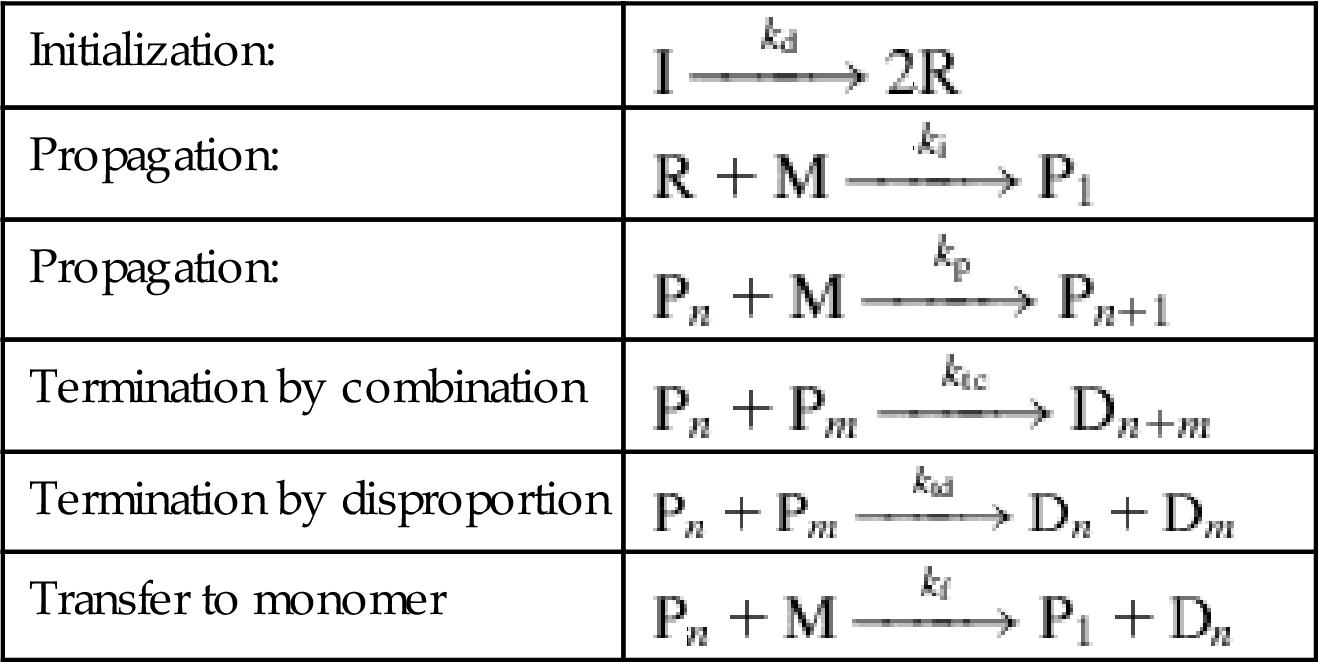
The kinetics proceed as follows:
(8.6)
where f is the initiator efficiency. Assuming a steady-state for the rates and adding together all of the monomer kinetics, we have:
(8.7)
(8.8)
The polymerization lasts 15 h at 50°C in a stirred tank. The conversion yield is 75%. The molecular weight of the product is computed using statistical moments. A complete model for a polymerization reactor can be found in Martín (2014). After the reactor step, a stripper is used to recover hydrocarbons. Finally, the rubber crumb slurry is dewatered and dried in an extruder. The dry crumbs are ready for shipment.
8.2 Intermediate Processing
8.2.1 Sugars
This section covers the production of a number of chemicals, mainly for the biofuels industry. We also cover the production of antibiotics such as penicillin via fermentation.
8.2.1.1 Bioethanol
Bioethanol can be produced via sugar fermentation. Saccharomyces cerevisiae is capable of anaerobically fermenting glucose at 32–38°C to produce a solution of up to 15% by weight of ethanol. Overpressure is typically used to prevent the entrance of air into the system. Fermentation of pentoses is more complex. Zymomonas mobilis has been identified as appropriate for fermenting pentoses and hexoses simultaneously. In addition to ethanol, byproducts such as glycerol, succinic acid, acetic acid, and lactic acid are also produced. Table 8.4 shows the various reactions and the typical conversions in second-generation bioethanol processes (Aden and Foust, 2009). See Fig. 2.6 for a block diagram of the process.
Table 8.4
Reactions and Conversions in Second-Generation Bioethanol Production
| Reaction | Conversion |
| Glucose→2 Ethanol+2CO2 | Glucose 0.92 |
| Glucose+1.2NH3→6 Z. mobilis+2.4H2O+0.3O2 | Glucose 0.04 |
| Glucose+2H2O→Glycerol+O2 | Glucose 0.002 |
| Glucose+2CO2→2 Succinic acid+O2 | Glucose 0.008 |
| Glucose→3 Acetic acid | Glucose 0.022 |
| Glucose→2 Lactic acid | Glucose 0.013 |
| 3 Xylose → 5 Ethanol+5CO2 | Xylose 0.8 |
| Xylose+NH3→5 Z. mobilis+2H2O+0.25O2 | Xylose 0.03 |
| 3 Xylose+5H2O→5 Glycerol+2.5O2 | Xylose 0.02 |
| 3 Xylose+5 CO2→5 Succinic acid+2.5O2 | Xylose 0.03 |
| 2 Xylose→5 Acetic acid | Xylose 0.01 |
| 3 Xylose→5 Lactic acid | Xylose 0.01 |
The reactions that yield ethanol are exothermic:
The reaction time is about 24 h at 0.12 MPa, which helps prevent the entrance of air into the system. The maximum concentration of ethanol in the water is 6–8%.
Example 8.1
Model the fermentor for second-generation bioethanol production based on Krishnan et al. (1999).
Solution
The kinetic model for ethanol production via fermentation is based on the Michaelis–Menten mechanism:
In the case of ethanol production, there is both substrate and product inhibition:
Assuming a steady-state for [E], [EI], and finally [ES], the modified Monod kinetics are given as follows:
Next, the product inhibition is included:
The kinetics models for the different species involved are given in the equations that follow, where G represents glucose and X represents xylose. The parameters for the fermentation are given in Table 8E1.1 (Krishnan et al., 1999).


Table 8E1.1
Kinetic Parameters for Fermentation
| Parameter | Glucose Fermentation | Xylose Fermentation |
| μm (h−1) | 0.662 | 0.190 |
| νm (h−1) | 2.005 | 0.250 |
| Ks (g/L) | 0.565 | 3.400 |
| Ks′ (g/L) | 1.342 | 3.400 |
| Ki (g/L) | 283.700 | 18.100 |
| Ki′ (g/L) | 4890.000 | 81.300 |
| Pm (g/L) | 95.4 for P≤95.4 g/L | |
| 129.9 for 95.4≤P≤129 g/L | 59.040 | |
| Pm′ (g/L) | 103 for P≤103 g/L | |
| 136.4 for 103≤P≤136.4 g/L | 60.200 | |
| β | 1.29 for P≤95.4 g/L | |
| 0.25 for 95.4≤P≤129 g/L | 1.036 | |
| γ | 1.42 for P≤95.4 g/L | 0.608 |
| m (h−1) | 0.097 | 0.067 |
| YP/S (g/g) | 0.470 | 0.400 |
| YX/S (g/g) | 0.115 | 0.162 |
The model for solving the equations can be written in any software. The following is example code for MATLAB:
[a,b]=ode15s('Fermen',[0 36],[200,50,0,1]);
plot(a,b(:,1),'k',a,b(:,2),'k--',a,b(:,3),'ko',a,b(:,4),'k.')
xlabel('t(h)')
ylabel('g/L')
legend('Glucose','Xylose','Ethanol','Cells')
function Reactor=Fermen(t,x)
Glucose=x(1);
xylose=x(2);
ethanol=x(3);
cells=x(4);
v_m_g=2.005;
v_m_x=0.250;
K_s_g=0.565;
K_i_g=283.7;
K_s_x=3.4;
K_i_x=18.1;
K_sp_g=1.341;
K_ip_g=4890;
K_sp_x=3.4;
K_ip_x=81.3;
m_g=0.097;
m_x=0.067;
Y_P_S_g=0.470;
Y_P_S_x=0.4;
P_m_x=59.04;
P_mp_x=60.2;
Beta_x=1.036;
gamma_x=0.608;
if ethanol <95.4;
P_m_g=95.4;
Beta_g=1.29;
gamma_g=1.42;
else
P_m_g=129;
Beta_g=0.25;
gamma_g=0;
end
if ethanol <103;
P_mp_g=103;
else
P_mp_g=136;
end
if cells < 5;
mu_m_g=0.152*(cells)^(-0.461);
v_m_g=1.887*(cells)^(-0.434);
mu_m_x=0.075*(cells)^(-0.438);
v_m_x=0.16*(cells)^(-0.233);
else
mu_m_g =0.662;
v_m_g= 2.005;
mu_m_x=0.190;
v_m_x= 0.25;
end
mu_g=mu_m_g*Glucose*(1-(ethanol/P_m_g)^Beta_g)/(K_s_g+Glucose+Glucose^2/K_i_g);
mu_x=mu_m_x*xylose*(1-(ethanol/P_m_x)^Beta_x)/(K_s_x+xylose+xylose^2/K_i_x);
v_g=v_m_g*Glucose*(1-(ethanol/P_mp_g)^gamma_g)/(K_sp_g+Glucose+Glucose^2/K_ip_g);
v_x=v_m_x*xylose*(1-(ethanol/P_mp_x)^gamma_x)/(K_sp_x+Glucose+Glucose^2/K_ip_x);
Reactor(1,1)=-(1/Y_P_S_g)*v_g*cells;
Reactor(2,1)=-(1/Y_P_S_x)*v_x*cells;
Reactor(3,1)=(v_g+v_x)*cells;
Reactor(4,1)=cells*((Glucose)*mu_g/(Glucose+xylose)+(xylose)*mu_x/(Glucose+xylose));
The profile of the species over time can be seen in (Fig. 8E1.1)

8.2.1.2 Biodiesel
Glucose and xylose have recently been fermented into biodiesel (fatty acid ethyl esters, FAEE). The fermentation takes place aerobically at 32–38°C, with a yield of 0.35 g/g sugar. The concentration of FAEE in the reactor is fixed at 0.01 kg/kg. Biodiesel is immiscible in water, and therefore the separation of the organic and aqueous phases is easy. However, ethanol and glycerol are also produced, and remain in the aqueous phase. This reduces the yield of carbon to FAEE. Table 8.5 shows some typical conversions (Martín and Grossmann, 2015).
Table 8.5
Conversions of Sugars into FAEE and Byproducts
| Reaction | Conversion | DHr (kJ/mol) |
| 9 Glucose+2O2→2C18H36O2+18CO2+18H2O | Glucose 0.3 | −405 |
| Glucose→2 Ethanol+2CO2 | Glucose 0.3 | −84,394 |
| Glucose+1.2NH3→6 Z. mobilis+2.4H2O+0.3O2 | Glucose 0.1 | NA |
| Glucose+2H2O→2 Glycerol+O2 | Glucose 0.3 | 504 |
| 27 Xylose+5O2→5C18H36O2+45CO2+45H2O | Xylose 0.2 | −338 |
| 3 Xylose→5 Ethanol+5CO2 | Xylose 0.2 | −74,986 |
| Xylose+NH3→5 Z. mobilis+2H2O+0.25O2 | Xylose 0.2 | NA |
| 3 Xylose+5H2O→5 Glycerol+2.5O2 | Xylose 0.2 | 418 |
8.2.1.3 Ibutene
Sugars can also be a source of valuable chemicals. Ibutene, a C4 chemical, can be produced from glucose fermentation. The advantage of this process is that the product is in the gas phase and thus no energy-intensive dehydration is required. Ibutene must be separated from the CO2 (Martín and Grossmann, 2014).
8.2.1.4 Furans
Dehydration of C6 sugars yields hydroxymethyl furfural, an intermediate in the production of dimethyl furfural (DMF). C5 sugars can produce furfural as presented in the chemical reactions below:


8.2.1.5 Butanol
Sugars can also be fermented to produce butanol. The typical reaction is the so-called ABE fermentation in which, apart from butanol, both ethanol and acetone are produced. The maximum concentration of butanol is obtained after 48 h of fermentation (Papoutsakis, 1984). The reaction looks like this:
8.2.1.6 Penicillin
Penicillin was discovered in 1928 when Alexander Fleming, a biologist, realized that one of his experimental setups was contaminated but did not grow any bacteria. He tracked down the culprit—penicillin—and thus the first natural antibiotic was found. The first purification of penicillin is credited to Howard Florey and Ernst Chain by 1939. There are currently around 50 drugs that are classified as penicillins.
Sugars such as glucose are used as substrates to produce penicillin via aerobic fermentation. Oxygen is fed to a stirred tank. The resulting reaction is exothermic and requires constant cooling. The pH, dissolved oxygen, and temperature of the reaction are tightly controlled. It is a fed-batch operation where the substrate is added in small increments. This change in volume must be included in the analysis. Due to the viscosity of the medium and mass transfer limitations, bubble column reactors are also used. The process for the production of the penicillin is modeled on Monod kinetics, as presented in Eq. (8.9). Further details of the model can be found in Birol et al. (2002). The reactor operates at 20–24°C and pH 6.5. After 40 h, penicillin is secreted, and growth stops after about 7 days.
(8.9)
 (8.9)
(8.9)
The reaction generates energy, and only if this energy is properly removed can the reaction be considered isothermal. The mass transfer between the gas and liquid phases depends on the hydrodynamics and properties of the system. The term kLa refers to the liquid film resistance, kL, and the contact area, a, between the phases. The two-film theory considers the resistance in both the stagnant liquid film and the gas–liquid film at interphase:
(8.10)
It has been experimentally proven that in gas–liquid processes the main resistance is usually the resistance of the liquid phase (kL).
Although kL and a can be determined separately, the area corresponds to that provided by the bubble dispersion in the tank, and can be estimated using either Eqs. (8.11–8.12) as per Gogate et al. (2000):
(8.11)
(8.12)
or Eq. (8.13) from Calderbank (1958):
(8.13)
kL is a function of the diffusivity of the gas to the liquid and the gas-liquid contact time (Higbie, 1935). The complexity of evaluating these two variables (kL and a) separately has led to the tradition of using the empirical prediction of kLa:
(8.14)
where uG is the superficial gas velocity in the cross sectional area of the tank and Pg is the aeration power as a function of the gas flow rate, Qc, the impeller diameter, T, and the liquid volume, V, the stirrer angular velocity, N, and the power in absence of aeration, P, as given by Eq. (8.15):
(8.15)
Biological media are characterized by high viscosities that affect the diffusion of gas into the liquid phase. Thus, Eq. (8.14) is corrected by the viscosity as follows:
(8.16)
Furthermore, in the presence of solids, as in the case of the Penicillium, Eq. (8.14) can also be corrected by the fraction of solids, X, as follows:
(8.17)
with k=33.59, α=−0.0463, β=0.94, and γ=−1.012 (Kielbus-Rapala and Karcz, 2011).
8.2.2 Syngas
Syngas is a versatile raw material (see Chapter 5: Syngas). No further discussion regarding its production, composition adjustment, or cleanup is offered here, only its use within the biofuels industry (Martín and Grossmann, 2013a).
Syngas fermentation is one way to produce ethanol. Syngas with an H2-to-CO ratio equal to 1 and can be fermented anaerobically at 32–38°C. The reaction conversion is around 70%, but ethanol inhibits the process and thus its concentration in water cannot typically exceed 5%.
Syngas can also be used to produce ethanol and other fuels via catalytic synthesis.
Ethanol production requires an H2-to-CO ratio of 1 for a global conversion of 60%. The process, known as mixed alcohol synthesis, is based on the hydrogenation of CO over a catalyst, similar to Fischer–Tropsch (FT) processes. The reaction is carried out at 68 bar and 300°C to obtain a range of alcohols of small molecular weight, including methanol, ethanol, propanol, and also butanol and pentanol in smaller amounts. The reactions with their conversions are as follows:
![]()
![]()
![]()
![]()
![]()
![]()
![]()
![]()
Methanol, H2, and FT fuel production from syngas is detailed in Chapter 5, Syngas.
8.2.3 Oil
Oil obtained from various sources can be transformed into biodiesel via transesterification. The reasons for not using oil itself as fuel are its higher viscosity and its differences from current diesel specifications (which do not allow its proper combustion in engines). Apart from transesterfication, hydrotreating emulsions can also be used to break oil into smaller pieces that can be used in diesel engines. This section focuses on transesterification:
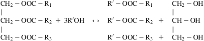
Although different short-chain alcohols can be used, methanol’s low cost and fast reaction kinetics have made it the alcohol of choice for transesterification. Therefore, biodiesel is also known as fatty acid methyl esters (FAME). The low price of FAME is due to its fossil source, and therefore the word “biodiesel” loses its meaning. Lately, ethanol has been investigated as an alternative to methanol. It is currently produced in biorefineries and its products are called fatty acid ethyl esters (FAEE).
The transesterification reaction is governed by an equilibrium that can be driven to products by controlling the alcohol-to-oil ratio, the operating pressure (supercritical conditions only) and temperature, the catalyst load, and the residence time. Common catalysts are alkalis and acids, but these suffer from a series of disadvantages. Alkali catalysts, in spite of high conversion, are sensitive to the presence of water and free fatty acids (FFA); therefore, a pretreatment with an acid catalyst is necessary. The yield of this pretreatment using a solid acid catalyst can be computed using Eq. (8.18) (Martín and Grossmann, 2012b) as a function of the methanol-to-FFA ratio, the operating temperature, and the residence time:
(8.18)
Once treated, the oil is transformed into FAME using KOH or NaOH as a catalyst. The use of KOH has the advantage that it can later be easily separated from the liquid mixture by precipitation using H3PO4 because K3PO4 is only slightly soluble in water. Before the neutralization step, the biodiesel must be washed, which increases the water consumption of the facility. A model to predict the yield of the transesterification process as a function of the methanol-to-oil ratio, the temperature of operation, and the catalyst load (Martín and Grossmann, 2012b) is given by Eq. (8.19). Table 8.6 shows the typical range of the operating variables.
(8.19)
Table 8.6
Range of Operation of the Variables (Alkali)
| Variable | Lower Bound | Upper Bound |
| Temperature (°C) | 45 | 65 |
| Ratio of methanol (mol/mol) | 4.5 | 7.5 |
| Cat (%) | 0.5 | 1.5 |
Homogeneous acid catalysts such as H2SO4 have the advantage of not being sensitive to the presence of FFAs; however, the reaction kinetics are slow. Furthermore, as in the case of KOH or NaOH, a washing step is required before neutralization. Sulfuric acid can be neutralized using CaO. The reaction between CaO and sulfuric acid produces CaSO4 (gypsum), which precipitates and can be easily separated.
In addition to homogeneous catalysis, heterogeneous methods are also being studied as a way to simplify the biodiesel separation stages. The catalyst can easily be recovered after the reaction. A model to compute the yield of heterogeneous catalyst using methanol as the alcohol can be seen in Eq. (8.20) as a function of the methanol-to-oil ratio, the temperature of operation, and the catalyst load (Martín and Grossmann, 2012b). Table 8.7 shows the range of the operating variables for this case.
(8.20)
Table 8.7
Range of Operation of the Variables (Heterogeneous Catalysis)
| Variable | Lower Bound | Upper Bound |
| Temperature (°C) | 40 | 60 |
| Ratio of methanol (mol/mol) | 6 | 12 |
| Cat (%) | 1 | 4 |
The use of supported enzymes and a noncatalyzed reaction under supercritical conditions are other alternatives that have been proposed, but the economics are not as good. Models for the yield of heterogeneous catalysts can also be found in Martín and Grossmann, 2012b.
As mentioned above, ethanol can also be used. Severson et al. (2013) developed several models to predict the yield of the reaction as a function of the ethanol-to-oil molar ratio, the operating temperature, the catalyst load, and the residence time. The two most promising processes used either KOH or enzymes as catalysts. The models are presented below, and Tables 8.8 and 8.9 show the range of the operating variables.
Table 8.8
Range of Operation of the Variables (Alkali Pretreatment)
| Variable | Lower Bound | Upper Bound |
| Temperature (°C) | 25 | 80 |
| Ratio of ethanol (mol/mol) | 3 | 20 |
| Catalyst (%) | 0.5 | 1.5 |
Table 8.9
Range of Operation of the Variables (Enzymatic Transesterification)
| Variable | Lower Bound | Upper Bound |
| Temperature (°C) | 20 | 45 |
| Ratio of ethanol (mol/mol) | 3 | 12 |
| Catalyst (%w/w) | 5 | 16 |
| Added water (%w/w) | 0 | 20 |
| Time (h) | 6 | 13 |
Using ethanol (KOH) we have the following:
(8.21)
Using ethanol (enzymatic) we have the following:
(8.22)
 (8.22)
Kinetics: The use of surface of response analysis for evaluating the yield of the transesterification equilibrium is an efficient way to evaluate a process that depends on a number of input variables such as temperature, concentration of species, catalyst load, and time. However, a more detailed analysis based on the reaction mechanism provides better insight. The process to produce biodiesel is a set of three reactions in equilibrium. Let TG be triglycerides, DG diglycerides, MG monoglycerides, ME methyl ester, and GL glycerol:
(8.23)
 (8.23)
The reactor design based on the kinetics is as follows:
(8.24)
 (8.24)
The rate constants depend on the oil, the catalyst, and the alcohol. Table 8.10 (Issariyakul and Dalai, 2012) shows some KOH 1% values from the literature; for this example equilibrium is achieved from 10 min onwards.

8.2.4 Biogas
Biogas is a mixture of mainly methane (50–70%) and CO2 (20–40%), and is produced from the anaerobic digestion (AD) of biomass. The various sources discussed above can be used as raw materials for its production. Biogas is an interesting product that provides further value to wastes, and also showcases a treatment technology (AD) for waste disposal. Apart from the use of biomass, biogas is typically produced from sludge and animal manure (either in slurry form or as a solid). Not only is biogas produced, but also digestate, an interesting fertilizer. The value of this fertilizer can be computed using the NPK index, representing the amount of nitrogen, phosphorous, and potassium.
8.2.4.1 Process description
The production of biogas takes place in a series of steps: hydrolysis, acidogenesis, acetogenesis, and methanogenesis. The first step, hydrolysis, breaks the biomass into smaller blocks for transformation into sugars, fatty acids, and amino acids. Several promising attempts have been made to use pretreatment methods (discussed in the lignocellulosic section) to improve yields. In acidogenesis (the second step), H2, CO2, acetate, and volatile fatty acids (VFA) and alcohols are produced. In the third step (acetogenesis), H2 and acetic acid are produced from VFA and alcohols. Finally, methanogenesis transforms the mixture of CO2 and H2 into methane. This final step runs in parallel to the acetogenesis step.
The operating conditions are classified by the residence time and the temperature. Psychrophilic conditions are those requiring low temperatures (<20°C) and long retention times (70–80 days). Mesophilic conditions reduce the retention time to 30 to 40 days, but double the operating temperature to 30–42°C. Finally, thermophilic conditions require 43–55°C, but only 15–20 days of retention time. Therefore, the digester is typically a large, closed tank; the gas is sent to a storage tank from there. Apart from continuous stirred tank reactors (CSTRs, often in series), plug flow reactors have also been applied to improve the performance of biogas plants (Bensmann et al., 2013).
The gas produced must be cleansed from NH3 or H2S before use as an energy source. Chapter 5, Syngas discusses a number of technologies.
8.2.4.2 Process analysis
8.2.4.2.1 Kinetics
The simplest process analysis is to consider a first-order rate model for the substrate utilization:
(8.25)
Contois in 1959 proposed a modified form of the Monod model for the first stages, and a Haldane function for the methanogenesis step (Mairet et al., 2012). pH and the gas–liquid mass transfer step must also be controlled.
(8.26)
 (8.26)
Complete models can be found elsewhere. The anaerobic digestion model (ADM-1; Batstone et al., 2002) is the basis for most analyses.
8.2.4.2.2 Gas composition
The actual composition of the gas depends not only on the operating conditions, but also on the composition of the feedstock. Apart from first principle analysis based on mass and energy balances, the biochemical reaction used for a basic analysis can be considered as follows:
(8.27)
If nitrogen from amino acids and protein is also considered, the equation becomes:
(8.28)
There are some statistical studies that provide the yield of gas as a function of the time, C-to-N ratio, and loading concentration (kg VS/m3), all of which are highly dependent on the biomass used as feedstock.
(8.29)
8.3 Product Purification
8.3.1 Ethanol Dehydation
Ethanol production via fermentation yields a diluted water–ethanol mixture, from 5–15% depending on the raw material. The separation is carried out by removing solids first and using a distillation column known as a beer column. Next, rectification and/or molecular sieves are used to produce anhydrous ethanol, which is ready for use as a fuel. Alternatively, extractive distillation has also been suggested.
A beer column allows recovery of most of the ethanol. However, the operation is energy-intensive. Therefore, the use of multieffect columns has been suggested so that the energy consumption can be cut by one-third and the cooling needs approximately by half. The operation of such columns was discussed in Chapter 2, Chemical processes. Fig. 8.9 shows the scheme of the operation.

Example 8.3
A single beer column operates with an L/D ratio of 1. The feed, 6 kg/s of a water–ethanol mixture, has 15% by weight of ethanol. The distillate has 80% purity by weight and the residue 2%. Compute the distillate and the residue, as well as the number of trays required for the column. Determine the energy removed and provided.
Solution
We assume that the flows are constant along the column. Thus the rectifying and stripping operating lines are as follows:
Because the data is by weight, we must convert it into molar ratios for each of the streams involved in the column operation. x is the mass fraction, F is the total mass flow rate, and M is the molar weight: ![]() (Table 8E3.1).
(Table 8E3.1).
Table 8E3.1
| x | y | |
| Feed | 0.15 | 0.0645933 |
| Distillate | 0.8 | 0.61016949 |
| Residue | 0.02 | 0.00792254 |
We formulate the mass balance as follows:
By solving the system we get D=1 kg/s and R=5 kg/s. Then, we use the McCabe method to compute the number of trays. Due to the nonideal behavior of the mixture, experimental data is used to plot the equilibrium curve. Next, using D, R, and the L/D ratio we plot the operating lines:
q line represents the intersection between the stripping and rectifying lines. Thus we have seven trays required for such separation (see Fig. 8E3.1). The energy involved in the condenser, Qw, and the reboiler, QH, are computed as follows:

Final dehydration: Fuel-quality ethanol is achieved only by surpassing the azeotrope (96% by weight). Therefore, a number of strategies have been suggested and evaluated, such as extractive distillation, pervaporation, and the use of molecular sieves. Among them, molecular sieves use silica gel or zeolites as adsorbent beds so that they retain the water. The operation of these units is similar to pressure swing adsorption (PSA) systems, except for the fact that there is no pressurization–expansion stage (see chapters Air and Syngas for an evaluation of adsorbent beds). Next, a stream of hot air is used to regenerate the beds. Pervaporation consists of the use of membranes permeable to one of the components so that by evaporation, ethanol is recovered. The use of molecular sieves is the technology of choice in most industrial facilities, and provides an advantage in terms of energy consumption.
Example 8.4
A second-generation bioethanol production facility processes biomass that contains cellulose (assume glucose for calculations), hemicellulose (xylose), and lignin. The conversion from glucose to ethanol is 90%, and that from xylose is 80%. Ninety-six percent (96%) of the ethanol produced is recovered. If the fractions of cellulose and hemicellulose in the feedstock are the same, the consumption of energy is 7000 kJ/kg of ethanol produced, and it is possible to obtain up to 19,500 kJ/kg of lignin. Compute the minimum amount of lignin a certain biomass needs to contain for the facility to be energy self-sufficient.
Solution
Assume 100 kg of initial biomass. We formulate the mass and energy balances for the plant composition, the ethanol production, and the energy required and produced as follows:

Solving this system of equations we get the results shown in Table 8E4.1:
Table 8E4.1
| Fermentation | ||||||
| Biomass | 100 | PM | Conv | Ethanol | Recovery | |
| Cellulose | 0.42196144 | 180 | 0.9 | 19.4102261 | 0.96 | 18.6338171 |
| Hemicellulose | 0.42196144 | 150 | 0.8 | 25.8803015 | 0.96 | 24.8450894 |
| Lignin | 0.15607813 | |||||
| Total | 1.000001 | |||||
| Energy (kJ/kg Lig) | 19500 | 304352.345 | ||||
| Consumption (kJ/kg et) | 7000 | 304352.345 | 0 | |||

8.3.2 Hydrocarbon and Alcohol Mixture Separation
FT processes and mixed alcohol synthesis require the use of distillation to separate the products. FT liquid fuels are separated using petrochemical-based technologies (see also chapters: Chemical processes and Syngas). In the case of mixed alcohols, a sequence of distillation columns is required; see Chapter 2, Chemical processes for the heuristics behind the technique, and Fig. 2.1 for a block flowsheet of the process. The separation of butanol mixtures is more complex due to the inmiscibility between water and ethanol. Recently a hybrid extraction–distillation scheme was proposed that uses mesitylene in an extraction column that processes the fermentation broth. This setup is followed by a sequence of three distillation columns operating at 1, 2, and 0.5 bar, respectively, to separate the solvent, mesitylene, butanol, acetone, and ethanol (Kramer et al., 2011). Ibutene purification is the simplest in the sense that it is a gas produced in the fermentation. Therefore, it exits the reactor together with CO2 and oxygen. PSA and membrane systems can be used for its purification.
8.3.3 Alcohol Recovery: Biodiesel
As presented in the analysis of the equilibrium towards biodiesel, an excess of alcohol is typically used to drive the reaction into biodiesel. However, the decision concerning the excess of alcohol can be made not just at the reactor level (aiming at higher conversions), but also at the process level. The reason is because for a larger excess of alcohols, the conversion increases, as well as the energy required to recover the excess. Therefore, there is a tradeoff to be solved (Martín and Grossmann, 2012b). Fig. 8.10 shows the flowsheet for the production of biodiesel using heterogeneous catalysts.

The distillation column or the flash separation to recover the alcohols must work in such a way that the temperature of operation is below 150°C to avoid glycerol decomposition. This column presents the particular feature that the feed and the bottom stream are phases. Thus, the vapor pressure is that given by both phases as follows:
(8.30)
Once the alcohol has been recovered, polar and nonpolar phases are separated at around 40–60°C for ethanol and methanol, respectively. In the case of a homogeneous catalyst, water is added in the separation to help remove the catalyst. The polar phase contains glycerol, alcohols and the homogeneous catalyst. The nonpolar phase contains biodiesel and unconverted oil. The polar phase is neutralized, if needed, and later distilled to purify the glycerol. In the case where acid homogeneous catalysts are used, CaO is recommended for neutralization (as presented above). In the case where KOH is used, H3PO4 is recommended. The nonpolar phase is also distilled to purify the biodiesel. The distillate should be below 250°C to avoid decomposition. As a result, this column and the alcohol recovery columns are meant to operate under vacuum. Furthermore, the column processes an immiscible mixture, and therefore it has to be taken into account in boiling and dew point computations.
Glycerol, the main byproduct, has become an interesting carbon source for the production of chemicals such as H2 or syngas via reforming, ethanol, via fermentation, glycerol ethers, together with ibutene, polyesters, etc.
Example 8.5
An algae-based biodiesel facility grows algae with 40% by weight oil (molecular weight 884 kg/kmol), 25% starch (assumed to be glucose), 10% protein, and the rest inert material. The aim is to produce ethanol from the starch and biodiesel from oil (assume a molecular weight of 310 kg/kmol). The conversion of the sugar fermentation is 90%, and the transesterification reaction has a conversion of 95%. Determine the amount of ethanol, biodiesel, and glycerol sold to the market if we use part of the ethanol produced as a transesterifying agent.
Solution
We perform the mass balances based on the stoichiometry of the reactions below:

Let ConvG be the conversion of glucose, ConvL the lipids conversion, B the total initial biomass, and Xi the fraction of component i in the biomass (S starch, L Lipids):

Solving the system we get the following results (Table 8E5.1):
Table 8E5.1
| Prod EtOH | Prod Biodiesel | Products | |||||||
| Biomass | 100 | PM | Conv | kmol | kg | kmol | kg | kg | |
| Starch | 0.40 | 40.00 | 180.00 | 0.22 | 0.00 | 0.00 | |||
| Oil | 0.25 | 25.00 | 884.00 | 0.03 | 0.00 | 0.00 | |||
| Protein | 0.10 | 0.00 | 0.00 | ||||||
| Others | 0.20 | 0.00 | 0.00 | ||||||
| FAEE | 310.00 | 0.08 | 26.30 | 26.30 | |||||
| EtOH | 46.00 | 0.40 | 18.40 | −0.08 | −3.90 | 14.50 | |||
| Glycerol | 92.00 | 0.03 | 2.60 | 2.60 | |||||

8.3.4 Penicillin Purification
The process for purification of penicillin obtained via fermentation is more complex than the previous ones mentioned. Biomass must be separated from the culture. Next, penicillin is extracted, and if a solvent is used, a recovery stage must be added to the process. Subsequently, the liquid phase containing the penicillin is recovered by centrifugation. A second extraction is followed by crystallization (either via cooling or drowning) to purify it. Finally, washing and drying allow powder production. It is typically stored as a potassium or sodium salt. See Chapter 4, Water for the operation of crystallizers.
8.4 Thermodynamic Cycles
Biomass-based syngas, biogas, or the biomass itself can be used to produce energy in power cycles such as the Rankine cycle and the Brayton cycle (Moran and Shapiro, 2000).
8.4.1 Rankine Cycle
The most widely used thermodynamic cycle is the regenerative Rankine cycle. High-pressure, superheated steam is obtained by burning the biomass. Alternatively, this energy can be obtained from burning any fossil fuel (as in thermal plants) or by using solar or geothermal energy. In the case of solar energy, concentrated solar power is required so that solar energy can reach an intensity capable of producing high-temperature steam. The variability in solar energy availability becomes a challenge for the operation of such a plant. Typically, a heat transfer fluid such as molten salts is used to buffer the absence of solar energy during the nighttime. However, in the long term, a different solution must be used. Hybrid plants, for example, which combine the use of different energy sources such as biomass and solar and allow continuous energy production over time (Vidal and Martín, 2015).
Once the steam is produced, it is fed to a steam turbine. The turbine is divided into three stages: high, medium, and low pressure. In the high-pressure turbine the steam expands into a moderated pressure. The steam is sent back to the boiler to be reheated. Next, the stream is expanded in the medium- and low-pressure turbines. Several extractions at different pressures are obtained from the turbines. These streams are used to reheat the condensed stream to close the cycle. A thermal plant scheme based on a Rankine cycle is presented in Fig. 8.11. The energy generated in the expansions is computed as an enthalpy difference. The temperature–entropy (TS) diagram of the cycle is shown in Fig. 8.11.
(8.31)

The enthalpy is a function of the temperature and the pressure. See Appendix B (Thermodynamic Data) to compute the enthalpy. The isentropic efficiency of the turbine (typically from 0.7–0.9) is computed using Eq. (8.32):
(8.32)
where the entropy of the stream is also a function of the pressure and temperature. For a detailed model of the cycle shown in Fig. 8.11, we refer the reader to the supplementary material in Vidal and Martín (2015).
8.4.2 Brayton Cycle
Compressed air is used to burn a fuel (ie, syngas) in a combustion chamber. When burned, the gas heats up to a high temperature that can be computed using Eq. (8.33):

(8.33)
Next, it is fed to a gas turbine. In the gas turbine the superheated gas is expanded isentropically to produce power. The energy involved in the compression of the air and that obtained in the expansion can be computed using Eq. (8.34), where k is around 1.4. The cycle diagrams can be seen in Fig. 8.12.
(8.34)

8.5 Problems
P8.1. In a facility for the production of biodiesel using methanol as the transesterifying agent, the conversion of the reaction can be estimated using the following equation:
Assuming that 96% of the methanol is recovered in the distillation column placed after the reactor (and recycling this amount), compute the methanol to be purchased and the methanol-to-oil ratio used if we aim for a conversion of 96% per pass.
P8.2. A single beer column with 11 trays is used to recover the ethanol from a dilute water–ethanol mixture. The feed, with a flowrate of 6 kg/s, enters as saturated liquid with a composition of 15% by weight of ethanol. The column operates with a reflux ratio L/D of 3. The residue is expected to have 2% by weight of ethanol. Determine the maximum concentration of ethanol in the distillate and the flowrates of residue and distillate.
P8.3. A second-generation bioethanol production facility processes biomass that contains cellulose (assume glucose for the calculations), hemicellulose (xylose), and lignin. The plant is supposed to operate self-sufficiently, but the energy consumption is 10% lower than the production. The uncertainty is in the conversion of xylose to glucose. The conversion from glucose to ethanol is 90%, and that from xylose should be 80%. Ninety-six percent (96%) of the ethanol produced is recovered. If the fraction of cellulose and hemicellulose in the feedstock is the same, the consumption of energy is 7000 kJ/kg of ethanol produced; it is possible to obtain up to 19,500 kJ/kg of lignin. Compute the actual conversion of xylose and the ethanol production of the facility per 100 kg of initial biomass.
P8.4. In the production of biodiesel from oil and methanol, the reactor conversion is given by this equation:
where the catalyst load is 1% of KaOH, Cat=1, and the reaction takes place at 60°C and 4 bar. The molar ratio between methanol and oil is 6. The products from the reactor are distilled and 98% of the unconverted methanol is recovered. Determine the methanol fed to the system per 100 kmol/h of oil, and the purge fraction if the commercial oil contains 0.02 kmol of water per kmol of oil. Water leaves with the methanol. The catalyst is capable of handling 5 kmol of water per 100 kmol of the methanol–oil mixture.
P8.5. An algae-based biodiesel facility grows algae containing oil (molecular weight 884 kg/kmol), starch (assume it is glucose), 10% protein, and 15% inert material. The aim is to produce ethanol from the starch and biodiesel from the oil (assume a molecular weight of 310 kg/kmol). The conversion of the sugar fermentation is 90% and the transesterification reaction has a conversion of 95%. The demand of ethanol and biodiesel is the same. Determine the composition required for the algae assuming that we internally use part of the ethanol produced for oil transesterification.
P8.6. Saccharomyces cerevisiae is used to ferment glucose to ethanol. Calculate the time it takes to obtain 80% conversion, assuming an initial concentration of cells of 0.1 g/L, an initial glucose concentration of 250 g/L, and the fact that the following rate laws hold:

Cp*=93 g/l; n=0.52; μmax=0.33 h−1; Ks=1.7; Yc/s=0.08 g/g; Yp/s=0.45 g/g (est)
Yp/c=0.56 g/g (est); kd=0.01 h−1; m=0.03 g substrate/(g cells h)
P8.7. A simple beer column processes a water–ethanol mixture (15% w/w ethanol). The distillate is 80% w/w ethanol and the residue is 98% water. The condenser consumes 20.19 kg/s of cooling water at 20°C, which exits at 30°C. The reboiler consumes 0.929 kg/s of steam (λ=1800 kJ/kg). Calculate the mass flow of distillate and residue, the L/D reflux ratio, and the number of trays if their efficiency is 75% (Fig. P8.7).
P8.8. A certain biomass (CnHaOb) is digested to produce biogas. The resulting biogas is reformed using the own CO2 to produce a syngas with a composition of H2:CO in a 1:1 relationship. The conversions of the reactions are assumed to be 100%. Determine the carbon, H2, and oxygen composition of the original biomass, and the fraction of the biogas that must be burned so that the reforming furnace operates adiabatically.
P8.9. Using a process simulator, compare the energy required to recover ethanol from the following two mixtures and target 80% molar composition (minimum) in the distillate containing the ethanol:
1. 10% Ethanol–90% Water, 50 kg/s at 32°C.
2. 20% Methanol, 50% Ethanol, 20% Propanol, 10% Butanol, 10 kg/s at its boiling point.
P8.10. Determine the composition of a syngas with 30% CO2 and the rest H2 and CO so that it is used in a gas turbine to produce 2000 kcal per kmol of syngas. The gas turbine operates at 50 atm and discharges the flue gas at 1 atm. Assume that 15% of the energy produced at the turbine is used by the compressor system and lost due to inefficiencies. Both the syngas and the air, fed with 20% excess, are at 25°C (k=1.4).
P8.11. A certain biomass with a composition of C1HaOb is used to produce biogas, CO2, and CH4. The biogas is used as a fuel in a gas turbine that operates from 50 atm to 1 atm. The compressor system and the turbine inefficiencies represent 25% of the energy produced. The system produces 25 kcal/mol biogas. Determine the composition of the biogas (k=1.4).
P8.12. Biogas with a composition of 40% CH4 and the rest CO2 is used to produce steam to be fed to a steam turbine at 160 bar and 560°C (H=3465.4 kJ/kg). The exhaust steam is recovered at 0.08 bar and 41.5°C (H=2577 kJ/kg); it must be reheated to the feed conditions. Compute the efficiency of the plant that produces 25 kcal per mol of biogas and the flow of steam generated.
P8.13. Biomass gasification generates biosyngas with 20% CO2 and the rest CO and H2. The yield of the system is 40% to power from heat. The system uses steam at 160 bar and 560°C (H=3465.4 kJ/kg), and the exhaust steam is recovered at 0.08 bar and 41.5°C (H=2577 kJ/kg). Determine the composition of the syngas that produces 20 kcal/mol of biosyngas.
