In this chapter, we will introduce the 3GPP IP Multimedia Subsystem (IMS). The topic would deserve several books on its own, so in this chapter we will focus on just the key ideas. The main purpose of this chapter is to let the reader understand how the ideas around Internet multimedia that we learned throughout the book are applied in a concrete multimedia network intended for the telecom operators’ environment.
In order to explain the IMS architecture, we will not follow a top-down approach, where the overwhelming IMS architecture with all its unintelligible names is presented first, and then the components are detailed. Instead, we will use our recently acquired knowledge of SIP and SIP network architectures to understand how, starting from a SIP network and adding IMS requirements, we end up with the IMS architecture.
First we begin by giving the reader a bit of background information about 3GPP, the standardization body that is responsible for the IMS specification. We will also introduce the high-level functional requirements for IMS. Next an overview of IMS and its architecture will be presented, following the bottom-up approach described before. We will then focus on some key IMS topics such as IMS identities and service control. A section in the chapter presents some new private SIP headers that are needed in order to support the IMS requirements. We will close the chapter by examining some present and future trends for the utilization of IMS, including the ETSI TISPAN NGN architecture and the work on IMS Centralized Services (ICS).
The 3rd Generation Partnership Project (3GPP) is a collaboration agreement signed in 1999 by a number of telecommunications standards bodies—namely, ARIB, CCSA, ETSI, ATIS, TTA, and TTC.[1]
The main goal of 3GPP is the specification of a third-generation mobile system comprising W-CDMA and TD-CDMA[2] radio access and an evolved GSM[3] core network. Such a third-generation mobile system is called UMTS (Universal Mobile Telecommunications System). The 3GPP is also responsible for maintaining and further developing the GSM specifications, which were originally developed by ETSI.
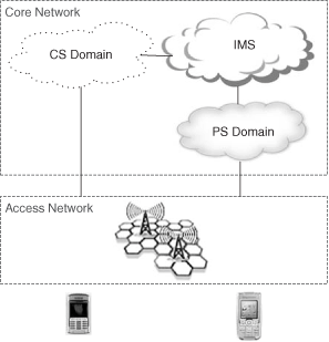
The UMTS architecture is broken down into access network (AN), which deals with the radio access, and the core network (CN). The core network can be further split into:
The Circuit-Switched (CS) Domain
The Packet-Switched (PS) Domain
The Internet Multimedia Subsystem (IMS)
The UMTS architecture is shown in Figure 24.1.
The CS Domain in UMTS is voice-centric (and video-centric) architecture similar to that of the second-generation (wireless) systems.
The PS Domain contains GPRS (General Packet Radio Service) [3GPP TS 23.060] infrastructure aimed at providing packet-based connectivity to mobile terminals. GPRS can be seen as a network providing IP connectivity. It does not provide any service itself beyond the pure connectivity. Services such as web, email, VoIP, and others have to be built on top.
The Internet Multimedia Subsystem is a network architecture that allows the provision of multimedia services. It relies on the IP connectivity provided by the PS domain. The IMS is based on the SIP protocol and architecture.
The complete solution for the support of IP multimedia applications consists of:
IMS-enabled User Equipments (UEs).
Access network and PS Domain providing IP connectivity.
The IMS network, composed of a number of functional elements.
Several releases of the 3GPP specifications have been produced so far. The IMS, which is the purpose of this chapter, was included in 3GPP release 5 (R5), and has been further developed in R6, R7, and now in R8 as well. Table 24.1 lists these releases and the main IMS features in each of them.
Table 24.1.
Release | Date | Info |
|---|---|---|
R5 | 2002 | IMS is introduced, focused mainly on GPRS access. |
R6 | 2004 | Enhancements to some interfaces |
IMS Group Management | ||
IMS Conferencing | ||
IMS Messaging | ||
Interworking between IMS and CS networks | ||
Interworking between IMS and non-IMS IP networks | ||
IMS charging | ||
PoC (Push to Talk Over Cellular) | ||
R7 | 2007 | Emergency calls |
Combinational services | ||
Enhancements for fixed broadband access to IMS. TISPAN R1 | ||
SMS over IP | ||
Evolution of Policy Control and Charging | ||
Voice call continuity | ||
R8 | IMS service brokering | |
Multimedia Priority Service | ||
Enhancements for TISPAN R2 | ||
Enhancements to support Packet Cable access | ||
Multimedia Conferencing | ||
Centralized IMS Service Control | ||
AS-MRFC media server control protocol |
The IP Multimedia Core Network Subsystem (IMS) is an architecture designed to let telecom operators provide IP multimedia communication services to their customers. [3GPP TS 22.228] defines the service requirements for the IMS.
The 3GPP specifications state that both the endpoints and the IMS network elements must have IPv6 connectivity. However, they may in addition support IPv4 in initial IMS implementations and deployments [3GPP TS 23.221].
IP connectivity from the endpoints to the IMS is achieved through the so-called IP Connectivity Access Network (IP-CAN).
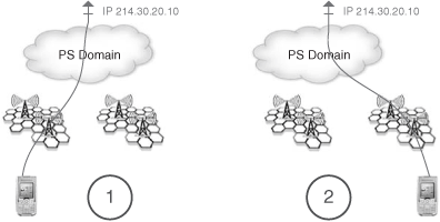
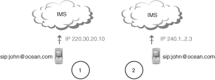
The main function of the IP-CAN is to provide the underlying IP transport connectivity between the user and the IMS. The IP-CAN is also responsible for dealing with the terminal mobility—that is, to maintain the service while the terminal moves, and to hide these moves from the IMS. The concept of “terminal mobility” should not be confused with “user mobility.” The former refers to coping with movements of the terminal while still presenting the same IP address to the upper layers; it is the responsibility of the IP-CAN. The latter refers to allowing a user identified by a logical identity (e.g., SIP URI) to be reachable even if he or she changes the IP address; it is achieved through the SIP registration mechanism at the IMS layer.
Figure 24.3 represents a terminal mobility scenario, and Figure 24.4 represents the user mobility case.
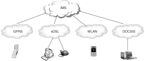
The IMS supports the principle of access independence so that IMS services can be provided over a variety of IP Connectivity Access Networks such as cellular (GPRS), xDSL, WLAN, cable, and so forth.
IMS Release 5 was fully orientated to its usage over a GPRS access. In Release 6, the possibility to use WLAN as an access network is introduced. In Release 7, specific aspects for the connection of xDSL access networks are also considered. Release 8 will tackle the support for Packet Cable accesses.
This principle is depicted in Figure 24.5.
Moreover, there is ongoing work [3GPP TR 22.892] to analyze the possibility of even considering the CS domain as another Connectivity Access Network so that even legacy terminals can gain access to a limited set of IMS applications. This is referred to as IMS centralized services.
This idea is also present in the ETSI TISPAN architecture for PSTN/ISDN emulation where legacy terminals[4] are offered basic telephony services delivered through IMS. The ETSI TISPAN architecture is examined in subsequent sections.
In mobile networks, there exists the fundamental concept of roaming. A user who wants to get mobile service needs to contract it with a mobile operator. The mobile operator offers mobile service to its customers in a defined country or region through its network. From the customer perspective, such a network is his or her home network. When the customer goes to another country or to another region where their operator does not have network infrastructure (specifically: no mobile radio coverage), they may still get mobile service through the mobile operator that offers service (i.e., mobile radio coverage) in that zone, provided that there is an agreement (a roaming agreement) between the customer’s home network operator and the visited network operator.
IMS has also been designed to support roaming so that mobile users that are in a visited network can still have access to multimedia services. [3GPP TS 23.221] defines two possible ways to achieve roaming:
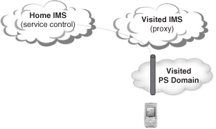
In the first approach, the IP connectivity is provided by the visited network. It is the visited network that provides the IP address for the UE. Therefore, the roaming UE contacts the visited IMS network through the visited access network. The IMS signaling will be passed from the visited IMS network to the home IMS network where the service control resides. This scenario is depicted in Figure 24.6.
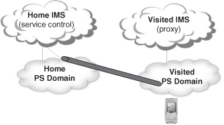
In the second approach, the Connectivity Access Network is composed by both visited and home network elements, being the home network that provides the IP address. In this case, the UE contacts the home IMS network directly—that is, without the visited IMS network’s involvement. This scenario is depicted in Figure 24.7.
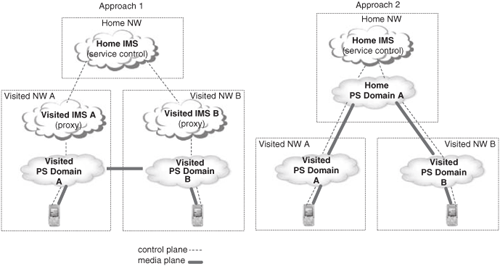
The first approach is better from the routing efficiency perspective because it does not force the media traffic to go all the way back to the home operator. In order to illustrate this idea, let us consider that both John and Alice, who belong to the same home IMS network, are roaming abroad in different visited IMS networks. John calls Alice. Figure 24.8 shows the path of both signaling and media traffic in each of the two approaches to achieve roaming.
It is important to highlight that in either of the two approaches for roaming, both the subscriber databases and the service control function reside in the home network. The service control function is in charge of invoking multimedia services on behalf of users based on subscription information. It will be further explained in subsequent sections.
There is a requirement for the IMS, in conjunction with the underlying IP access and transport network, to provide quality of service. Moreover, it is stated [3GPP TS 22.228] that the end-to-end QoS for a VoIP call using IMS must be at least as good as that achieved in today’s circuit-switched wireless networks.
Quality of service is seen as one of the aspects that telecom operators will use in order to differentiate their multimedia offerings from those of Internet service providers who in most cases do not have the means to provide QoS. This factor is particularly relevant when using limited-bandwidth accesses (e.g. wireless).
In order to offer quality of service, several aspects need to be considered:
The access network and the transport network must implement QoS mechanisms (packet classification, scheduling, admission control).
The operator may want to assure that the negotiated QoS at SIP/SDP level is enforced at the access and transport network level.
Resource reservation has to be realized in a coordinated manner with session establishment.
These three aspects amount to the need to use the architecture for quality of service that we presented in Chapter 21, which includes support for QoS policy control and QoS preconditions.
The IMS must be capable of supporting multiple multimedia applications within a single session. This requirement calls for a service control function in the IMS network that, based on subscription data, is able to identify per subscriber which applications need to be invoked for a call and in what order.
An important aspect is that the service control function is always located in the home network. So, in roaming scenarios, even if the IP connectivity is provided by the visited network, the IMS signaling (control plane) is routed back to the home network, where service control is applied. The decision to always base the service control (i.e., the service invocation) on the home network was one of the most crucial design decisions in the early days of IMS standardization. By having the service control reside in the home network, the architecture is made simpler, the interfaces between home and visited network are simplified, and the dependency for the delivery of services on the visited network is very much reduced.
The IMS must provide the same level of security, authentication, and privacy services as the existing circuit-switched and GPRS networks.
In particular, IMS provides authentication, confidentiality, and integrity services at two levels:
access: between the UEs and the IMS
network: between two IMS networks or between the nodes of the same IMS network
This concept is illustrated in Figure 24.9.
The Internet Multimedia Subsystem (IMS) is an architecture designed to let telecom operators provide multimedia communication services to their customers. 3GPP decided to base the IMS on the capabilities defined by IETF for multimedia session management—that is, on SIP. By doing so, it is expected that the Internet flexibility for delivering services can be brought to the telecom environment, and that the merger of mobile communications and Internet will create new services and business opportunities.
Nevertheless, given that the scope of IMS is centered on its use by telecom operators, the resulting IMS architecture makes some assumptions and addresses some requirements that are not applicable to the Internet at large. As an example, it is assumed that there is a tight relationship between the operator and the subscriber and that the operator’s network is composed by a set of trusted nodes. Moreover, it is also assumed that quality of service and charging are crucial aspects of the solution.
Throughout this chapter, we will discover that the IMS, in addition to the core SIP specification, also incorporates many SIP extensions and SIP network functions. In some cases, these extensions already existed; in other cases, they have been defined based on specific IMS requirements. We will see that the IMS architecture is not, as a matter of fact, very different from the architecture of the full-fledged controlled SIP network that we saw in Chapter 23 (though the IMS elements are given new and sometimes obscure names).
It is important to highlight the fact that the architecture defined by 3GPP is a functional one.
Nothing precludes the operator from deploying several of those functions in the same box. Moreover, it is not surprising to see initial IMS deployments with just one box (or two, for redundancy reasons) including almost all the components.
The IMS architecture is defined in [3GPP TS 23.228].
Next we will present the different functional elements that compose the IMS architecture.
We learned throughout the book that the very basic SIP infrastructure consists of a SIP registrar and a SIP proxy. These two elements grouped together are typically referred to as a SIP server, and are necessary to provide user mobility and to route terminating calls to the user. Therefore, the first IMS element is the user’s home SIP server—or, in IMS terminology, the Serving Call Session Control Function (S-CSCF).
The S-CSCF incorporates basic registrar and proxy functionality, but adds some additional functions. The main additional functions are described next.
When the user registers with the S-CSCF, the S-CSCF may authenticate him or her. For that purpose, the S-CSCF contacts an authentication server from which it derives the authentication parameters that apply for this user (e.g., the authentication challenge, the expected response, etc.). The S-CSCF then challenges the user to provide authentication credentials. Once the user responds, the S-CSCF checks that the provided credentials are correct. The S-CSCF and the UE use SIP digest authentication with Authentication and Key Agreement (AKA) [RFC 3310]. The AKA protocol will be explained in subsequent sections.
The authentication server used by the S-CSCF is called Home Subscriber Server (HSS). It holds the shared secret for each subscriber, among other subscriber data that we will see later on. The interface between S-CSCF and HSS is based on the Diameter base protocol.
When the user registers and the authentication is confirmed, the S-CSCF again contacts the HSS in order to retrieve the user profile. The user profile contains information about the media types that the user is authorized to use, and about the services that are to be applied to the user (i.e., about the application servers that will need to be contacted whenever the user issues a request).
Therefore, the HSS, in addition to storing secret keys, also stores the service profile for each user.
In IETF SIP, the end user needs to register in order to receive calls. However, the user might make outgoing calls without being registered. Moreover, he or she might even direct outgoing calls toward the recipient’s SIP server without involving his or her own SIP server at all.
On the other hand, 3GPP mandates that the user also needs to be registered in order to make outgoing calls, and originating requests have to go through the user’s S-CSCF. The main reason for that is to allow service execution and media authorization, in accordance with the user’s profile downloaded from the HSS at registration, to be applied to the user when he or she originates calls. Later on, we will see how originating calls are forced through the S-CSCF.
The service profile downloaded from the HSS contains a list of Application Servers (ASs) (identified by their URI) and some filtering rules. The filtering rules allow the S-CSCF to determine when received SIP requests need to be routed to a particular Application Server. In this way, customized services can be applied to the users, and a very neat separation is enforced between the basic SIP functions (S-CSCF) and the enhanced service logic (AS).
Service control aspects are further detailed in section 24.4.4.
The user profile in the HSS, which is downloaded at registration, contains the list of media types that the user is allowed to utilize in multimedia sessions.
When an attempt to set up a session reaches the S-CSCF, the S-CSCF can reject the request if the session includes a nonallowed media type for the user (e.g., video).
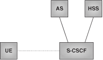
Figure 24.10 depicts the three IMS entities discussed so far: S-CSCF, HSS, and AS.
We have seen that the S-CSCF incorporates the main functions of a home SIP server. However, there are some other needed SIP proxy functions that we have not yet mentioned.
One of the aspects that the S-CSCF deals with is the authentication of the users. In addition to the authentication itself, it is necessary to provide integrity and confidentiality protection between the user and the network. In Chapter 14, we saw the possibility to use TLS between the user and his or her SIP server in order to provide those functions. We mentioned that IPsec might be used as well. IMS specifies the use of IPsec security associations (SA) between the user and the network. Thus, we need a network function for maintaining such IPsec security associations.
Another function that is very important, especially when dealing with bandwidth-limited-access networks such as cellular, is the signaling compression. There is, then, the need to have a network function responsible for compressing the SIP messages as they are sent to the user, and for uncompressing them when they are received by the network.
The IMS network must have the capability to prohibit the use of specific codecs. For instance, some IMS networks might want to prohibit the use of codecs that consume a lot of bandwidth. This is particularly important when using IMS with cellular access, where bandwidth is limited.
In policy control architectures, such as the one we saw in Chapter 21, there is the need to have a QoS-enabled proxy that is responsible for interacting with the PDP in order to retrieve the authorization token and pass it to the user in the SIP signaling. Such a token is later on used by the endpoint to obtain authorization for resource reservation at media level.
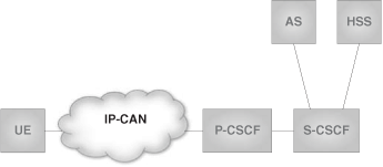
Some of the functions mentioned above can benefit from closeness to the access network, whereas others require a significant amount of processing resources. Therefore, it was decided to logically separate these functions from the home SIP server and define another IMS functional element to cope with them. Such an element is a SIP proxy that, in IMS terminology, is called the P-CSCF (Proxy Call Session Control Function). It is the first contact point for users within the IMS, both for outgoing and incoming requests. Thus, our previous architecture in Figure 24.10 should rather look like Figure 24.11.
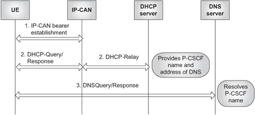
At this point, and given that the P-CSCF is the “single point of contact” for the user in the IMS, some readers might wonder how the user can determine its address. Two methods have been standardized for P-CSCF discovery :
Use DHCP to provide the user with the domain name of a P-CSCF and the address of a DNS server that is capable of resolving the P-CSCF name. See Figure 24.12.
Use means provided by the IP-CAN. Some IP-CANs provide the capability to derive the P-CSCF address as part of the access bearer establishment process.
Another approach that, though not standardized, is used in some deployments consists of manually configuring the name or address of the P-CSCF in the terminal.
Once assigned to a user, the P-CSCF does not change while the user remains connected to the access network.
An interesting aspect about the IMS architecture is the fact that it explicitly addresses network topologies where more than one S-CSCF may be needed. Moreover, users are not statically assigned a particular S-CSCF. The association between user and S-CSCF is dynamic and based on a number of criteria such as:
S-CSCF capabilities that users need, according to their profile in HSS
Operator’s preferences on a per-user basis
Load distribution
As we can see, the first and second criteria rely on using some kind of user-specific information in order to take the S-CSCF assignment decision.
Thus, two challenges are posed to the IMS architecture:
How to dynamically assign, at registration time, an S-CSCF to a user?
If users are distributed among several S-CSCFs based on user-level criteria, how can the IMS route incoming requests to the appropriate S-CSCF?
The solution to these challenges is based on having an additional SIP proxy function that:
Receives both the registrations and the incoming requests.
Interrogates the HSS to receive assistance for subsequent routing to the proper S-CSCF.
Forwards the SIP requests to the corresponding S-CSCF.
Unsurprisingly, this new SIP proxy function is called, in IMS terminology, the Interrogating Call Session Control Function (I-CSCF).
The I-CSCF acts as an edge proxy, and requests are routed to it based on the home domain name. The I-CSCF is the entity in an IMS network that stands for the specific IMS domain (e.g., ocean.com) to which all registrations and incoming calls are directed.
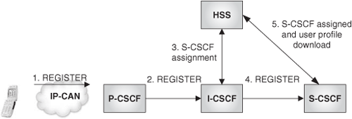
In the registration case, the I-CSCF will interrogate the HSS for specific S-CSCF capabilities that are required for the registering user. When the I-CSCF has received that information from HSS, it will decide to which S-CSCF to route the REGISTER message. The I-CSCF uses internal configuration to select the S-CSCF. In order to force the routing to the appropriate S-CSCF, the I-CSCF will include the S-CSCF’s name or address in the Route header field of the REGISTER request. Once the user is registered, the HSS will need to be informed of which S-CSCF the user has been assigned. This is important to cope with the routing of incoming requests, as we will see next. It is the assigned S-CSCF itself that, as soon as the authentication is successfully completed, informs the HSS about the assignment.
Figure 24.13 shows this scenario, which now includes all the CSCF types (S-, P- and I-) in action.
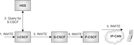
In the second case, when the I-CSCF receives an incoming request for john@ ocean.com, the I-CSCF will interrogate the HSS for John in order to retrieve the name (or address) of the S-CSCF that John was assigned at registration time. Once the I-CSCF has obtained that information, it will include the S-CSCF name or address in the Route header of the request so that the request reaches the S-CSCF.
This scenario is shown in Figure 24.14.
The SIP proxies that we saw before do not, just by themselves, deliver any added-value services. IMS applications are implemented in SIP application servers with the help, if needed, of media servers.
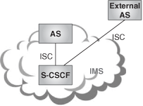
In the IMS architecture, it is the S-CSCF that, based on subscription information downloaded from the HSS, decides which Application Servers need to be involved and in what order, to handle a particular request. If the S-CSCF determines that an Application Server (AS) needs to be involved, the S-CSCF delegates control to that AS. The interface between the S-CSCF and the AS is SIP based, and is referred to as ISC (IMS Service Control).
In the IMS terminology, the media server function is called MRF (Media Resource Function). The MRF is further split into two components:
MRFP (Media Resource Function Processor)
MRFC (Media Resource Function Controller)
The Media Resource Function Processor provides the media-processing functions such as:
media stream source
media stream processing
mixing of media streams
and offers its resources to be controlled by the MRFC.
The Media Resource Function Controller represents the control part associated with the managements of media resources. It uses a MEGACO-based protocol to control the MRFP.
Figure 24.16 shows this architecture.
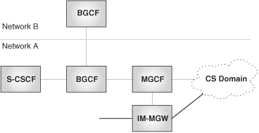
In order to interwork with the PSTN or PLMN, the IMS architecture also includes a gateway function. This function is split into MGC and MG according to the ideas discussed in Chapter 18. According to IMS terminology, the MGC is called MGCF (Media Gateway Control Function), and the MG is called IM-MGW (Internet Multimedia Gateway).
In addition to these functions, the IMS introduces a new SIP proxy function, the BGCF (Border Gateway Control Function), which is used in PSTN/PLMN breakout scenarios (call from IMS to PSTN). The reader may remember from our discussion in Chapter 18 that in these scenarios, there was a need to determine which gateway to use for the breakout. The BGCF is a SIP proxy responsible for selecting the gateway to be used for the breakout.
The IMS does not further specify how the BGCF obtains the information on which to base the decision to route to a particular gateway (it might be static configuration, based on a routing protocol, and so on).
If the breakout is not to occur in the operator’s own IMS network, the BGCF may also select on which other IMS network the breakout is to happen, and route the call to a BGCF in the other network.
The architecture for PSTN interworking is shown in Figure 24.17.
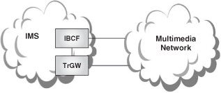
An operator’s IMS network can also interwork with other operators’ IMS networks or with other SIP-based multimedia networks. Border control functions may be applied in these cases, based on operator preference.
The border control functions are split, in the IMS architecture, into control plane and media plane. The control plane component is called Interconnect Border Control Function (IBCF), and the media component is called Transition Gateway (TrGW).
Some of the IBCF’s functions are:
As the reader can note, these functions are the ones that correspond to an I-SBC that we saw in Chapter 22. IBCF is the name that the IMS standards give to these functions, whereas I-SBC is a term coined by the industry to provide similar functions in SIP networks.
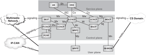
With all we learned in the previous sections, we are now in a position to draw the architecture of the Internet Multimedia Core Network Subsystem and to understand its rationale. We have included the name that 3GPP gives to the interfaces between the functional elements. All the depicted interfaces are based on SIP, except for:
Mn and Mp: based on MEGACO
Cx and Sh: based on Diameter
The reference IMS architecture is shown in Figure 24.19.
Next we present some representative IMS call flows that illustrate the IMS functions discussed so far.
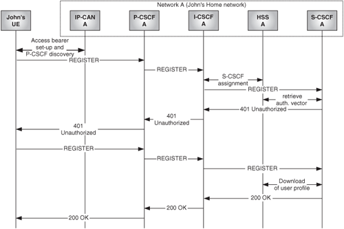
The call flow in Figure 24.20 shows John registering in his home network (network A).
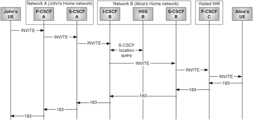
The call flow in Figure 24.21 shows John setting up a session with Alice. John’s home network is network A. Alice’s home network is network B.
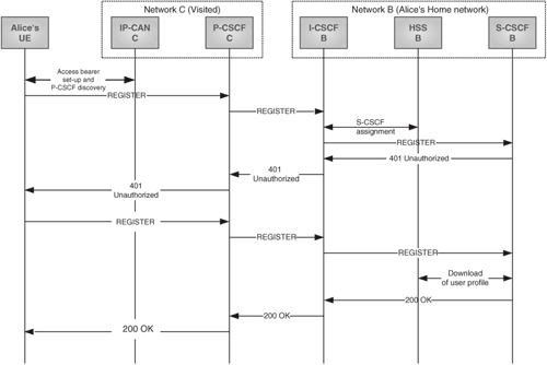
In the following call flows, we consider Alice to be roaming in network C. We have considered a roaming approach such that Alice gains IP connectivity from network C, and her first point of contact in the IMS network is the P-CSCF in network C.
Figure 24.22 shows Alice registering in her home network (network B) while she is roaming in network C.
Figure 24.23 shows a call from John to Alice while Alice is roaming in network C.
A detailed explanation of various other IMS call flows can be found in [3GPP TS 24.228].[5]
In the previous section, we have seen that the IMS architecture implies certain additional functions on top of the architecture of a basic SIP network. Next we will describe in more detail some fundamental IMS concepts, and highlight what differences they represent as compared with a basic SIP network.
In a basic SIP network, the end user is typically assigned a public identity and some security credentials. The public identity typically has the form of a SIP URI such as [email protected]. When John registers to his SIP server, he uses his public identity, which then is authenticated by the server. The public identity is also employed by other users in order to request communication with John.
In IMS, the end user is assigned two identities instead of just one. The first one is called the Private User Identity (IMPI), and represents the identity that is authenticated by the network. The second one is called Public User Identity (IMPU, sometimes also referred to as PUI), and is the one employed by other users to request communication with John.
In addition to public and private user identities, the IMS also defines support for GRUUs (Globally Routable User URIs). GRUUs were analyzed in Chapter 15.
The Private User Identity is a unique global identity defined by the home network operator, which may be used within the home network to identify the user’s subscription from a network perspective. It is valid for the complete duration of the user’s subscription with the home network.
It is used mainly for authentication purposes during the registration phase. It can also be used for administration and charging purposes. It is not used for routing purposes.
The user does not have access to the Private User Identity. It is stored in the HSS and in the ISIM (IMS Subscriber Identity Module) application [3GPP TS 31.103]. The ISIM application resides on the UICC (Universal Integrated Circuit Card), which is a tamper-resistant device that can be inserted or removed from the User Equipment [3GPP TS 31.101].
The Private User Identity takes the form of an NAI, network access identifier [RFC 4282]. An example of Private User Identity is:
In order to use the IMS, a user is assigned one or more Public User Identities. The Public User Identity is used by any user for requesting communications to other users. For example, it might be included on a business card.
The Public User Identity must be registered in the network before the user can start using the IMS.
The Public User Identity takes the form of a SIP URI or a TEL URI. It is stored in the HSS and on the ISIM.
Two examples of Public User Identity are:
sip: [email protected] and tel:[email protected]
IMS security encompasses two aspects:
Access Security, described in [3GPP TS 33.203]
Network Domain Security, described in [3GPP TS 33.210]
This term refers to the provision of security services such as authentication, integrity, and confidentiality for the SIP signaling path between the user and the IMS network.
Mutual authentication between the user and the network is based on the UMTS Authentication and Key Agreement (AKA) protocol. As we saw in Chapter 14, SIP uses the HTTP Digest mechanism for authentication. Therefore, there is a need to map the AKA parameters onto HTTP Digest authentication. Such a mapping is described in [RFC 3310].
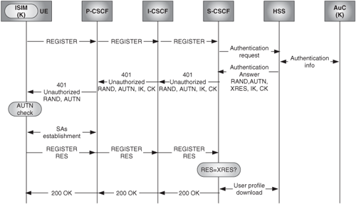
The AKA protocol works as follows:
The ISIM and the network share a long-term secret (K).
The network produces an authentication vector based on K and a sequence number SQN. The authentication vector contains:
A random challenge (RAND)
An authentication token (AUTN)
The expected authentication response (XRES)
Two session keys: an integrity key (IK) and a cipher key (CK)
The authentication vector is downloaded from the HSS to the S-CSCF when the first REGISTER is received by the S-CSCF.
The S-CSCF creates an authentication request containing RAND, AUTN, IK, and CK, and sends it to the user in the 401 (Unauthorized) response.
The user verifies with the ISIM that the AUTN is correct. If the AUTN is correct, the network has been authenticated. The user then produces an authentication response using K and RAND, and sends the result (RES) to the S-CSCF in a second REGISTER message.
The S-CSCF compares RES with XRES. If they match, authentication is successful.
As a by-product of the authentication process, two session keys have also been obtained (IK and CK). The UE and the P-CSCF use these session keys to secure the communication in the access by establishing two pairs of IPsec ESP security associations[6] through which the traffic is sent encrypted and integrity protected. Once the SAs are established, the P-CSCF will identify all the SIP requests coming through the corresponding SA as pertaining to the authenticated user.
Figure 24.24 depicts the whole process of authentication and SAs establishment. For brevity, the S-CSCF assignment process is not shown in the diagram.
NDS refers to the provision of authentication, confidentiality, integrity, and replay protection between different IMS networks (security domains) or between nodes within the same security domain.
In order to achieve NDS, security gateways (SEG) are deployed in the interconnecting networks. Each SEG is responsible for setting up and maintaining security associations with its peer SEGs. The SAs are negotiated using the Internet Key Exchange (IKE) protocol defined in [RFC 4306]. The authentication is based on preshared secrets.
IMS uses the identity management procedures based on the P-Asserted-Identity that were described in Chapter 20 [RFC 3325]. The IMS home network is considered a trust domain.
Privacy mechanisms applicable in IMS are defined in [RFC 3323] and [RFC 3325], and were discussed in Chapter 20.
One of the most interesting concepts that IMS introduces as compared with a plain SIP network is that of the IM call model and service control function. The IM call model is described in [3GPP TS 23.218].
In IETF SIP, there is no standardized mechanism for service invocation. Following the IETF approach, a user might get access to multimedia services in different ways. For instance, the user might force his or her requests to traverse a particular Application Server (by introducing the AS URI in the Route header of outgoing requests), or they might rely on some proxy to do that function for them. But these mechanisms are not standardized.
Defining such mechanisms is critical in order to be able to provide users with a consistent service proposition that may be composed of different applications executing for the same call on behalf of the originating or the terminating user.
Moreover, standardizing those mechanisms is also crucial so that the IMS users can leverage applications deployed in the home operator, in the visited operator, or in a third party. The standardization of those mechanisms and of the interface between the S-CSCF and the Application Servers (ISC) is seen as a key element for the success of IMS. The IMS without services on top has very little value (if any), and operators cannot expect to themselves develop all the possible services that users may demand in the future. Telecom operators and Internet players may need to partner at some time, and the service control interface, or a higher-level interface (e.g., web services) may be the key for the integration.
Figure 24.25 shows an operator’s IMS network through which users can access Application Servers owned by the IMS network operator, or external Application Servers not owned by the IMS operator (i.e., from another operator or a third party).
The IMS standards divide the call execution flow into two parts: originating and terminating. Associated with each part is a service control entity:
The service control in the originating part is done by the home S-CSCF of the originator of the request.
The service control in the terminating part is done by the home S-CSCF of the recipient of the request.
Therefore, the originating S-CSCF can invoke services on behalf of the requestor, and the terminating S-CSCF can invoke services on behalf of the recipient. This is depicted in Figure 24.26.
The services to invoke in both the originating and terminating side are defined by subscriber data stored in the HSS. This data is downloaded at registration.
Such data consists of a list of so-called Initial Filter Criteria (iFC). An iFC defines a set of conditions that, when met, will force the S-CSCF to delegate the control to an AS whose URI is also part of the iFC. The conditions can be based on whatever combination of values of SIP methods, SIP headers, SDPs, and so forth are present in the incoming request.
If more than one iFC is provisioned, this means that more than one AS may need to be involved in the processing of the request. Therefore, the subscription data also needs to specify in what order the Application Servers need to be invoked.
Next is an example of how service control works in an originating scenario. John is subscribed to four services, offered in respective Application Servers. John’s user profile in the HSS contains four iFCs, one for each service. His profile also contains the iFCs’ priority. The iFC with the highest priority is iFC1, whereas iFC4 has the least priority:
iFC1 > iFC2 > iFC3 > iFC4
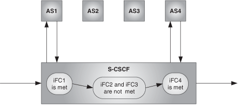
When a new originating request reaches the S-CSCF, the S-CSCF will check John’s service profile, and will determine if some of the iFCs are met. Imagine that iFC1, associated with AS1, is met. Then the S-CSCF forces the routing to AS1 and back to the S-CSCF.[7] Once the request is back to the S-CSCF, the S-CSCF will continue evaluating the remaining iFCs of lower priority for the new request that comes from the AS. So the S-CSCF will check if iFC2 is met, then iFC3, and then iFC4. Let us assume that in this particular case, iFC2 and iFC3 are not met, but iFC4 is. In that case, the S-CSCF will contact AS4. When the request comes back from AS4, the S-CSCF will know that there are no more iFCs to evaluate, and thus it will forward the request to the next network element. This is shown in Figure 24.27.
The charging architecture, charging principles, and charging data for IM CN subsystem are described in [3GPP TS 32.240] and [3GPP TS 32.260].
The IMS supports offline charging, online charging, and charging correlation. Charging correlation is briefly explained in the next section.
Offline charging is a mechanism where charging information does not affect, in real-time, the service rendered.
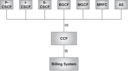
All the IMS elements (P/I/S-CSCF, BGCF, MGCF, MRFC, SIP AS) can generate offline charging information. The charging information is sent via Diameter protocol to a Charging Collection Function (Rf interface). The CCF processes the received information, and generates billing records that are sent via FTP to the billing system (Bi interface). This is depicted in Figure 24.28.
Online charging is a mechanism whereby charging information can affect, in realtime, the service rendered. Therefore, a direct interaction of the charging mechanism with the control of the network resource usage is required.
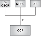
The S-CSCF, AS, and MRFC support a Diameter-based charging interface (Ro) toward an Online Charging Function (OCF). This is shown in Figure 24.29. The OCF is a functional element capable of charging in realtime. It performs mainly three functions:
Charging control
Account balance management
Rating
The OCF itself is not part of the IMS CN architecture. It is a horizontal function—that is, it can be used in other, non-IMS-related scenarios as well. The OCF is defined in [3GPP TS 32.296].
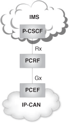
The IMS defines architecture for policy control that is similar to the one that we examined in Chapter 21. The main difference comes from the fact that, since R7, the architecture for policy control and charging control has converged into just one architecture. Therefore, there is no longer a PDF or a CRF—both are merged into a PCRF (Policy and Charging Rules Function).
Likewise, there is no longer a PEP (Policy Enforcement Point) or a TPF Transport Plane Function)—both are merged into the PCEF (Policy and Charging Enforcement Function).
Moreover, COPS is no longer used. The new Gx and Rx interfaces are used; they are based on Diameter.
This is depicted in Figure 24.30.
In addition to policy control and charging control, this architecture also supports charging correlation. Charging correlation consists of exchanging, through the PCRF, the charging identifiers generated at both IMS and IP-CAN levels so that the charging records generated at both levels can be correlated for billing purposes.
Charging control has not been explained in this book so far. It refers to a function that is targeted mainly at controlling the way in which IP flow-based charging on the traffic plane is realized. For that purpose, the PCRF is capable of installing rules in the traffic plane gateway, e.g., in the GPRS Gateway Support Node (GGSN).[8]
An in-depth analysis of policy and charging control is out of the scope of this book. Interested readers are referred to [3GPP TS 29.214] and [3GPP TS 29.212].
In this section, and in order to make the book coverage on SIP as complete as possible, we will explain some new SIP extensions that are introduced due to IMS requirements.
We saw earlier in this chapter that outgoing requests from a UE need to traverse the originating user’s S-CSCF so that the S-CSCF can apply services on the user’s behalf. We also learned that S-CSCFs are assigned to the users dynamically at registration.
Therefore, there is an issue that we have not yet tackled: How does the UE know which S-CSCF to use for originating requests, and how to get there? The UE has mechanisms (e.g., DHCP/DNS) to determine what P-CSCF to use for sending originating requests, but what about the S-CSCF?
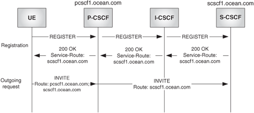
This issue is resolved by a new SIP extension defined in [RFC 3608]. This extension defines the new Service-Route header field, which is generated by the registrar (i.e., the S-CSCF in the IMS case) and is included in successful responses to the REGISTER message. The Service-Route header conveys the name of the home service proxy (i.e., the S-CSCF) where the UA must direct its requests.
Once the UA has received the response (i.e., the 200 OK) to the REGISTER, it will include both the P-CSCF name and the S-CSCF name in the Route header of all outgoing requests.
This is shown in Figure 24.31.
During our discussion of the IMS architecture, we said that the P-CSCF had to be involved in all originating and terminating requests. Because they are the elements that terminate the security associations toward the UE, it is critical that all traffic from and to the UE goes through them.
The originating scenario presents no difficulties—that is, we already saw that the UE can learn the address of the P-CSCF, and therefore force the routing of all outgoing requests through it.
In the terminating case, the terminating S-CSCF needs to know the name/address of the recipient’s P-CSCF so as to force the routing through it. The question now is: How can the S-CSCF know that information?
The answer to this issue comes again from a new SIP extension defined in [RFC 3327]. This extension defines the new Path header field, which the originating P-CSCF adds to the REGISTER message when the user registers. Therefore, as soon as the user is registered, the registrar (i.e., the S-CSCF) has the information as to the correct P-CSCF to which terminating requests to that user should be addressed.
This is shown in Figure 24.32.
[RFC 3455] defines a number of private SIP extensions to cope with specific IMS requirements. Next we briefly describe those extensions.
When a user roaming in a visited network attempts to register, there is a need to convey the information about the visited network to the home S-CSCF so that it can check if there exists a roaming agreement with the visited network. In order to convey this information, a new private header has been defined that contains a text string that identifies the visited network. The P-CSCF in the visited network adds this header into the REGISTER message that is sent to the home S-CSCF Example:.
P-Visited-Network-ID= “Vodafone Italy”
There are cases, especially when a wireless-access network is used, when the services to apply may depend on the technology of the access network or the location of the user (e.g., the cell from which a call or other IMS service originates). The new private P-Access-Network-Info header is capable of conveying that information from the UE to the IMS network. This header is populated by the UE based on the information it gets from other sources (for example, radio signaling).
The IMS architecture is distributed. Many functional elements are able to generate charging information. This charging information needs to be sent to either a Charging Collection Function (CCF), in the case of offline charging, or to an OCF (Online Charging Function), in the case of online charging. The addresses of these entities are conveyed via SIP signaling in the P-Charging-Function-Address header.
The CCF and OCF addresses are stored in the HSS, and are conveyed to the S-CSCF via the Cx interface. The charging function addresses are passed from the S-CSCF to the rest of the IMS entities in the home network so that they can know where to send the charging information.
The P-Charging-Vector header includes charging information that facilitates the task of the offline and online charging systems.
It includes three parameters:
IMS Correlation ID (ICID)
Access Network Charging Information
Inter Operator Identifier (IOI)
The IMS is a distributed system. Many functional elements (e.g., P-CSCF, S-CSCF, AS, and so on) may be involved in processing a particular call or other IMS service. These elements may generate accounting information for the online and offline charging systems. The task of the charging systems would be much easier if they could easily identify different accounting information from different elements as pertaining to the same call. The IMS network facilitates this by providing a correlation ID.
The first IMS entity that is involved in a call will generate a globally unique ICID. It then passes the ICID in the SIP signaling, as part of the P-Charging-Vector header, to the rest of IMS entities in the IMS domain.
This parameter is provided by the access network via Gx and Rx to the P-CSCF, which includes it in the P-Charging-Vector header. It helps correlate charging information generated at IMS level, and the corresponding one generated at access network level (e.g., GPRS).
We saw in previous sections that an IMS user may be associated with more than one Public User Identity. When the user sends a REGISTER message to the network in order to register a particular Public User Identity, the S-CSCF responds with a 200 OK that includes the P-Associated-URI header that lists all the associated Public User Identities.
The presence of a URI in the P-Associated-ID does not mean that such a URI is registered, only that it is associated with the Public User Identity that has been registered.
An IMS user may have various service profiles, each of them with its set of Public User Identities. For instance, John might have a personal profile with the URI: sip: [email protected], and a business profile with the URI: sip:[email protected]. The different profiles might have different services associated.
When John receives an incoming call or request, he might want to know if the caller is calling to his personal or business identity. For instance, he might want to apply a different ringing tone in each case, or perhaps his willingness to accept the call depends on what case it is. Unfortunately, there is no way to do this with plain SIP. Let us recall that when the call reaches the S-CSCF, the Request-URI does contain the original target identity, but the S-CSCF, after querying the location service, replaces it with the recipient’s contact address, so the recipient does not have access to the identity the call was addressed to.
In order to overcome this problem, a new SIP header, the P-Called-Party-ID, is introduced by the S-CSCF in the requests toward the called party. The P-Called-Party-ID has the same value as the Request-URI of the terminating request received by the S-CSCF.
IMS being essentially a SIP-based multimedia network, most of the SIP services that we saw in previous chapters can be, in principle, offered over an IMS infrastructure. Furthermore, the combination of multimedia and wireless mobility creates new, compelling service scenarios. In many cases, and true to the end-to-end nature of SIP, IMS applications are located in the endpoints. That is the case of gaming applications, for instance. In other cases, the applications sit on Application Servers on top of the IMS network. An advanced IP telephony application such as “Follow-me” might belong to this category. Hybrid situations are also common.
The aim of 3GPP is not to standardize all the applications, but rather, to provide service capabilities. Nevertheless, there are some important applications that have been specified both by 3GPP and/or OMA, given the need to ensure interoperability and interworking across different operators’ networks. Examples are:
The presence service
IMS messaging
The Push to Talk over cellular (PoC) service
The multimedia telephony services
Combinational services
Global Text Telephony (GTT)
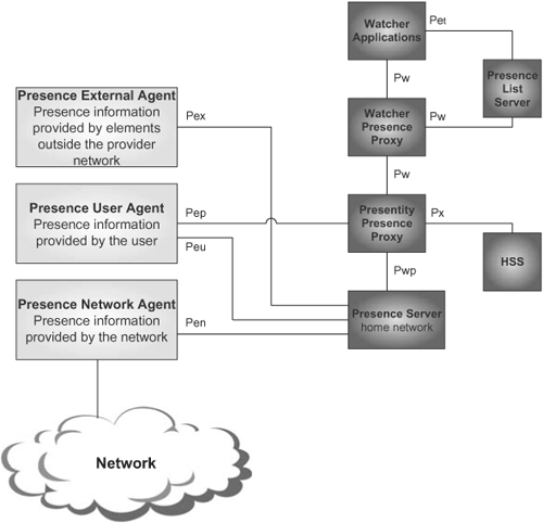
[3GPP TS 22.141], [3GPP TS 23.141], and [3GPP TS 24.141] define the IMS presence service that is based on the IETF SIP/SIMPLE. 3GPP defines a full-fledged, functional architecture for presence that is mapped to the IMS functional entities.
Figure 24.33 shows the elements and interfaces in the presence service architecture defined by 3GPP, whose explanation is outside of the scope of this book.
The requirements for IMS messaging are defined in [3GPP TS 22.340], and the technical realization is described in [3GPP TS 24.247].
IMS supports two types of online messaging services, which are referred to as:
Immediate messaging
Session-based messaging
In immediate messaging, the user can both send and receive messages without any prior actions. In session-based messaging, the user joins a messaging session before the message exchange can take place.
Immediate messaging is supported using just the SIP MESSAGE method (see Chapter 16), whereas session-based messaging is supported using SIP to establish the session, and MSRP for the messaging transfer in the media plane (see Chapters 10 and 16).
Push to Talk over Cellular (PoC) service is a two-way form of communications that allows users to engage in immediate communication with one or more other users. The user experience for the PoC service is similar to a “walkie-talkie” application. When a user wants to initiate a talk session with an individual user or with a group of participants, he or she needs to press a button and then talk.
The implementation for this service is based on SIP Application Servers (and Media Resource Functions) sitting on the IMS network.
[OMA-AD-PoC] defines the architecture of the PoC service on top of a SIP/IP infrastructure. Such an infrastructure can be based on 3GPP IMS, as described in [3GPP TR 23.979].
The IMS Multimedia Telephony Service ([3GPP TS 22.173] and [3GPP TS 24.173]) allows multimedia conversational communications between two or more users, including different types of media such as speech, video, or other types of data. Associated with this service are a number of supplementary services, similar—but not identical—to the ones existing in 2G mobile networks and in ISDN.
The IMS multimedia telephony supplementary services are:
Originating Identification Presentation (OIP)
Originating Identification Restriction (OIR)
Terminating Identification Presentation (TIP)
Terminating Identification Restriction (TIR)
Communication Diversion (CDIV)
Communication Hold (HOLD)
Communication Barring (CB)
Message Waiting Indication (MWI)
Explicit Communication Transfer (ECT)
The specification for these services is based on the TISPAN specification for PSTN simulation services [ETSI TS 181 002].[9]
The implementation for this service is based on SIP Application Servers (and media servers) sitting on the IMS network.
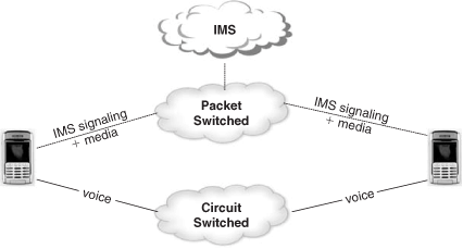
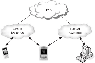
It will yet take some time for mobile operators to replace the existing cellular circuit-switched voice service with cellular VoIP for the whole customer base. The reasons are technical (need for resource optimization, quality of service, and handset support) and commercial (huge investment in circuit-switching technology already done, need to make new investments on packet-switching infrastructure). However, in the meantime, the IMS network can be used to enable other services (ones that are not so bandwidth demanding) for wireless users. The possibility then arises to combine the cellular circuit-switched voice with other new fancy services such as picture sharing, video sharing, enriched alert, and so forth. The voice part would be carried by the Circuit-Switched domain, and the data part would be handled by the Packet-Switched domain and the IMS network. The voice part of the call and the data part of the call would be tied together into a single communication context at the terminal. Such types of services are referred to as Combinational Services [3GPP TS 22.279], [3GPP TS 23.279], and [3GPP TS 24.279].
Figure 24.34 depicts this idea.
Combinational services do not necessarily require network-based service logic. It is just the endpoints that need to have the proper service logic in order to generate the context that allows us to correlate the CS and IMS sides of the communication.
On the other hand, the terminal and the access network must facilitate simultaneous circuit-switched and packet-switched access. Hence, the access network must be UMTS (allows for simultaneous CS and PS access) or support Dual-Transfer Mode (DTM).
The requirements for GTT are defined in [3GPP TS 22.226]. A possible utilization of the IMS architecture to deliver GTT services is described in [3GPP TS 23.226]. [3GPP TS 23.226] also defines other non-IMS-based architectures that can be used to deliver this service.
Global Text Telephony is a feature that adds the capability to use a real-time, character-by-character, text-conversation component in a session.
GTT in IMS is supported using SIP for the session management. Text is encoded according to [ITU T.140], and transported over RTP using the RTP text payload as specified in [RFC 4103]. This allows conversation in a selection of simultaneous media, such as text, video, and voice.
We have just seen some of the standardized IMS services. Nevertheless, the strength of SIP and IMS is that they offer the capability to create new communication services limited only by our imagination.
TISPAN (Telecoms and Internet converged Services and Protocols for Advanced Networks) is a standardization body within ETSI (European Telecommunications Standards Institute) that specializes in fixed networks and Internet convergence.
TISPAN’s aim is to define the architecture and provide technical specifications for a Next Generation Network (NGN).[10] TISPAN Release 1 was published in December 2005. The main focus of Release 1 was to define the reference architecture [ETSI ES 282 001] for the NGN, and to demonstrate its feasibility by specifying the details for two main objectives:
To enable delivery of the services supported in a 3GPP IMS to broadband fixed lines.
To enable PSTN/ISDN replacement (in whole or in part).
Interestingly enough, TISPAN has chosen the 3GPP IMS architecture (thus, a SIP-based network) to provide some core subsystems within the architecture. TISPAN and 3GPP have worked collaboratively in IMS R7 in order to specify wire-line access for an IMS network (let us recall that up to R6, 3GPP was focused mainly in wireless access).
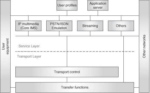
So, 3GPP chose SIP as the basis for a wireless multimedia network (IMS), and now TISPAN chooses to adapt the IMS infrastructure (i.e., SIP based) for the evolved fixed network. Thus, both 3GPP and TISPAN are setting the grounds for a truly access-independent next-generation multimedia network that is based on SIP! Figure 24.35 shows the TISPAN reference architecture.
It comprises two layers:
the transport layer
the service layer
The transport layer provides the IP connectivity functions both in access and core, and the control functions associated with the transport (IP address assignment, resource and admission control, and so on). [ETSI ES 282 004] and [ETSI ES 282 003] describe the functional architecture for the transport-layer control functions. The service layer is split into a set of subsystems, each of them specialized in a particular service area, plus a set of common components.
The subsystems are:
The core IP multimedia subsystem, targeted at providing multimedia services to TISPAN users [ETSI ES 282 007].
The PSTN/Emulation subsystem, aimed at providing PSTN features to legacy terminals over a SIP-based network, [ETSI TS 182 012] and [ETSI TS 183 043].
Streaming subsystem, to provide RTSP-based streaming services.
Other subsystems.
The common components are:
User profile, where the user subscription information is stored (equivalent to the IMS HSS concept).
Application Servers, where applications reside.
Subsystems 1 and 2 are based on the 3GPP IMS, but slightly adapted to cope with new requirements and access types.
One of the key drivers for IMS deployment is to deliver fixed-mobile convergent (FMC) propositions. FMC is an overused term that different people use to refer to different concepts. Here, we will use the term to refer to terminal convergence—that is, to a service such that the end user can have one unique terminal, capable of accessing its services throughout a variety of access networks, mainly UMTS and WLAN. So, an FMC-enabled handset is a wireless handset that can have connectivity to both UMTS and WLAN, and that is intelligent enough to select which is the most appropriate access network at each moment.
For instance, consider that John is a customer of a UMTS operator that offers countrywide coverage. John works at a company that, to cope with the internal need for voice communication, has deployed a SIP-based infrastructure accessible via WLAN. So, ideally, John would like to use his company’s infrastructure when at the office (it is “free”), and use the UMTS coverage when he is out of the office. An FMC application would enable this scenario for John. An FMC service consists basically of two parts:
Some service logic in the terminal to decide in what network to perform the registration.
Some service logic in the network to route terminating calls to John in the right domain (WLAN or UMTS).
A basic FMC proposition does not offer handover between the domains—that is, if John starts a conversation at his office and moves outside of it, the call would eventually drop (as WLAN coverage diminishes). Then its terminal would register to UMTS, and the call would need to be manually established again.
3GPP is designing a way to implement handover, the so-called Voice Call Continuity (VCC), in IMS-based FMC scenarios.
Support for VCC requires three main aspects:
Interested readers can look at [3GPP TS 23.206] and [3GPP TS 24.206], where the solution is described in detail.
IMS centralized services (ICS), [3GPP TR 22.892], is a brand-new topic currently under investigation in 3GPP. ICS takes the access independence concept of IMS even further by considering the UMTS Circuit-Switched domain as just another access network. What this means is that the IMS would then be used to deliver services also for “legacy” circuit-switched users. This concept is shown in Figure 24.36.
This idea is quite attractive to service providers, who could then base their service deployments on just one type of infrastructure (IMS). This would allow for a significant reduction in core network complexity, maintenance, and operation costs.
From the user’s perspective, one of the key advantages of this approach is that they obtain a consistent user experience regardless of the domain (Circuit-Switched, Packet-Switched) they use.
In this chapter, we learned about the future of the telecommunication networks, both mobile and fixed. We saw that SIP plays a main role in this future. We are today at the brink of a new revolution. The convergence between Internet and the telecom domain is about to become a reality. Changes like this do not come often, and in the next 20 years, we will see advances of the sort nobody could dream of years ago. The way is being paved for the new era of total communications. For both enterprises and mainstream users to fully leverage the opportunities that these new technologies offer, it is key to be able to understand the new concepts and what new services they bring. We hope that, after going through this book, readers are better prepared for today’s and tomorrow’s challenges.
[1] ARIB (Association of Radio Industries and Business), CCSA (China Communications Standards Association), ETSI (European Telecommunications Standards Institute), ATIS (Alliance for Telecommunications Industry Solutions), TTA (Telecommunications Technology Association), TTC (Telecommunications Technology Committee).
[2] W-CDMA: Wideband Code Division Multiple Access, TD-CDMA: Time Division/Code Division Multiple Access.
[3] Global System for Mobile communications. It is representative of the so-called second-generation mobile systems (2G).
[4] Legacy phones, also called POTS (Plain Old Telephone System) phones, are connected to the PSTN using an analog (not digital) interface.
[5] For your information: [TS 24.228] is not continued after Release 5.
[6] The four security associations are:
sa1: for sending requests from UE to P-CSCF
sa2: for sending responses from P-CSCF to UE
sa3: for sending requests from P-CSCF to UE
sa4: for sending responses from UE to P-CSCF
[7] The GGSN (GPRS Gateway Support Node) is the network element within the UMTS Packet Switched (PS) domain that acts as a gateway between the wireless network and other networks such Internet or private networks.
[8] In order to force the routing to the AS and back, the S-CSCF introduces the AS URI and its own URI into the Route header. The first value will be consumed for the routing between S-CSCF and AS, whereas the second one will be consumed in the way back from AS to S-CSCF.
[9] TISPAN PSTN Simulation services provide PSTN-like service capabilities using session control over IP interfaces and infrastructure. This is not to be confused with TISPAN PSTN Emulation services, which provide PSTN services capabilities and interfaces using adaptation to an IP infrastructure.
[10] The NGN concept is defined in [ITU Y.2001] and [ITU Y.2011], and refers to a packet-based network able to provide key capabilities to support a wide range of multimedia services.
