
Chapter 16
Multicore Software Development for DSP
Chapter Outline
Advantages of multiple-single-cores
Disadvantages of multiple-single-cores
Characteristics of multiple-single-cores applications
Advantages of true-multiple-cores
Introduction
Symmetrical multi-processing (SMP) is generally used to refer to a hardware system in which identical processors have equal access to the same memory subsystem. In this context, asymmetrical multi-processing (AMP) refers to a system in which different processors, such as a DSP and RISC processor, have access to non-equal memory systems.
However, the SMP and AMP concepts can also be applied to application software and to operating systems. When referring to application level software in a multicore environment, an application with a symmetrical software model can have functionally identical software processes executed by each of the cores in a multicore environment. Conversely, an asymmetrical application would have functionally different tasks executing in each processor.
This chapter discusses symmetrical multi-processing devices, such as the Freescale MSC8144 DSP. This device consists of four identical StarCore SC3400 cores and a memory subsystem equally accessible to each core as shown in Figure 16-1.
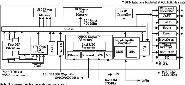
Figure 16-1: MSC8144 block diagram.
Each SC3400 core is a high-performance, general-purpose, fixed-point processor capable of 4 million multiply-accumulate operations per second (MMACS) for each MHz of clock frequency.
In addition to the SC3400 DSP cores, the MSC8144 includes the following memory system components:
• 16 Kbytes of Level 1 (L1) instruction cache and 32 Kbytes of Level 1 data cache per core offering zero-wait state access by each core
• 128 Kbytes of Level 2 (L2) instruction cache shared among the SC3400 cores
• 512 KBytes of SRAM M2 memory with four interleaved banks for up to four simultaneous 128-bit wide accesses at 400 MHz
• 10 MBytes of M3 memory implemented on a second die in a multi-chip-module (MCM) using embedded DRAM
The chip-level arbitration and switching system (CLASS) is an interconnect fabric that provides the system master devices with an access to slave resources, such as memory and device peripherals. The DMA controller on the MSC8144 enables data movement and rearrangement in parallel with the SC3400 core processing.
The MSC8144 is a true SMP device because all four SC3400 cores are identical processors and all four have access to the full memory subsystem in the device. This chapter uses the terms processor and core interchangeably.
Multcore programming models
Two general multicore processing models applicable to an SMP device such as the MSC144 are introduced in this section:
• Multiple-single-cores in which the cores in an SMP environment execute an application independent of each other
• True-multiple-cores in which the cores in an SMP environment cooperate in some fashion to accomplish the task
This chapter will focus on the three areas, listed in Table 16-1 below. These topics are important when designing an application using either of the multicore models presented here.
Table 16-1: Multicore considerations.
| Areas to Consider | Description |
| Scheduling | The scheduling methodology for an application allocates the resources in the multicore system, primarily by managing the processing of the cores to meet the timing and functional requirements of the application most effectively. |
| Inter-core communications | The interaction between cores in a multicore environment is largely used for passing messages between cores and for sharing common system resources such as peripherals, buffers, and queues. In general, the OS includes services for message passing and resource sharing. |
| Input and output | The management of input and output data. Defines the partitioning and allocation of input data among the cores for processing and the gathering of output data after processing for transfer out of the device. |
In addition to the items listed in Table 16-1, there are other important areas of consideration when porting applications to a multicore environment that are not addressed by this chapter.
The following sections describe two programming models for a multicore device along with a discussion of some of the points that typically create challenges when implementing applications using these concepts.
Multiple-single-cores
In a multiple-single-cores software model, all cores in the system execute their application independently of each other. The applications running on each core can be identical or different.
This model is the simplest way to port an application to a multicore environment, because the individual processors are not required to interact. Thus, porting basically involves replicating the single-core application on each of the corresponding cores on the multicore system. Thus, the developer basically replicates the single-core application on each of the cores in the multicore system such that their processing does not interfere with each other.
Figure 16-2 shows a multiple single core system. This example uses a Media Gateway for a voice over IP (VoIP) system on the MSC8144 DSP. Each core executes independently from the other cores in the DSP using data streams corresponding to distinct user channels. QUICC Engine™ is a network subsystem that is used to perform parsing, classification, and distribution for incoming network traffic.
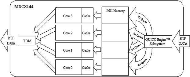
Figure 16-2: Multiple-single-core system example.
Advantages of multiple-single-cores
One broad benefit of the multiple-single-cores model is that scaling the system by the addition of cores to the system, or by increasing the functional complexity of the application executing on each core can be as straightforward as making the same change on a single-core system, assuming other system constraints such as bus throughput, memory, and I/O can support the increased demand.
There are other worthwhile advantages of using this model for an application, as indicated in Table 16-2.
Table 16-2: Advantages of multiple-single-cores.
| Areas to Consider | Advantage |
| Scheduling | The lack of intentional interaction between cores precludes the need for task scheduling and load balancing between cores. Consequently, the associated complexity and overhead is eliminated which results in a more predictable system that is easier to maintain and debug. |
| Inter-core communications | Independent core operation eliminates the need for inter-core communication and its resulting overhead. This also minimizes data coherency issues between cores. |
| Input and output | The cores are not involved in partitioning or distributing the input or output data. Although the input data for a device may arrive through a single peripheral device or DMA controller, the data is partitioned into independent ‘streams’ for each core by the hardware peripheral. Thus no software intervention by the core is required to determine which portion of the incoming data belongs to it. The same applies to output data. It can be reassembled into a single output stream by the peripheral hardware from the independent data streams coming from each core, and then be transmitted over the appropriate output port(s). |
Disadvantages of multiple-single-cores
The multiple-single-core model has inherent drawbacks, as listed in Table 16-3.
Table 16-3: Disadvantages of multiple-single-cores.
| Areas to Consider | Disadvantage |
| Scheduling | Applications using the model may have cases in which some cores are overloaded while others are minimally loaded or even idle. This occurs simply because the system does not have a way of scheduling the processing tasks among the cores; each core must process the data assigned to it. |
| Inter-core communications | Inability to communicate or dynamically assign tasks between cores. |
| Input and output | The I/O peripherals must be capable of partitioning the data into independent streams for each core. In the example shown in Figure 16-2, the MSC8144 QUICC Engine subsystem supports the multiple I/O ports necessary to interface to the IP network. In addition, the operating system or framework used to execute the application must provide adequate services to manage the I/O devices. |
Characteristics of multiple-single-cores applications
The following list describes the general characteristics of an application suitable for the multiple-single-cores model:
• A single core in the multicore system is capable of meeting the requirements of the application using the corresponding portion of the system resources associated with that core (memory, bus bandwidth, IO, and so forth).
• The I/O for the application must be assignable to each core with no runtime intervention. The assignment of data to a core occurs at compile time, at system-startup, or by an entity outside the multicore device.
• The multiple-single-core model supports more predicable execution because the application executes on a single core without any dependence on or interaction with other cores. Thus, applications that have a complicated control path or very strict real-time constraints are better suited to a multiple-single-cores implementation.
• The application has a data processing path consisting of tasks or functional modules that efficiently use the caches on the device. An application that has processing modules that do not use cache efficiently may require partitioning among multiple cores so the caches do not thrash.
True-multiple-cores
In the true-multiple-cores model, the cores in a multicore environment cooperate with each other and thus better utilize the system resources available for the application. For some applications, the true multiple cores is the only option because the application is too complex or large to process using the multiple single core model.
In a true-multiple-core system the cores do not generally perform identical tasks because the processing is partitioned among the cores, either at the application level, the scheduling, the I/O or in some other manner. The example in Figure 16-3 shows an application in which Core 0 and Core 1 each perform different portions of the application processing. The input stream is used by Core 0 and the output data is generated by Core 1. Intermediate results are passed between Core 0 and Core 1.
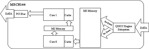
Figure 16-3: “True” multiple-cores model example.
Advantages of true-multiple-cores
Table 16-4 lists the advantages of using the true-multiple-cores model in achieving design goals.
Table 16-4: Advantages of true-multiple-cores.
| Areas to Consider | Advantage |
| Scheduling | The scheduler for true-multiple-cores has the ability to dynamically manage the system resources as a whole. This scheduling can be implemented in different ways. The scheduling intelligence can be centralized in a single core which assigns tasks to the remaining cores in the system, or distributed among multiple cores in the system with each core deciding which tasks to perform. In either situation, the system resources are better utilized and thus the performance of the application is maximized. |
| Inter-core communications | The nature of this communication is application specific and generally involves the passing of control and status information between the cores. The messages can be to a specific core or broadcast to all the cores. In general, the OS provides the necessary mechanisms for the inter-core communications through an API. The communication between cores allows the cores to cooperate with each other. |
| Input and output | In true-multiple-cores, it is possible to have a centralized entity, such as a core, manage the I/O for the application. This has an advantage that it can reduce the overall overhead associated with managing the I/O. |
Disadvantages of true-multiple-cores
Use of the true-multiple-cores model is limited by a point of diminishing returns beyond which the application complexity simply requires too much overhead or renders the system less than deterministic. The complexity is largely due to the required scheduling, inter-core communication, and I/O activities, all of which impose overhead onto the basic application processing. Table 16-5 summarizes the details associated with each of these areas.
Table 16-5: Disadvantages of true-multiple-cores.
| Areas to Consider | Disadvantage |
| Scheduling | The by the scheduler incurs overhead in the system, which can adversely affect the real-time requirements of the application. This must be offset by the increase in performance obtained from the cores cooperating with each other. |
| Inter-core communications | The overhead due to messages going between the cores can also negatively affect the performance of the application. Furthermore, the dependencies between tasks executing in different cores will also affect the performance of the system as a whole. |
Porting guidelines
This section provides guidelines for porting a single-core application to a true-multiple-core model with a master-slave approach. The motion JPEG example presented illustrates the principles presented.
Design considerations
The first major activity in porting an application from a single to a multicore environment is to identify the threads or tasks that can execute concurrently by the multiple cores. Use the following general guidelines when determining and evaluating these tasks:
• Choose tasks with real-time characteristics.
• The tasks in a multicore environment should have clearly defined real-time characteristics just as they do in a single core application.
• Avoid tasks that are too short.
• The overhead associated with short tasks is proportionally more significant than for larger tasks. Over-partitioning an application with the aim of providing flexibility and concurrency will generally create a large number of tasks and priorities spread out over several cores complicating the scheduler, increasing overhead, and making it harder to implement and debug.
• Minimize the dependencies between cores. Over-designing the tasks and their interaction complicates the application and makes the system more difficult to implement and debug. Inter-core dependencies also incur an overhead.
• Task execution in a single core device forces tasks to execute sequentially. In a multicore environment, the same tasks can execute concurrently and tasks do not necessarily complete in the same order as in a single core. A multicore environment can expose dependencies that are hidden in a single core environment.
Note
Consider a simple application with three tasks A, B, and C that execute at the same priority. Task C can execute only after task A and B have completed. In a single core environment the application can be written such that task A triggers B which then triggers C. In a multicore device, task A and B can execute simultaneously on separate cores, so task C must now wait for both tasks A and B to begin execution, not just task B as in the single core environment. Though this is a simple example, consider a more realistic situation in which several cores execute many prioritized tasks whose execution time may change at runtime due to dependencies on the data being processed.
Motion JPEG case study
This case study demonstrates how a motion JPEG application is ported to the MSC8144 DSP using the true multiple cores model. This application was selected because it illustrates most of the major discussion points for this application note. The input data stream consists of a real-time sequence of raw video images (frames) that arrive over the DSP network connection. The DSP cores all cooperate in the processing of the video stream by encoding a portion of the current frame using the JPEG compression algorithm. The output data stream is then reassembled into the same order in which it was received and it is sent back over the network connection in this encoded format to a personal computer (PC) where it is decoded (uncompressed) and displayed real-time.
JPEG encoding
The JPEG encoding process consists of the five steps shown in Figure 16-4. The decoding process consists of the same steps inversed and performed in the reverse order.
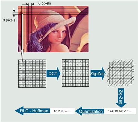
Figure 16-4: The JPEG encoding process.
Input data
The input video stream consists of continuous raw digital images partitioned into blocks of pixels called Minimum Coded Units (MCUs). An MCU consists of a 16 × 16 array of 8-bit pixels composed of 256 bytes of luminance information (Y) and 256 bytes of chrominance (Cb and Cr) information. Luminance is provided for every pixel in the image and chrominance is provided as a medium value for a 2 × 2 block of pixels.
The 512-byte MCU is partitioned into four 8 × 8 pixels blocks that serve as inputs to the Discrete Cosine Transfer processing block. There is no relation between any two MCU blocks.
Discrete cosine transfer
The purpose of the discrete cosine transfer (DCT) is to convert the information in the original raw pixels blocks into a spatial frequency representation of the block. These spatial frequencies represent the level of detail in the image. Thus, a block with a lot of detail in it has many high spatial frequency components while blocks with low detail are represented by a majority of low frequency components. Typically, most of the information is concentrated in a few low-frequency components.
The DCT is applied to an 8 × 8 block of pixels from left to right and from top to bottom of an image frame. The result is a new 8 × 8 block of integers (called DCT coefficients) that are then reordered using a zig-zag pattern.
Zig-zag reordering
The 8 × 8 block of DCT coefficients is traversed using a zig-zag pattern as shown in Figure 16-5.

Figure 16-5: Zig-zag pattern used to traverse DCT coefficients.
The result of this reordering is a vector of 64 elements (0 to 63) arranged from lowest to highest frequency components. The first value in the vector (0) is called the DC component and represents the lowest frequency component. The other coefficients in the vector (1 to 63) are called the AC coefficients. The 64-item vector is then passed to the quantization block for processing.
Quantization
In this step, each value in the 64-coefficient vector resulting from the zig-zag reordering step is divided by a predefined value and rounded to the nearest integer. The quantization step removes the high frequency components (greater detail) of the input vector because the human eye is more sensitive to lower frequency components than higher frequency components. This is done by dividing the higher frequency coefficients in the vector by larger values than those used to divide the lower frequencies. This action forces the higher frequency components to have more zeros.
Run-length coding
This run-length coding (RLC) exploits the fact that we have consecutive zeros for the higher frequency components of the input vector by providing a pair of integers indicating the number of consecutive zeros in a run followed by the value of the non-zero number following the zeros. For example, consider the run of coefficients: 45, 33, 0, 0, 0, 12, 0, 0, 0, 0, 0, 0, 0, 0, 5. The zero run-length code becomes (0,45), (0,33), (3,12), (7,5). There are special situations that are not addressed here.
Huffman coding
This process uses a variable-length code table to map the right integer in each numbered pair generated in the previous coding step with another bit string that uses minimal space to represent the original information. This is advantageous because the variable-length code table is carefully designed to represent the most common input data patterns with shorter bit strings than for the less common input values. The result is a string of bits that is smaller in size than the original input data.
Design considerations
The overall requirements for processing the JPEG algorithm require only a small portion of the MSC8144 processing capabilities. Therefore, several JPEG encoder tasks can execute on each core on multiple input video data streams. This section discusses several characteristics of the motion JPEG (MJPEG) application and how these influenced the decisions made in the process of porting to the multicore MSC8144 DSP.
Input
The input data stream for a motion JPEG (MJPEG) encoder consists of a contiguous flow of raw digital images (frames). The frames are sent to the DSP at a particular frame rate determined on the PC. When a frame is sent to the DSP, the frame is partitioned into blocks of MCUs and then transmitted to an IP address defined on the network interface of the DSP. The rate at which the MCU blocks are transmitted to the DSP is predetermined and does not change regardless of the video frame rate.
For this application, it is sufficient (and simpler) for a single core to manage the QUICC Engine™ subsystem and service the resulting interrupts and then partition the input data block for processing by the other cores.
Scheduling
This is a soft real-time application because there are no hard real-time constraints. There are no imposed output frame rates at which the application must transmit the output video stream; the PC simply stalls the display of the video stream received from the DSP if the output frame rate slows below the expected rate (or stops all together).
Similarly, latency is of no consequence for this application because the DSPs do not have a fixed amount of time to complete the processing. However, we will require the DSP to process the incoming data blocks as they arrive over the network interface.
Because the MCU blocks in a frame are independent, there are no restrictions on which core processes a given block. Furthermore, it is best not to assign the incoming blocks to a specific core statically, because the performance of some of the tasks in the JPEG algorithm depends on the data being processed. Thus, the cores on the DSP are better utilized by dynamically allocating the data blocks to the cores based on the processing load of the core.
These characteristics, in conjunction with the input considerations discussed in Input, make the application a good candidate for the true multiple cores model using the master-and-slave approach to scheduling. The master core manages the incoming data stream and assigns tasks to the available cores, including itself, based on the available processing cycles.
Inter-core communication
The master core copies a pointer to the memory location of the next MCU data block to process into a global queue that is accessible by all the cores and then notifies the slave cores that there is data available for processing.
All non-idle cores, including the master core, then compete to process the input block. If a core is already processing a block, it ignores the message from the master core.
Output
The output video stream is sent over the network to a PC for decoding and display in real-time. Due to the data-dependent nature of the application JPEG algorithm, the encoded data blocks resulting from the core processing can potentially not be available in the same order as the input data blocks. This is an example of a hidden dependency on the flow order that would not exist if the application was executing on a single processor. Thus, the output data blocks must be placed in order before transmitting back to the PC. This process is called ‘output serialization’ and is assigned to the master core. The master core must pause the output data stream from the device until the next data block in the sequence is available.
Implementation details
One implementation of a true-multiple-cores model is referred as master-slave. In a master-and-slaves implementation, the control intelligence for the application resides in a master core. The other cores in the system become slave cores. The master core is responsible for scheduling the application processing and possibly managing the I/O. Figure 16-6 shows a system in which Core 0 is assigned the role of master core. Core 0 manages the I/O for the application and assigns tasks to the slave cores 1, 2, and 3 via a task queue in memory.
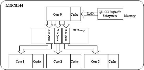
Figure 16-6: Master and slaves systems.
The remainder of the chapter focuses on a master-slave approach to a true-multiple-cores application.
The development tools for the MSC8144 used in the development process included the following:
• CodeWarrior® Development Studio.
The development studio is a complete integrated development environment (IDE) that contains all of the tools needed to complete a major embedded development project, from hardware bring-up through programming and debugging embedded applications.
Two useful features used from the CodeWarrior IDE were the Kernel Awareness plug-in module for visualization and debugging of the SmartDSP Operating System (SDOS) and a Profiler that allowed evaluation of the performance of various modules and interactions in the system.
• SmartDSP Operating System (SDOS).
SDOS is a preemptable, real-time, priority-based operating system, specially designed for high-performance DSPs operating with tight memory requirements in an embedded environment. It includes support for multicore operations such as synchronization modules and inter-core messages to manage inter-core dependencies. A convenient and unified application program interface (API) supports various types of peripheral I/O devices and DMA controllers.
The steps we used to port the MJPEG application followed a straightforward approach as follows. First we ran a single instance of the MJPEG application on a single core of the MSC8144. Once this functionality was properly validated, we ran two or more instances of the MJPEG processing on the same core. This was helpful because the debugging process is simpler on one core than on multiple cores. During this process, we were also able to use the MSC8144 functional simulator available with the CodeWarrior IDE, eliminating the need for the actual hardware for this portion of the development. After these initial steps, the MJPEG application was executed on more than one core without any inter-core communication. Lastly, we added the inter-core functionality.
Scheduling
In the master-and-slaves scheduling implemented on the MSC8144 for this application, the main scheduler functionality resides in core 0, the master core. Cores 1, 2, and 3 in the system become slave cores. The master core manages the I/O and processing for the application and the slave cores wait for tasks to be processed as shown in Figure 16-7.
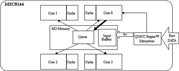
Figure 16-7: Task scheduling.
Figure 16-7 shows that the incoming raw video images are received in blocks by the MSC8144 QUICC Engine network interface. The master core services the QUICC Engine interrupt and then sends a message to the slave cores with the information pertinent to the received block. The slave cores are notified by messages placed in this queue which then vie to access the message and be assigned the task of JPEG encoding the video data block. If a slave core is already processing a block, it de-queues a task until it completes the encoding of the current data block.
Note
Core 0, even though it is the master core, is also notified when messages are posted to the task queue and can perform the JPEG encoding of a block if it has available processing bandwidth.
Once a slave core finishes the JPEG encoding process, it notifies the master core via another message queue as shown in Figure 16-8. The master core de-queues the information for each encoded block and determines whether it is the next output block in the output stream (a process called serialization). If that is the case, the master core transmits the encoded block to the network using the QUICC Engine interface.
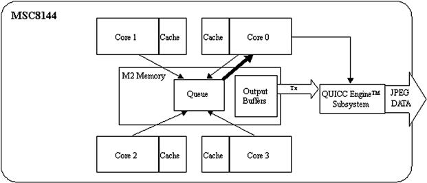
Figure 16-8: Task completion.
It also transmits any additional encoded blocks that are available in the serialized sequence.
If the master core performed the encoding task, it does not use the queue process, and it simply serializes the output and transmits the buffer (if possible).
The SDOS operating system provides the basic building blocks for the scheduling of the application. In other words, the master core implements the scheduling methodology by making calls to SDOS services through the operating system API. Similarly, the slaves respond to the master core using SDOS services.
The background task in SDOS is a user-defined function that executes when no other task in the application is required to execute. This task has the lowest priority and executes indefinitely in a loop until a higher priority task is enabled. The background task for this application places the corresponding core in the WAIT state by executing the wait instruction. The WAIT state is an intermediate power-saving mode used to minimize core utilization and reduce power consumption. In this case, the cores each remain in the WAIT state until a message arrives indicating a block of pixels is available for JPEG encoding, or, if it is the master core, an encoded block is ready to transmit.
Inter-core communication
The inter-core communication for the application consists primarily of the messages exchanged between the master core and the slave cores. These messages are implemented in this application using services provided by SDOS accessed through calls to the operating system API. The flow of inter-core communication for the application is shown in Figure 16-9.
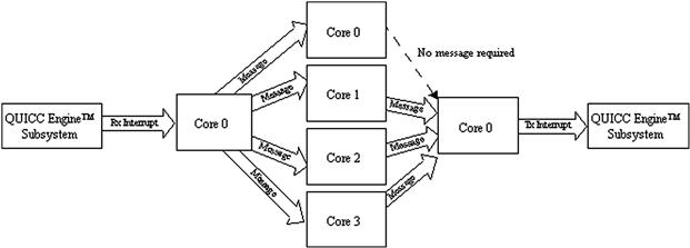
Figure 16-9: Inter-core communication flow diagram.
The QUICC Engine subsystem interrupts the master core after several blocks of the raw video image are received. In the receive interrupt service routine (ISR), core 0 sends messages to all the slave cores and to itself to indicate there is data ready for JPEG encoding. After the encoding process, the slave cores send a message back to the master core indicating there are blocks of encoded data ready to transmit. Core 0 does not need to send a message to itself.
During the initialization process, each core creates queues used to send and receive messages as indicated in Table 16-6. The messages have two purposes. Messages from the master core (core 0) indicate that a block of raw video data was received and is available to encode. Messages from the slave cores (cores 1 through 3) indicate that a block has been encoded and is ready to transmit. A block encoded by core 0 is serialized for transmission with no message generation.
Table 16-6: Message queues defined during initialization.
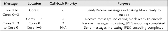
Messages are implemented using MSC8144 virtual interrupts between the cores. Priorities associated with the user function called when a message is received by a core are indicated in Table 16-6.
Input and output
The I/O for the motion JPEG application also requires special consideration. The input of the raw video data arrives at the MSC8144 QUICC Engine interface from a PC over an IP network connection. As mentioned previously, the master core (core 0) initializes and services the interrupts for the QUICC Engine subsystem. Incoming data blocks are not copied. Instead, control information is passed to the slave cores in a message with a pointer, size, and other information needed to locate the data and complete the JPEG encoding processing.
The data output process is more involved. The output blocks must be sent back to the PC over the IP network in the same order in which they were received, but since the JPEG encoding processing is data dependent, the cores can complete the encoding process for a block out-of-order, which means the output blocks become available out of order. Thus, the output blocks must be buffered and placed back in order, a process called output serialization.
The master core executes the serialization by collecting pointers to the output buffers as they are made available by the slave cores. Encoded buffers are then transmitted to the PC only when the next blocks in the sequential output data stream are available. This process is depicted in Figure 16-10. In this example, the serializer shows that output blocks #6, #7, and #9 are available to be sent to the PC; however, the next block the PC is expecting is block #5 as indicated to by the Current pointer. Slave core 1 finishes encoding output block #10 and notifies the master core which then adds it to the serializer accordingly. Core 0 then provides output block #5 which then allows blocks #5 through #7 to be sent to the PC, after which the serializer must wait for block #8 in the sequence.
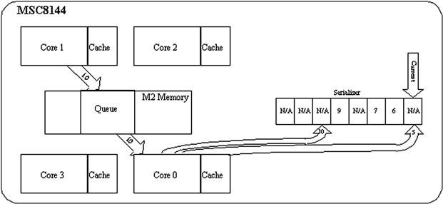
Figure 16-10: Output serialization.
The serializer concept is similar to the jitter buffer used in voice over IP (VoIP) applications. The differences are that the jitter buffer in VoIP is located at the receiving end of the voice connection.
Conclusions
Designers of multicore applications must consider several factors including processing and task properties, hardware characteristics such as the cache and peripheral support, and the multicore support provided by the OS and tools. For example, the Kernel Awareness module of the CodeWarrior Development Studio proved invaluable in the implementation and debugging of the motion JPEG application.
Because a multicore system also exposes hidden dependencies and complexities, it is always a good idea to start with a simple scenario or subset of the application processing, and then improve form there. For example, it is generally impractical to try to obtain optimal task scheduling, inter-core communication, and I/O methodologies in the early development stages. It is better to begin with a single core using static scheduling and improve the design though testing and tuning.
To support effective application development in a multicore and multi-task environment, Freescale multi-processing offerings not only include multicore SMP devices such as the MSC8144 DSP, but also provide development environments like the CodeWarrior Development Studio, and hardware and software tool support that can help the designer develop application systems, measure their system performance and resource and processing utilization, and tune, test, and debug their functionality.