Chapter 9. The Camera and Optics
There is only you and your camera. The limitations in your photography are in yourself, for what we see is what we are.
—Ernst Haas
Visual effects might seem to be all about realism, but that’s not quite the goal; the compositor’s actual job is more precisely to simulate the real world as it appears through the lens of a camera. The distinction is critical, because the photographed world looks different from the one you see with the naked eye and consider to be reality.
An understanding of cinematography is essential to compositing, because After Effects offers the opportunity to re-create and even change essential shooting decisions long after the crew has struck the set and called it a wrap. Your shot may be perfectly realistic on its own merits, but it will only belong in the story if it works from a cinematic point of view. Factors in After Effects that contribute to good cinematography include
• field of view
• depth of focus
• the shooting medium and what it reveals about the story (or if you like, the storyteller)
• planar perspective and dimensional perspective
• camera motion (handheld, stabilized, or locked) and what it implies about point of view
These seemingly disparate points all involve understanding how the camera sees the world and how film and video record what the camera sees. All of them transcend mere aesthetics, influencing how the viewer perceives the story itself.
Cameras: Virtual and Real
Our exploration of virtual cinematography begins with the After Effects camera, which relates closely to an actual motion picture camera without actually being anything like one. You can exploit the similarities as well as strong differences between 3D in After Effects and real-world counterparts: the camera, lighting and shading options.
See with the Camera
Toggle a layer to 3D and voilà, its properties contain three axes instead of two—but enabling 3D without a camera is a little bit like taking a car with a fully automatic transmission into a road race: You’re fine until things get tricky, at which point you may hit the wall.
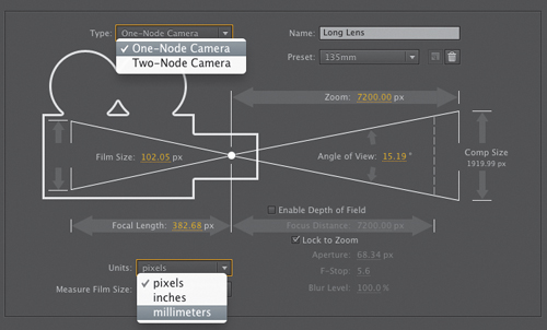
The Camera Settings dialog (Figure 9.1) includes a unique physical diagram to describe how settings in the 3D camera affect your scene.
Figure 9.1. The Camera Settings dialog provides a visual UI to elucidate the relationship between values. The 50 mm preset selected in the Preset menu is the neutral (default) setting; use it for neutral perspective.
Lens Settings
Although it is not labeled as such, and despite that After Effects defaults to any previous camera settings, the true neutral default After Effects lens is the 50 mm preset in Camera Settings. This setting (Figure 9.2) is neither wide (as with lower values, Figure 9.3) nor long (as with higher values, Figure 9.4), and it introduces no shift in perspective, in a scene that contains Z depth.
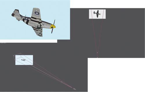
Figure 9.2. The default lens (50 mm setting). If settings are at the defaults, with Z Position value the exact inverse of the Zoom value, the resulting camera does not shift the comp’s appearance.
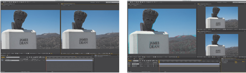
Figure 9.3. An extreme wide field of view does not distort in the “fish-eye” manner of a short glass lens, but it does radically alter the perspective and proportions of this 3D model imported into After Effects via Photoshop.
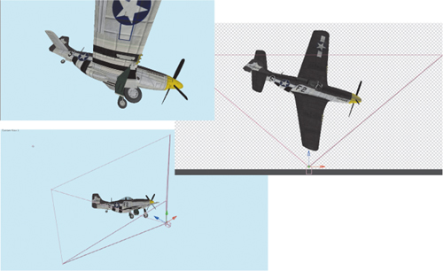
Figure 9.4. A narrow “telephoto” lens shortens the apparent length of the wings dramatically.
Notes
![]()
The folder 09_3d_lens_angles on the book’s disc contains the cameras and 3D model used for the figures in this section.
“50 mm” is literally meaningless, because virtual space doesn’t contain millimeters any more than it contains kilograms, parsecs, or bunny rabbits. This is the median lens length of a 35 mm SLR camera, the standard professional still image camera.
Motion picture cameras are not so standardized. The equivalent lens on a 35 mm film camera shooting Academy ratio itself has a 35 mm length. A miniDV camera, on the other hand, has a tiny neutral lens length of around 4 mm. The length corresponds directly to the size of the backplate or video pickup, the area where the image is projected inside the camera.
Lens length, then, is a somewhat arbitrary and made-up value in the virtual world of After Effects. The corresponding setting that applies universally is Angle of View, which can be calculated whether images were shot in IMAX or HDV or created in a 3D animation package.
Real Camera Settings
To understand the relationship of the After Effects camera to that of a real-world camera, look again at the Camera Settings diagram introduced in Figure 9.1. Four numerical fields—Film Size, Focal Length, Zoom, and Angle of View—surround a common hypotenuse.
Notes
![]()
A fifth numerical field in Camera Settings, Focus Distance, is enabled by checking Enable Depth of Field; it corresponds to a camera’s aperture setting.
A prime (or fixed) lens has static values for all four. A zoom lens allows Zoom and Focal Length to be adjusted, changing Angle of View. Either lens will resolve a different image depending on the size of the sensor (or film back, or in this case the Film Size setting). These four settings, then, are interrelated and interdependent, as the diagram implies. Lengthen the lens by increasing Focal Length and the Angle of View decreases proportionally.
Angle of View is the radius, in degrees, from one edge of the view to the other. If you have calculated this number in order to match it, note that Camera Settings lets you specify a horizontal, vertical, or diagonal measurement in the Measure Film Size menu.
In After Effects, the Zoom value is the distance of the camera, in pixels, from the plane of focus. Create a camera and its default Z Position value is the inverse of the Zoom value, perfectly framing the contents of the comp at their default Z Position, 0.0 (Figure 9.5). This makes for easy reference when measuring depth of field effects, and it lets you link camera position and zoom together via expressions (for depth of field and multiplane effects, discussed later).
Figure 9.5. The two exposed pulldown menus aren’t available in the Timeline panel itself. The default position of a new camera corresponds to the Zoom value, which can be viewed here in pixels. A One-Node Camera has no point of Interest, like a real-world camera.
Emulate a Real Camera
Other considerations when matching a real-world camera include much of the material that follows in this chapter, such as
• depth of field. This is among the most filmic and evocative additions to a scene. Like any computer graphics program, After Effects naturally has limitless depth of field, so you have to re-create the shallow depth of real-world optics to bring a filmic look to a comp.
• zoom or push. A move in or out is used for dramatic effect, but a zoom and a push communicate very different things about point of view.
• motion blur and shutter angle. These are composition (not camera) settings; introduced in Chapter 2 and further explored here.
• lens angle. The perspective and parallax of layers in 3D space change according to the angle of the lens used to view them.
• lens distortion. Real lenses introduce curvature to straight lines, which is most apparent with wide-angle or “fish-eye” lenses. An After Effects camera has no lens, hence, no distortion, but it can be created or removed (see the section “Lens Distortion”).
• exposure. Every viewer in After Effects includes an Exposure control (![]() ); this (along with the effect with the same name) is mathematically similar but different in practice from the aperture of a physical camera. Exposure and color range is detailed in Chapter 11.
); this (along with the effect with the same name) is mathematically similar but different in practice from the aperture of a physical camera. Exposure and color range is detailed in Chapter 11.
• boke, halation, flares. All sorts of interesting phenomena are generated by light when it interacts with the lens itself. The appeal of this purely optical phenomenon in a shot is subjective, yet it can offer a unique and beautiful aesthetic and lend realism to a scene shot under conditions where we would expect to see it (whether we know it or not).
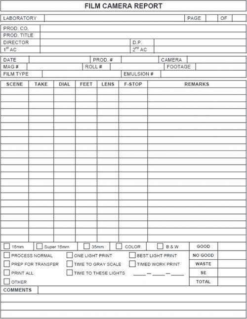
A camera report is a record of the settings used when the footage was taken, usually logged by the camera assistant (or equivalent).
The Camera Report
Maintaining an accurate camera report on a shoot (Figure 9.6) is the job of the second assistant camera operator (or 2nd AC). The report includes such vital information on a given scene and take as ASA and f-stop settings, as well as the lens used. Lens data is often vital to matching the scene with a virtual camera, although there are methods to derive it after the fact with reasonable accuracy. A great tip for a VFX supervisor is to take a shot of the camera itself on a given VFX shot so that there is visible reference of the lens and focal settings, in case they aren’t recorded accurately.
Figure 9.6. This page from The Camera Assistant’s Manual by David Elkins, SOC, shows the type of information typically recorded on a camera report, including lens and f-stop data for a given scene and take. The criteria are somewhat different when shooting digitally but fundamentally similar.
The basic job of the visual effects supervisor is to record as much visual reference data as possible (typically using a DSLR camera) in addition to maintaining clear communications with the cinematographer, with whom the VFX supervisor is mutually dependent.
Notes
![]()
If lens data is missing for a given plate, it is possible to derive it if the vanishing point and a couple of basic assumptions about scale can be determined. Check the book’s disc for a demonstration of how to do this courtesy of fxphd.com.
There are several other bits of data that can be of vital interest in postproduction, and these go beyond what is recorded in an ordinary camera report. Focal distance (a measurement from camera to subject), camera height, any angle to the camera if it is not level, and any start and end data on zooms or focus pulls might be missing from the standard camera report. When supervising, be sure to ask that these be included, particularly if any 3D tracking will be necessary.
With accurate information on the type of camera and the focal length of a shot, you know enough to match the lens of that camera with an After Effects camera.
Tip

An alternative to the listed steps, for those who like using expressions, is to use the following expression on the camera’s Zoom property:
FocalLength = 35 //
change to your value,
in mmhFilmPlane = 24.892 //
change to film size, in
mm (horizontal); mul-
tiply values in inchesby 25.4
this_comp.width*(Focal
Length/hFilmPlane)
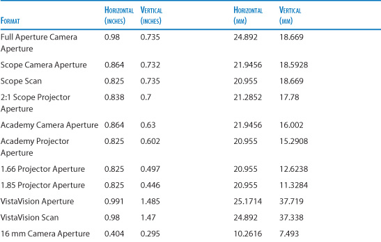
Table 9.1 on the next page details the sizes of some typical film formats. If your particular brand and make of camera is on the list, and you know the focal length, use these to match the camera via Camera Settings (double-click the camera layer to reveal). The steps are as follows:
- Set Measure Film Size to Horizontally. (Note that hFilmPlane in the expression stands for “Horizontal Film Plane.”)
- Set Units to millimeters.
- Enter the number from the Horizontal column of the chart that corresponds to the source film format.
- Enter the desired Focal Length.
Table 9.1. Typical Film Format Sizes
Once the Angle of View matches the footage, tracked objects maintain position in the scene as the shot progresses. It’s vital to get this right when re-creating a camera move, especially if a particularly wide or long lens was used, or things simply may not line up correctly. It’s even more important for camera projection (discussed later).
Lens Distortion
A virtual camera with a wide-angle view (like the one back in Figure 9.2) has a dramatically altered 3D perspective but no actual lens. A virtual camera is only capable of gathering an image linearly—in a straight line to each object.
A physical lens curves light in order to frame an image on the flat back plate of the camera. The more curved the lens, the wider the angle of view it is able to gather and bend so that it is perpendicular to the back of the camera. A fish-eye view requires a convex lens a short distance from the plate or sensor in order to gather the full range of view.
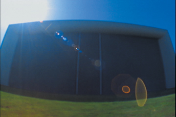
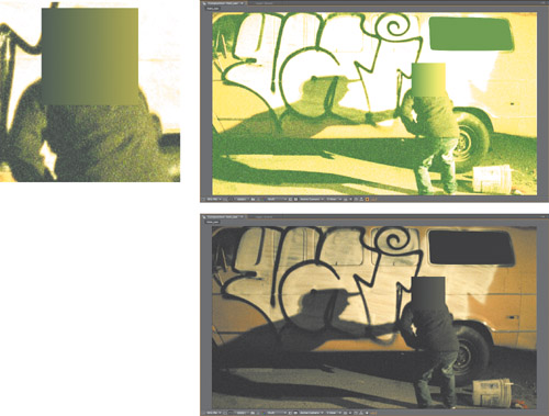
At the extremes, this causes easily visible lens distortion; items in the scene known to contain straight lines don’t appear straight at all but bent in a curve (Figure 9.7). The barrel distortion of a fish-eye lens shot makes it appear as if the screen has been inflated like a balloon.
Figure 9.7. The nearly psychedelic look of extreme lens distortion; the lens flare itself is extremely aberrated. You can create just as wide a lens with the 3D camera, but there would be no lens distortion because there is no lens.
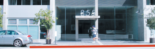
As you refine your eye, you may notice that many shots that aren’t as extreme as a fish-eye perspective contain a degree of lens distortion. Or you might find that motion tracks match on one side of the frame but slip on the opposite side, proportions go out of whack, or things just don’t quite line up as they should (Figure 9.8).
Figure 9.8. The shot calls for the curb to be red, but a rectangular layer does not line up. Lens distortion is present in this shot.
The Optics Compensation effect is designed to mimic lens distortion. Increasing Field of View makes the affected layer more fish-eyed in appearance; the solution in this case is to apply that effect to the red rectangle layer. You can even remove fish-eye distortion (aka barrel distortion) by checking Reverse Lens Distortion and raising the Field of View (FOV) value, but the result is unnatural and the quantized pixels less aesthetically pleasing.
The setting is derived by eye, as follows.
- Having identified lens distortion (Figure 9.8), create a new solid layer called Grid. If you like, make it 10% to 20% larger than the source comp so that even when distorted, it reaches the edges of frame.
- Apply the Grid effect to the Grid layer. For a grid like the one in Figure 9.9, set Size From Width & Height and make the Width and Height settings equal, then give the grid the color of your choice (Figure 9.9).
Figure 9.9. The grid doesn’t line up with the largely rectilinear background near the bottom and top of frame.
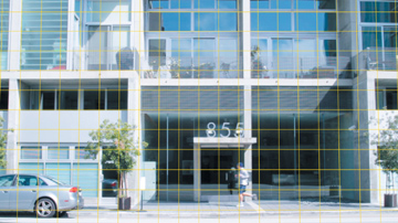
- Apply Optics Compensation and raise the FOV value until the grid lines up with the background. If necessary, rotate either the grid or the background image so that they are horizontally level with one another.
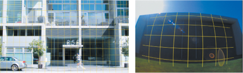
- Note that the vertical lines don’t match up, because the camera was tilted up when the shot was taken. Correct for this by making the Grid layer 3D and adjusting the X Orientation value (or X Rotation—these are interchangeable). Figure 9.10 shows a matched grid.
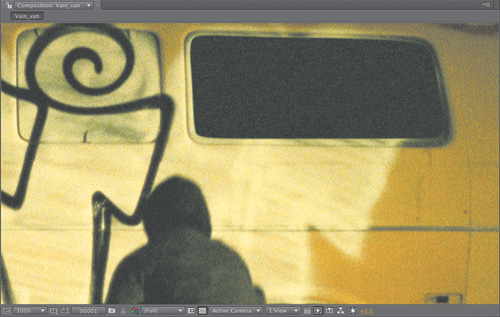
Figure 9.10. Optics compensation is applied to the grid, which is also rotated in 3D to account for camera tilt (left). Even the crazy shot from Figure 9.7 can be matched with the proper Optics Compensation setting.
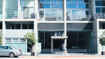
- Copy Optics Compensation (and, if necessary, 3D rotation) settings to the foreground curb element and switch its blending mode to Color. It now conforms to the curb (Figure 9.11).
Figure 9.11. The composited layer is distorted to match the curvature of the original background.
There’s one unusual detail in this particular shot—study the distorted grid over the curb and notice that the curb curves away from it, and from the white lines out in the street. The curb has a curve of its own in z space, which we know for certain because we’ve corrected the lens distortion. You can freely edit the object for such details if necessary without compounding the problem by fighting lens distortion.
3D
At this writing 3D display technology is all the rage, thanks to box office records for Avatar and higher ticket prices for the privilege of wearing silly glasses in the movie theater. Up to this point in the chapter we’ve seen how accurate re-creation of 3D is useful throughout the compositing process even when not working in stereo.
There’s an important distinction to be made between 3D input/output and the use of 3D in compositing. If you find yourself working with two simultaneous side-by-side images created for 3D stereo output, you’ll find that After Effects doesn’t offer much in the way of dedicated stereo tools. But even with 2D background footage being comped 2D, After Effects lets you freely mix 3D into your compositing process, as follows:
• A 2D background layer remains in place no matter what happens with the camera and 3D layers, which is key to 3D matchmoving to a 2D source clip.
• Standard 2D adjustment layers affect all layers below them, including 3D layers.
• 3D layers use standard blending modes (over 2D elements, they obey layer order, and with other 3D elements, Z-space depth).
But proceed with caution:
• When working with a track matte, the visible layer or the matte layer may be 3D, but in almost no case is it the right idea to make them both 3D with unique positions unless attempting to do something very strange.
• Paradoxically, plug-ins that work with After Effects 3D space typically reside on 2D layers (Figure 9.12).
Figure 9.12. Particles generated by Trapcode Particular fill the volume of 3D space, as is evident in a perspective view, although the effect is applied to a 2D layer.
• Precomp a set of 3D layers and it’s as if you have a single 2D view of them until you enable Collapse Transformations, at which point it’s as if the layers are back in the main composition. Almost as if, that is—light and camera layers are not passed through, and strange things can happen as you mix 2D layers, effects, and 3D precomps.
If you come up against a setup that isn’t working and doesn’t make sense, be a little scientific and carefully test removing one variable at a time, then undoing, until you find the one that is confusing things.
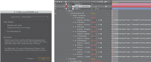
Photoshop 3D Models
The views of the plane that appear in Figures 9.2 through 9.4 were indeed rendered in After Effects. Unlike ordinary 3D layers, also known as “postcards in space,” this is a full 3D mesh with geometry, shading, and textures. Photoshop provides the means to open 3D models in specific formats—this one came in as an .obj with a few texture images—and save them as Photoshop .psd files. These files can then be imported into After Effects.
But is it worth the trouble? 3D models in After Effects tend to behave sluggishly (a high-end professional graphics card certainly helps) and have the following fundamental limitations:
• Textures, lighting, even anti-aliasing can be adjusted only in Photoshop.
• To adjust such Photoshop-only features, use Edit Original (Ctrl+E/Cmd+E), make the changes in Photoshop, then save and they appear in After Effects. It’s not what you’d call “interactive.”
• After Effects lighting, material options, and motion blur have no effect on Photoshop 3D layers, and there’s no easy way to articulate or otherwise work with the individual components of a complex model. Forget about spinning the propeller of that aircraft for some natural motion blur.
Figure 9.13 shows the basic Photoshop 3D setup in After Effects. The source Photoshop file has a single layer, but the comp generated upon import into After Effects contains three: a camera, a Controller layer, and the 3D image itself. You can replace or even eliminate the camera layer, but the other two must remain together or the layer becomes ordinary again, like Cinderella after midnight.
Figure 9.13. The Photoshop Import dialog accommodates Photoshop 3D layers; just check the Live Photoshop 3D box. The resulting comp (right) contains a camera, the image, and a controller layer; the image has a Live Photoshop 3D effect applied to it, which links it to the Controller via a set of expressions (in red).
To transform the 3D object, you work with the controller layer, a null. You can apply any standard image effects to the layer that contains the image itself. More fundamental changes to the appearance of the model are no more available than they would be in third-party software such as Maya, which can also render a much nice-looking image using modern lighting and shading techniques available in Mental Ray or Pixar Renderman.
If the lack of motion blur is the main thing standing in your way of using Photoshop 3D elements in After Effects, you can try adding an adjustment layer at the top of the comp containing your 3D animation. Next:
• Apply the Timewarp effect to that layer. Change speed to 100 and toggle Enable Motion Blur, then set the other Motion Blur settings to get the look you want.
• Apply CC TimeBlend for a less render-intensive approach that won’t work with heavy motion (and is frankly a bit eccentric to preview—if it looks strange, try hitting the Clear button at the top of the effect and regenerating the preview).
These are the same workarounds you would use if for some reason your 3D render had no motion blur; it’s a less accurate and, especially in the case of Timewarp, more render-intensive approach. More about using Timewarp to generate motion blur can be found in Chapter 2.
Close-up: DigiEffects FreeForm AE for 3D Displacement and Warps
![]()
After Effects CS5 adds a plug-in which at long last can bend any layer into true 3D space instead of limiting image data to the “postcards in space” model. Many plug-ins including Particular and 3D Stroke operate in true 3D and interact with the After Effects camera. Only DE_FreeFormAE, however, can take an existing image and either warp it, via a mesh, or displace it, using a bitmap, into 3D space (so that as the camera moves around it, the shape is revealed to be three-dimensional).
You can use this plug-in to match objects in a scene—for example, replacing the label on a can that the camera moves around by bending it with a mesh—or to displace your own custom geometry (a staircase uses a row of gray bars, while more natural mountain or water topography can be re-created with a fractal noise map). To re-create the motion of a flag in 3D, you might both ripple it with a displacement map and create the broader flapping motion by keyframing a mesh animation. Tutorials showing how to use it are available at www.digieffects.com.
Stereo Output
With Nuke, the Foundry has led stereo compositing with dedicated tools such as Ocula to smooth the process. After Effects leaves you largely on your own to figure out how to work on two image channels simultaneously in order to change them. Not that much has changed in After Effects regarding 3D comping since the days when we comped movies such as Spy Kids 3D at the Orphanage, back when stereo display was considered kind of retro.
The big problem comping in stereo is twofold. First, you can only preview the resulting 3D image when you put on your 3D glasses and look at a final image, which is to say, when you stop working. The more difficult problem is that tiny incremental refinements that have any spatial component whatsoever have to be implemented the same, yet differently, on both channels. Roto is hard enough, but when the same element has to be rotoscoped identically on two channels that don’t match, you have a dilemma. And quite possibly, a headache.
You can keep two comp viewers side by side—or perhaps more conveniently for the rest of the UI, top and bottom. Generally you make all of your edits to one or the other channel (usually based on which one is destined to be the “hero” channel that will be displayed in 2D-only playback of the movie). In an ideal world you could get one channel perfect, then duplicate that comp, swap in the other channel, and make the necessary adjustments in one pass.
Unfortunately I never seem to spot any job listings from this “ideal world.” No matter how hard you try to get one layer to final before starting on the other one, there will be changes, and these must of course be consistent on both layers, with spatial offsets. And unless you set it up carefully and pay close attention, that turns into a game of whack-a-mole—only less fun.
The only procedural solution is to link as many elements together between left and right as possible. The biggest recent feature addition that would have helped me comp 3D features in After Effects a few years ago is the ability to link masks together with expressions; you simply apply an expression to a mask shape and then pick whip to the mask whose shape you want it to inherit. True, there’s no easy way to offset it automatically, but you can turn any expression into keyframes using Animation > Keyframe Assistant > Convert Expression to Keyframes and then offset the whole set or individual vertices using the Key Tweak script introduced in Chapter 7.
Script
![]()
Duplink, Jeff Almasol’s script introduced earlier, which is exclusive to this book and can be found on the disc (rd_Duplink.jsx), creates an instance layer whose properties are all linked to the original, allowing you to freely work in one channel and see updates in the other. You still have to set it up for each layer and effect you add, but it can certainly save tedious manual labor.
Convergence and 3D Previews
Previewing 3D in After Effects is most possible in anaglyph view (typically with red and blue glasses). Anaglyph does horrendous things to color and contrast, as each primary becomes effectively invisible in the corresponding eye. But prepping the channels for this type of display is simple with the Shift Channels effect. First create a render comp containing only the left and right channel composites. Now just turn off one channel in one eye, turn off the other two channels in the other eye, and set whichever layer is higher in the stack to Add mode to combine the two.
The other item necessary in this render comp is an interocular control, a fancy name for the distance between the two views. The proper way to set this is to match the average distance between human eyes, which is approximately 2.5 inches. Move the left and right channels further or closer horizontally and the apparent depth (and convergence point, if any) changes, more or less respectively. You can rig a simple expression to a Slider Control to offset the secondary channel (as in Figure 9.14).
Figure 9.14. After Effects doesn’t include a UI setup for stereo viewing, but it does give you the means to customize your own. By using the View > New Viewer (Alt+Shift+N/Opt+Shift+N) command you can create more than one Composition viewer for a two up stereo view (left) or an anaglyph output (right). The key is to lock each view so they don’t switch as you change the active timeline.
Notes
![]()
The 8-bit 3D Glasses effect offers a few other options for display which you can re-create via channel effects, without clipping output to 8 bpc. It’s there for convenience, not necessity.
If you happen to be doing a lot of 3D compositing, you will no doubt want to do better than a simple offset in the render comp, however. Offsetting 2D images fails to re-create true parallax, in which it’s possible to widen the interocular for more depth without changing the convergence point. There’s also the question of whether the cameras are aimed straight ahead for parallel orientation (as in most stereo movies) or toe in, where the cameras are angled toward the center of the plane of convergence (as was favored by Jim Cameron for Avatar).
In such a case, you’ll want to create some expressions-based 3D camera rigs. You can set controls in the master composition to angle and offset your cameras, then link all left/right camera rigs to those controls. That way, as the need arises to change the interocular, you have one master control where you preview the result. The following chapter gives more clues as to how you might set something like this up.
It’s typical to render two separate full-color images for 3D output unless the shortest possible route to anaglyph view is required. Therefore any repositioning in a master composition is passed through—again via expressions—to separate comps, one for each channel, with any offset retained.
Close-up: Beyond Anaglyph
![]()
Figure 9.14 shows a preview in anaglyph view, where the right channel has only red active, and that is added to the left channel with red disabled (making it cyan). This is the simplest 3D image to preview, since it just requires cheap glasses and ordinary display technology. But only when Hollywood figured out how to deliver stereo movies inexpensively and effectively by distributing passive (polarized) or active (scanning) glasses to the audience did the headaches go away and the resurgence of 3D occur. It was also only at this point that it became possible to put a pure red or cyan object in frame (which would otherwise disappear from one channel entirely). The question, then, is what alternatives do you have to anaglyph to preview a 3D image directly from After Effects?
You’re not stuck. When working with a single still image, as is the case during the compositing process, the basic alternative to anaglyph for previewing purposes is a dedicated display system for 3D previews. Fortunately, these exist without replacing your monitor or even adding hardware, but this functionality is not built into After Effects.
Camera and Story
Locked-off shots are essential to signature shots by Welles, Hitchcock, Kubrick, and Lucas, among others, but these days they are the exception rather than the norm. Beginning in the 1970s, the neutral view of the static shot and the God-like perspective of the sweeping crane shot were no longer the only options, as the human documentary point of view of the handheld shot along with its smoother cousin, the steadicam, came to the fore.
In the bad old days of optical compositing, it was scarcely possible to composite anything but a static camera point of view. Nowadays, most directors aren’t satisfied being limited to locked-off shots, yet the decision to move the camera might not happen on set, or it might have to be altered in postproduction.
Tip
Always keep in mind where the audience’s attention is focused in order to best make use of the magician’s technique—misdirection. If you’re worried about a detail that is so obscure that the only way the audience would notice it is if they’re bored with the story, your project has problems you’ll never solve single-handedly!
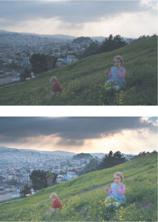
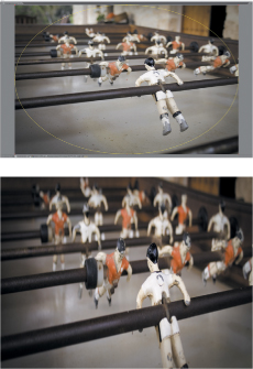
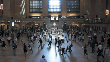
It’s helpful to create a rough assemble with camera animation as early in the process of creating your shot as possible, because it will tell you a lot about what you can get away with and what needs dedicated attention. The “Sky Replacement” section in Chapter 13 contains an example in which a flat card stands in for a fully dimensional skyline (Figure 9.15). The audience is focused on watching the lead character walk through the lobby, wondering what he has in his briefcase.
Figure 9.15. Prominent though it may appear in this still image, the audience isn’t focused on that San Francisco skyline outside the window. There’s no multiplaning as the camera moves because the background skyline is a still image; no one notices because viewer attention is on the foreground character.
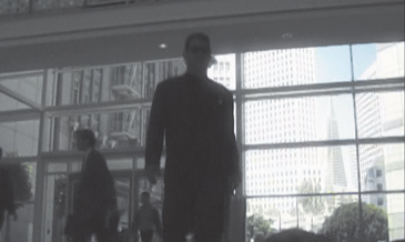
(Image courtesy of the Orphanage.)
Camera Animation
The most common confusion about the After Effects camera stems from the fact that, by default, it includes a point of interest, a point in 3D space at which the camera always points, for auto-orientation. The point of interest is fully optional, and thankfully with CS5 the toggle is no longer concealed in an obscure dialog but instead resides right in the Camera Settings (Figure 9.5).
A single-node camera is just like the ones we use in the real world, and thus is the one I find most useful and intuitive. For cases where you truly want the camera to orient around a point, the two-node camera’s Point of Interest property can even be linked to that point with an expression (and the pick whip for a moving target).
Tip
The Unified Camera tool (C) lets you use a three-button mouse to orbit, track, and zoom the camera without having to cycle through the tools. The better your graphics card, the snappier this tool will be.
The main problem with the two-node camera, besides that it has no direct equivalent in the physical world, is that it becomes cumbersome to animate a camera move that involves both the camera and its point of interest. To transform the camera and its point of interest together, don’t attempt to match keyframes for the two properties—this is sheer madness! Parent the camera to a null and translate that instead. This can help with the other surprise about the auto-oriented two-node camera, that it always maintains an upright position; cross over the X/Y plane above the center and the camera flips unless you do so via a parented null (or just use a one-node camera).
You can even orient the camera along its motion path, so that it maintains tangency (rotating in the direction it travels). For that, Layer > Transform > Auto Orient contains a toggle shown in Figure 9.15. You are still free to rotate a camera that is auto-oriented, but it usually gets a little hairy, since any change to a position keyframe changes the rotation too.
Notes
![]()
The Y axis is upside-down in After Effects 3D, just as in 2D; an increased Y value moves a layer downward.
The preceding points come into play only with more elaborate camera animations; more modest use of the 3D camera, such as a simple camera push, raises other more aesthetic questions.
Push and Zoom
A camera push moves the camera closer to the subject; a zoom lengthens the lens, reframing the shot to be closer up while the camera remains stationary. Figure 9.16 demonstrates the difference in perspective, which is just as noticeable with multiple 3D elements in After Effects as with objects in the real world. The zoom has a more extreme effect on the foreground/background composition of the shot and calls more attention to the camera itself. Zooming is most appropriate to reality or documentary shooting as it makes the viewer aware of the camera operator reframing the shot; in a push, the point of view moves naturally through the space like a human (or other nonmechanical) view would.
Figure 9.16. Frame a similar shot with a long (left) and wide (right) lens and you see the difference between a zoom and a push. A zoomed image has a flattened perspective.
Dramatic zooms for the most part had their heyday in 1960s-era Sergio Leone movies and have since declined dramatically in popularity, although they also re-create the live documentary feel of a camera operator reaching quickly for a shot. And that’s really the point; because your eye does not zoom, this move calls attention to the camera apparatus itself, and to the camera operator. Its use is therefore limited.
The push, on the other hand, is a dramatic staple. The question when creating one in After Effects is, does it require a 3D camera when you can simply scale 2D layers?
Notes
![]()
Animation > Keyframe Assistant > Exponential Scale is the old-school, pre-3D way to fake the illusion of a camera move on a 2D layer. There is no good reason to employ this feature when you can instead animate a 3D camera.
Scaling a 2D layer (or several, parented to a null) works for a small move; however, to re-create progression through z space, scaling is linear when it should be logarithmic—halve the distance from the camera to an object and it does not merely appear at twice its former size. A 3D camera move creates the proper scale difference naturally, making it simple to add eases, stops, and starts, a little bit of destabilization—whatever works, as if with an actual camera.
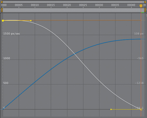
Natural camera motion contains keyframe eases (Chapter 2) for the human aspect. A little bit of irregularity lends the feeling of a camera operator’s individual personality (Figure 9.17), or even dramatic interest (hesitation, caution, intrigue, a leap forward—the possibilities are many).
Figure 9.17. The Graph Editor shows where you’ve created organic motion in ease curves, although the smoothness of this camera push as it eases to a stop may itself lack that extra human imperfection, which would also show up in the curves.
Lack of perspective can easily cause a move in or out of a completely 2D shot to look wrong. Likewise, all but the subtlest tracking and panning shots, crane-ups, and other more elaborate camera moves blow the 2.5D gag. Certain types of elements—soft, translucent organic shapes, such as clouds, fog, smoke, and the like—can be layered together and staggered in 3D space, fooling the eye into seeing 3D volume. Chapter 13 gives details.
Tip
Do you have a bunch of coplanar layers you’re making 3D just so you can push in on them? Precomp them together first to avoid little rounding errors that can easily occur where they overlap in 3D.
Camera Projection
Camera projection (or camera mapping) begins with a still photo or locked-off (stabilized) moving image. Imagine this image to be a slide, projected onto three-dimensional blank surfaces that match the position of planes in the image. As you move around, the projection holds its place on the surfaces, providing the illusion of depth and perspective (right up until the illusion breaks by going too far and revealing missing or stretched textures).
Notes
![]()
For this example, check out 09_camera_projection_basic on the disc, or try 09_camera_projection_advanced for the more complicated setup from previous editions.
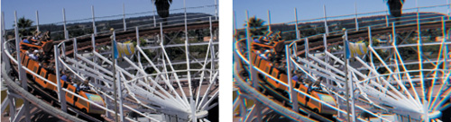
Previous editions of this book featured an ambitious animation of a still photo assembled by Stu Maschwitz that includes a couple of Hummers parked in the foreground. That project can still be found on the disc, but to simplify and clarify the process, here’s a simpler setup involving a locked-off shot across McCovey Cove (Figure 9.18).
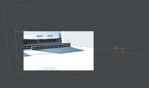
Suppose you desire a shot of the camera crossing the open water. A helicopter could do it, or possibly a very large crane, to some extent. Or you could plant a tripod on the shore, take a locked-off plate like the one provided, and project the scene to animate it yourself (Figure 9.19).
Figure 9.18. The difference between a simple reframe of the shot (left), which is a lot like a zoom (center), and a camera projection move, which is more like a dolly shot across the water (right), is not entirely subtle. The water surface appears soft in the projection because it is effectively scaled dramatically by the camera move.

Figure 9.19. It’s easier to see what’s really happening here, in Perspective view: The water, the waterfront wall, and stadium each have their own individual layer.
How is it that the one “texture” (the photo) sticks to the 3D objects? The steps to projecting any still image into 3D space are as follows:
- Begin with an image that can be modeled as a series of planes. In this case, the water and stadium are at least two planes, but there is the option of separating the front wall from the rest of the stadium, and even the sky and background skyscraper from that for a total of four or five planes. The more easily definable planes you can add, the more perspective you can derive.
- Create a white solid for the first dimensional plane in the image, the background. Enable 3D, and under Material Options, change Accepts Lights to Off.
- Add a camera named Projection Cam; if you know the Angle of View of your source image, add that value, but if not, it’s not necessarily a big deal.
- Add a Point light called Projector Light. Set its position to that of Projection Cam, then parent it to Projection Cam. Set Casts Shadows to On.
- Duplicate the source image, naming this layer Slide. Enable 3D, and in Material Options, change Casts Shadows to Only and Light Transmission to 100%.
- Slide not located properly? Add a null object called Slide Repo; set its position to that of Projection Cam, and parent it to Projection Cam. Now parent Slide to it, and adjust its scale downward until the image is cast onto the white planes, as if projected.
This much can be done for you by the CameraProjectionSetup script, other than specifying any unusual Angle of View (from step 3).
- Now it’s time to do a little—very little—3D modeling.
The backing plane is already set, although it will be further edited, but the first layer to add is the ground plane. You can simply duplicate and rename the solid Plane then enable multiple views to make it easy to rotate it 90 degrees and move it down and outward until it lines up with the edge of the water against the dock.
Having done that, I recommend at least one further breakdown. Duplicate the backing plane and name it Wall. Create a masked shape around the low wall above the water on the backing plane. Move the other layer (in the original position with no masks) back in z space, say 1000 pixels. Your setup should now begin to look something like that in Figure 9.19.
- With a more complicated setup, if planes that you know to be at perpendicular 90 degree angles don’t line up, adjust the Zoom value of the Projection Cam, scaling the model and slide as needed.
- Once everything is lined up, duplicate and disable Projection Cam, and rename the duplicate Anim Cam. Freely move this camera around the scene.
A simple move forward across the water reveals a flaw: The top of the wall was doubled as the camera moved closer to it. A simple move downward, closer to the surface of the water, not only solves this problem, it makes the effect of crossing the water more compelling.
Script
![]()
Included on the disc is CameraProjectionSetup, a script that Jeff Almasol and I designed to accomplish the basic camera projection setup automatically.
There’s no need to stop here. The bland, blue sky is just begging to be replaced, and that skyscraper to the right of frame could also use a plane of its own. Each of these presents a challenge: You need to mask or paint out the flag covering the building (I would just remove it) so it doesn’t travel with the building. The sky can be keyed out, but you should do that in a precomp since you can’t easily apply the matte to a projection.
You can freely add elements to the 3D environment of a camera-projected scene. If you wanted a logo to hover over the water or a giant dinosaur to lumber along the walkway beside the right field fence, these elements with alpha channel can be composited with the scene at the appropriate position (and scale) in x, y, and, most importantly, z space.
Notes
![]()
Camera Mapper is a standalone plug-in for camera projection from Digieffects that reduces the steps required for setup.
Depth of Focus
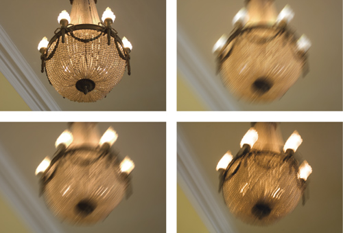
Elements out of focus have optical characteristics completely unique from those of ordinary blurred elements. Shallow depth of field creates a cinematic point of view by guiding the viewer’s attention, often while creating a lovely aesthetic. It’s worth re-creating in post even though doing so is a bit more trouble than simply blurring the image.
The standard consumer video camera has fairly limitless depth of field under normal shooting conditions, which can be seen as an advantage or a limitation. Shallow focal depth not only produces a beautiful image one would almost automatically call “cinematic,” it focuses the viewer’s attention and thus provides the director with a powerful storytelling tool. Not everyone subscribes to this aesthetic, of course: Orson Welles and his cinematographer Gregg Toland invented their own camera to increase the focal depth of shots in Citizen Kane to the maximum possible amount. But look at contemporary cinema and dramatic television and you will notice a lot of beautiful shots with very shallow depth of field.
It can be a lot of work to re-create depth effects in After Effects; it’s better to get them in camera if possible. Nonetheless, you can create specific cinematic blur effects such as a rack focus shot, in which the plane of focus shifts from a subject at one distance to another. This is a device to create anticipation and change the object of attention while creating a beautiful aesthetic.
Limited focal range is a natural part of human vision. Camera lenses contribute their own unique blur characteristics that in the contemporary era are considered aesthetically pleasing the world over—particularly in Japan, where the term boke (literally meaning “fuzzy”) was coined to describe the quality of out-of-focus light as viewed through a lens.
Boke and depth-of-field effects can be re-created in After Effects, using a combination of tools built in to the software, third-party tools to support the process, and a careful observation of optics and nature.
Notes
![]()
A solid description of boke with links lives on the Web at http://en.wikipedia.org/wiki/Bokeh.
Image Planes and Rack Focus
Any shot with distinct planes of depth can include a rack focus animation, in which the camera’s focus is pulled from one subject to another with a different depth. All you need is a focal point to animate and a depth of field narrow enough to create blur everywhere but the immediate plane of focus.
Narrow depth of field is created on a real camera by lowering the f-stop value, which lowers exposure as well. Not so with the After Effects 3D camera. Its Aperture and F-Stop settings (Figure 9.20) affect only focal depth, not exposure or motion blur. The two settings have an inverse relationship. F-Stop is the setting more commonly referenced by camera operators, and yet only Aperture appears as a property in the Timeline.
Figure 9.20. Check Enable Depth of Field in Camera Settings to activate Focus Distance (the distance in pixels of the focal point, which can be toggled to Lock to the Zoom). A low F-Stop (or high Aperture) with a Blur Level of 100% creates a shallow focal effect.
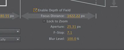
After Effects’ depth of field settings can be matched to those found in a camera report, provided that it includes the f-stop setting used when the footage was shot. If so, open up the Camera Settings dialog (Ctrl+Shift+Y/Cmd+Shift+Y, or double-click the Camera in the Timeline panel), check the box labeled Enable Depth of Field, and enter the value.
Offset at least one layer in z space so that it falls out of focal range. Now, in the Top view, set the Focus Distance (under Options) to match the layer that will be in focus at the beginning of the shot, add a keyframe, then change the Focus Distance at another frame to match a second layer later in the shot (Figure 9.21).
Figure 9.21. With Enable Depth of Field on, the Focus Distance is denoted by a red boundary line, easily viewed and animated in isometric views.

A static focus pull doesn’t look quite right; changing focus on a real camera will change the framing of the shot slightly. To sell the example shot, which starts on a view of the city and racks focus to reveal a sign in the foreground, I animate the camera pulling back slightly, augmented by a nice shift that then occurs in the offset planes of focus (Figure 9.22).
Figure 9.22. The final shot combines a rack focus with a gentle pullback, using ease keyframes to animate Position and Focus Distance.

Boke Blur
Racking focus in this manner generates camera blur that is accurate relative to the plane of focus, but it does not truly create the look of a defocused lens, because it is the lens itself that generates that look.
Boke features the phenomenon whereby points of light become discs of light (also called circles of confusion) that take on the character of the lens itself as they pass through the camera lens and aperture. Like lens flares (covered in Chapter 12) these are purely a phenomenon of the camera lens, not human vision; many shooters prize the beauty and suspense they can add to a shot. Illuminated out-of-focus elements in a shot are, after all, mysterious; visual intrigue is created as the shot resolves in or out of a wash of color and light (Figure 9.23).
Figure 9.23. With shallow depth of field, highlights in the foreground retain blur even in a focused shot.

A perfectly formed lens passes a defocused point of light to the back of the camera as a soft, spherical blur. A bright point remains bright but is enlarged and softened in the process. Ordinary blur of a low-dynamic-range image in 8 or 16 bit per channel color mode instead merely dims the highlights (Figure 9.24).
Figure 9.24. Begin with a source image that includes bright highlights (top left); blur it via conventional means, and the result is gray and desaturated (top right), unless the source image is HDR and the comp is 32 bpc (bottom left), which approaches the look of real camera motion blur (bottom right).

Most camera lenses are not perfect, so instead of perfect blurred spheres, boke spheres may be brighter toward the edges than in the middle. An anamorphic lens will show squashed spheres, and as with lens flares, the shape of the aperture itself may be visible in the circles, making them hexagonal (or pentagonal, and so on, depending on the number of blades in the opening). Believe it or not, if you skip this level of detail, the result is far less likely to succeed even with the casual viewer.
Go for Boke
To accurately create the bloom of highlights as they are blurred requires 32 bit per channel color and source highlights that are brighter than what would be called full white in 8 or 16 bpc. The process of creating such an image is explored and explained in Chapter 11.
The Lens Blur effect does not operate in 32 bpc—it instead mimics the behavior of bright highlights through a lens. It’s more or less a direct port from Photoshop; as such, it can be slow and cumbersome in After Effects. It won’t blur beyond 100 pixels, and the effect does not understand nonsquare pixels (it creates a perfect circle every time).
Instead of 3D camera or layer data, Lens Blur can use a Depth Map Layer, using pixel values (brightness) from a specified Depth Map Channel. You can rack focus by adjusting Blur Focal Distance. Iris Shape defines polygons around the highlights, corresponding to the number of blades in the iris; you can also specify Iris Blade Curvature and Iris Rotation (this rotates the polygon).
Notes
![]()
The most respected third-party tool for lens blurs is Frischluft’s Lenscare. The default settings are not reliable, but with adjustments and depth maps (for 3D footage), you can derive some lovely results (you’ll find Lenscare at www.frischluft.com and on the book’s disc).
The actual amount of blur is determined by Iris Radius, the bloom by Specular Threshold (all pixels above this value are highlights) and Specular Brightness, which creates the simulation of highlight bloom. These are the controls you’ll tweak most (Figure 9.25).
Figure 9.25. The result of a Lens Blur effect (left) doesn’t look so hot compared to the real thing (center), while the Lenscare plug-in from Frischluft (right) is remarkably close. Sometimes the tools matter.

The Noise controls are designed to restore noise that would be removed by the blur operation; they don’t relate to the blur itself and can be ignored in favor of grain techniques described in the following section.
By no means do the settings in Lens Blur (or for that matter, third-party alternatives such as Lenscare from Frischluft) exhaust the possibilities for how defocused areas of an image might appear, especially when illuminated. Keep looking at the reference and thinking of ways to re-create what you see in it (Figure 9.26).
Figure 9.26. Does an image with shallow depth of field look more cinematic? What do you see happening in the defocused background?
Grain
Once the image passes through the camera lens and is recorded, it takes on another characteristic of motion pictures: grain. Grain is essentially high-frequency noise readily apparent in each channel of most recorded footage, although progress in image gathering technology has led to a gradual reduction of grain. Digitally produced animations such as Pixar movies have no native grain at all, save when the story calls for a deliberate re-creation of archival footage, as in the opening scenes of The Incredibles.
Grain can, however, be your friend, subtly adding life to a static background or camouflaging foreground edge detail. It is not simply switched on or off, but requires careful per-channel adjustment. There are two basic factors to consider:
• size of the grain, per channel
• amount of grain, or amount of contrast in the grain, per channel
Notes
![]()
Excessive grain is often triggered by a low amount of scene light combined with a higher effective ASA, particularly with lower-quality image sensors.
The emphasis here is that these factors typically vary from channel to channel. Blue is almost universally the channel likeliest to have the most noise; happily, the human eye is less sensitive to blue than red or green.
How much grain is enough? As with color in Chapter 5, the goal is typically to match what’s there already. If your shot has a background plate with the proper amount of grain in it, match foreground elements to that. A computer-generated still or scene might have to be grain-matched to surrounding shots.
Grain Management Strategies
After Effects includes a suite of three tools for automated grain sampling, grain reduction, and grain generation: Add Grain, Match Grain, and Remove Grain. Add Grain relies on your settings only, but Match Grain and Remove Grain can generate initial settings by sampling a source layer for grain patterns.
I don’t always recommend the automated solution, but in this case, Match Grain usually comes up with a good first pass at settings; it can get you 70% to 80% there and is just as adjustable thereafter. To refine grain settings:
- Look for a section of your source footage with a solid color area that stays in place for 10 to 20 frames. Most clips satisfy these criteria (and those that don’t tend to allow less precision).
- Zoom 200% to 400% on the solid color area, and create a Region of Interest around it. Set Work Area to the 10 or 20 frames with little or no motion.
- Add a solid small enough to occupy part of the region of interest. Apply a Ramp effect to the solid, and use the eyedropper tools to select the darkest and lightest pixels in the solid color area of the clip. The lack of grain detail in the foreground gradient should be clearly apparent (Figure 9.27).
Figure 9.27. A gradient is placed right over the talent’s head as a reference for grain matching the window above it. Even without slamming the image it’s clear that the added window looks too flat in this grainy scene, but slamming with the addition of a gradient gives you a clear target.
- Apply the Match Grain effect to the foreground solid. Choose the source footage layer in the Noise Source Layer menu. As soon as the effect finishes rendering a sample frame, you have a basis from which to begin fine-tuning. You can RAM preview at this point to see how close a match you have. In most cases, you’re not done yet.
- Twirl down the Tweaking controls for Match Grain, and then twirl down Channel Intensities and Channel Size. You can save yourself a lot of time by doing most of your work here, channel by channel.
- Activate the green channel only in the Composition panel (Alt+1/Opt+1) and adjust the Green Intensity and Green Size values to match the foreground and background. Repeat this process for the green and blue channels (Alt+2/Opt+2 and Alt+3/Opt+3). If you don’t see much variation channel to channel, you can instead adjust overall Intensity and Size (Figure 9.28). RAM preview the result.
Figure 9.28. In this unusual case, there is little variation of grain channel to channel, and the automatic match is pretty good; a slight boost to the overall Intensity setting under the Tweaking controls does the trick.

- Adjust Intensity, Size, or Softness controls under Tweaking according to what you see in the RAM preview. You may also find it necessary to reduce Saturation under Color, particularly if your source is film rather than video.
In most cases, these steps yield a workable result (Figure 9.29). The effect can then be copied and pasted to any foreground layers that need grain. If the foreground layer already contains noise or grain, you may need to adjust the Compensate for Existing Noise percentage for that layer.
Figure 9.29. Even in this printed figure, the matching grain is somewhat evident. Grain matching is often best reviewed in motion with a boosted exposure.
Obviously, whole categories of controls within Match Grain remain untouched with this approach; the Application category, for example, contains controls for how the grain is blended and how it affects shadows, midtones, and highlights individually. These are typically overkill, as are the Sampling and Animation controls, but how far you go in matching grain before your eye is satisfied is, of course, up to you.
Close-up: Use Noise as Grain
![]()
Prior to the addition of Add Grain and Match Grain to After Effects version 6.5 Professional, the typical way to generate grain was to use the Noise effect. The main advantage of the Noise effect over Match Grain is that it renders about 20 times faster. However, After Effects doesn’t make it easy for you to separate the effect channel by channel, and scaling requires a separate effect (or precomping).
You can use three solid layers, with three effects applied to each layer: Shift Channels, Noise, and Transform. Use Shift Channels to set each solid to red, green, or blue, respectively, set Blending Modes to Add, and set their Opacity very low (well below 10%, adjusting as needed). Next, set the amount of noise and scale it via the Transform effect.
If the grain is meant to affect a set of foreground layers only, hold them out from the background plate either via precomping or track mattes. If this sounds complicated, it is, which is why Match Grain is preferable unless the rendering time is really killer.
Grain Removal
Removing grain, or sharpening an image in general, is an entirely different process from adding grain. On a well-shot production, you’ll rarely have a reason to reach for the Remove Grain tool.
If you do, the reason for doing so may be unique to your particular footage. In such cases, you may very well find that leaving Remove Grain at the default settings gives you a satisfactory result. If not, check into the Fine Tuning and Unsharp Mask settings to adjust the grain.
Remove Grain is often best employed stealthily—not necessarily across the entire frame (Figure 9.30), or as part of a series of effects. It is a reasonably sophisticated solution (compared with the current alternatives) that can really help in seemingly hopeless situations.
Figure 9.30. The left side of frame is clearly less grainy than the right as a result of applying Remove Grain and letting it automatically sample the footage.
Grain removal can also help with grain matching by allowing you to start with a clean slate instead of applying grain over more grain. When matching grainy footage to other footage with a different grain structure or pattern, it’s a necessary step.
When to Manage Grain
The most obvious candidates for grain addition are computer-generated or still image layers that lack the moving grain found in film or video footage. As soon as your shot has to match anything that came from a camera, and particularly in a large format such as HD or film, you must work with grain.
Tip
If you’re using Remove Grain to improve a bluescreen or greenscreen key, consider applying the result as an alpha track matte. This offers the best of both worlds: a clean matte channel and preservation of realistic grain on the source color layer.
Blurred elements may also need grain addition, even if they originate as source footage. Blurry source shots contain as much grain as focused ones because the grain is an artifact of the medium recording the image, not the subject itself. Elements that have been scaled down in After Effects contain scaled-down grain, which may require restoration. Color keying can also suppress grain in the channel that has been keyed out.
Other compositing operations will instead enhance grain. Sharpening, unless performed via Remove Grain, can strongly emphasize grain contrast in an element, typically in a not-so-desirable manner. Sharpening also brings out any nasty compression artifacts that come with footage that uses JPEG-type compression, such as miniDV video.
Lack of grain, however, is one of the big dead giveaways of a poorly composited shot. It is worth the effort to match the correct amount of grain into your shot even if the result isn’t apparent as you preview it on your monitor.
Lens Optics & Looks
The real fun comes when you start to add your own recipe of looks to an image, whether to make it look as though it were shot on some different medium, or to make it look as cinematic as possible. In either case, you will find yourself effectively degrading your footage: adding effects related to lens limitations, cropping the image to be shorter (and thus appear wider), pushing the color into a much more limited, controlled range.
The question of how to create a cinematic image without a professional film crew (or budget) is greatly expanded upon in The DV Rebel’s Guide: An All-Digital Approach to Making Killer Action Movies on the Cheap (Peachpit Press, 2006), by Stu Maschwitz. The first chapter lists the major factors that influence production value. Many of these, including image and sound quality, location, and lighting, cannot be “fixed in post,” which must be why Stu’s book includes a bunch of information on how to actually shoot.
Achieving a particular look is well within the realm of tricks you can pull off consistently in After Effects. You can take control of the following to develop a look and maximize production value:
• Lens artifacts. We love defects! In addition to the aforementioned boke and other defocus imperfections, along with chromatic aberration, are such filmic visual staples as the vignette and the lens flare.
• Frame rate. Change this to alter the very character of footage. For the most part, frame rate needs to be determined when shooting in order for things to go smoothly.
• Aspect ratio. The format of the composition makes a huge perceptual difference as well. Wide connotes big-budget Hollywood epic and thus is not always appropriate.
• Color look. Nothing affects the mood of a given shot like color and contrast. It’s a complex subject revisited in Chapter 12.
Close-up: Garbage In, Garbage Out
![]()
You don’t need me to tell you how difficult it is to bring a poorly shot image back from the dead, but check The DV Rebel’s Guide for a thorough rundown of factors that go into a well-shot image. If possible go on set to help eliminate flaws that will be difficult to fix in post. Among the less obvious points from the book:
• When shooting digitally, keep the contrast low and overall light levels well below maximum; you are shooting the negative, not the final (Figure 9.31).
Figure 9.31. Shooting low-contrast (top) with a camera that has a healthy contrast range allows you to bring out hidden detail and color, even tone-mapping to do so only in specific areas of frame (bottom).
• If using a small, light camera, mount it to something heavy to move it; that weight reads to the viewer as more expensive and more natural motion.
Lens Artifacts and Other Happy “Accidents”
Reality as glimpsed by the camera includes lens artifacts (visual phenomena that occur only through a camera, not the lens of your eye) such as lens distortion and lens blur (or boke), but that’s not all. Also on your palette are “flaws” that good cinematographers avoided right up until Easy Rider showed that a lens flare goes with a road movie the way mustard goes with a hot dog.
Vignettes, the darkening around the corners of the frame that results from a mismatch between a round lens and a rectangular frame (when the frame is too large for the image) are almost completely avoidable these days, yet they’ve never been more popular among designers and photo graders.
Chromatic aberration is exactly the combination it sounds to be: an aberration (which sounds bad) of color (we all like that). It, too, is always the result of a mismatch between a lens and a camera and rarely shows up unless the shooter is doing something crazy or using a very cheap camera.
All of these effects provide texture, variety, and spontaneity to an image; in other words, they can bring a shot to life.
The Lens Flare
When a bright light source such as the sun appears in shot it causes secondary reflections to bounce around among the lens elements; there’s so much light, it reflects back on the surface of the many individual lenses that make up what we call a lens. Your eye can resolve an image using one very flexible lens, but camera lenses beyond the simplest Brownie (one lens) or pinhole (none) camera require a series of inflexible glass lens elements. A complex zoom lens might consist of 20 elements. Each is coated to prevent the reflections that create flares, but there’s a limit.
Because they occur within the lens, lens flares appear superimposed over the image. If the light source is partially occluded by a foreground object or figure, the flare may diminish or disappear, but you’ll never see a full-strength lens flare partially blocked by a foreground subject. Each flare appears as a complete disc, ring, star, or other shape.
Artists love lens flares and can develop the bad habit of playing a bit fast and loose with them. As with anything, the game is to keep it real first, and then bend the rules around to the look you want, if necessary. Fundamentally, only if the shot was clearly taken with a long lens do you have any business with the types of crazy multi-element flares you get, for example, by the default setting of the paltry Lens Flare effect that ships with After Effects.
In addition to the glass elements, aperture blades contribute to the appearance of flares. Their highly reflective corners result in streaks, the number corresponding to the number of blades. As with boke, the shape of the flares might correspond to the shape of the aperture (a pentagon for a five-sided aperture, a hexagon for six). Dust and scratches on the lens even reflect light.
The Lens Flare effect that ships with After Effects is limited to three inflexible 8 bit per channel presets and had become old a decade ago. Knoll Light Factory is highly customizable and is derived from careful study of lens behaviors; it’s being updated as of press time. The major newcomer on the scene is Optical Flares from Video Copilot.
Chapter 12 shows that flares can also be caused by bright specular pings and other reflected highlights in a scene and offer a further opportunity to enhance the reality of a shot. These can be re-created with those same plug-in effects, or by creating your own and using a blending mode (typically Add) to apply it.
Script
![]()
Designing your own array of lens elements isn’t out of the question, and in order to array them in a classic mult-element zoom lens arrangement, you can use Trajectory (http://aescripts.com/trajectory/), a script from Michael Cardeiro, that aligns layers between two null objects.
The Vignette
When the edges of the frame go dark, our attention becomes more focused on what’s at the center. Lens manufacturers have gone to significant trouble to eliminate this effect when shooting, but pay attention to the corners of the images you see and you’ll notice an awful lot of vignettes added in post these days.
Vignette controls are included with “film look” software such as Magic Bullet Looks, but this is also an easy effect to create:
- Create a black solid the size of your frame as the top layer and name it Vignette.
- Double-click the Ellipse tool in the toolbar; an elliptical mask fills the frame.
- Highlight the layer in the Timeline and press F to reveal Mask Feather.
- Increase the Mask Feather value a lot—somewhere in the low triple digits is probably about right.
- Lower the Opacity value (T) until the effect looks right; you might prefer a light vignette (10% to 15%) or something heavier (40% to 50%).
A vignette would be elliptical or round depending on whether it was shot with an anamorphic lens (Figure 9.32). There would be no reason for a lens vignette to be offset, but you’re not limited to such realistic limitations if it suits your scene to offset and rotate a soft ellipse. Generally, vignettes look best just below the threshold where we would clearly notice that the corners and edges have gone a little dark.
Figure 9.32. A vignette is created with a feathered mask applied to a solid (top). If the image is reframed for display in another format, such as anamorphic, you may have to use that framing instead of the source (bottom).
Chromatic Aberration
Chromatic Aberration is an even rarer visual phenomenon. This fringing or smearing of light that occurs when a lens cannot focus various colors on the spectrum to a single point, because of the differing wavelengths, yields a rainbow of colors something like that of light passing through a prism. The effect is more pronounced closer to the edge of frame. It can occur during projection as well; alas, I have seen it in low-budget cinemas.
Like lens flares and boke, a little bit of aberration can bring a scene life and spontaneity. Some simple steps to re-create this effect at its most basic level:
- Duplicate the layer twice and precompose all three.
- Use the Shift Channels effect to leave only red, green, or blue on for each layer (so you end up with one of each).
- Set the top two layers to Add mode.
- Scale the green channel to roughly 101% and the blue channel to roughly 102%.
- Add a small amount of Radial Blur (set to Zoom, not the default Spin).
Script
![]()
ft-Cubic Lens Distortion by François Tarlier (http://aescripts.com/ft-cubic-lens-distortion/) is in fact a pixel bender plug-in but has in common with scripts that it is donation-ware and freely available to try. It uses the Syntheyes cubic lens distortion algorithm and can not only add or remove lens distortion but apply chromatic aberration to a shot.
A before and after comparison using this setup appears in Figure 9.33. Better yet, pick up Satya Meka’s Separate RGB effect (http://aescripts.com/separate-rgb/) where you can name your own price. This Pixel Bender plug-in lets you transform individual channels of color directly.
Figure 9.33. A simulation of chromatic aberration (right), the color ringing that is caused when different wavelengths of light have different focal lengths; most lenses correct for it with an added diffractive element (left).
Frame Rate and Realism
It’s no accident that film images are still displayed at 24 frames per second nearly a century after this seeming limitation was imposed, and that even the newest electronic formats that can be optimized for 30 or 60 also tend to gain legitimacy when they add a 24p, or full frame 24 fps mode, but it makes no sense. Why not gather more data if you can?
The answer does not seem entirely logical. The truth seems to be that your eye has an effective “refresh rate” somewhere slightly upward of 60 times per second, and so the 60 interlaced fields of 29.97 American television feel a lot like direct reality. 24 fps, on the other hand, is barely above the threshold where the eye loses persistence of vision, the phenomenon that allows it to see continuity from still images shown in series.
Close-up: 29.97 fps Is for Soap Operas and Reality Television
![]()
The debate about raising the frame rate above the 24 fps you see in the cinema has been raging since long before the digital era. The invention of videotape in the 1950s made it cheap and fast to record imagery more directly in the format of television.
One particular experiment from this era stands out. For six episodes, the producers of The Twilight Zone tried tape before they evidently realized it was ruining the show’s mystique. Video’s higher frame rate transformed this masterpiece of irony and suspense into something resembling a soap opera. Judge for yourself—check out Season 2’s videotaped episodes: “Static,” “Night of the Meek,” “The Lateness of the Hour,” “The Whole Truth,” “Twenty-Two,” or “Long Distance Call.” The experiment was quickly ended and in five total seasons the show never appeared on videotape again.
Cinema may have gone for 24 fps due to limitations of equipment and money. Fewer frames per second meant a sizable reduction in film stock costs. If so they accidentally also got with this compromise the more ephemeral and dream-like quality that goes with it. As with shallow depth of field (earlier in this chapter) and color reduction (ahead), less can be more. Once again, re-creating cinematic reality requires that you reduce data.
After Effects is quite forgiving about letting you change frame rates midstream compared with most video applications; details on how the conversion actually works appeared back in Chapter 2. However, it is very difficult to convert 29.97 fps footage to 24 fps without introducing a lurching cadence to smooth motion as every sixth frame is dropped. When working at 29.97 fps, it can still make sense to animate and render whole frames instead of interlacing to 60 fields per second to give a little more of that cinematic quality to the result.
Format and Panoramas
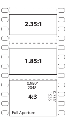
As the world transitions from standard-definition to high-definition broadcast television, formats are undergoing the same transition that they made in film half a century ago. The nearly square 4:3 aspect is being replaced as standard by the wider 16:9 format, but 1.85 Academy aperture and 2.35 Cinemascope also appear as common “widescreen” formats.
In response to the growing popularity of television in the 1950s, Hollywood conjured up a number of different widescreen formats through experiments with anamorphic lenses and film stocks as wide as 70 mm. These systems—CinemaScope, VistaVision, Panavision, and so on—themselves faded away but not without changing the way films are displayed.
Notes
![]()
The numbers “1.85” and “2.35” or “2.4” give the width, relative to a height of 1, so it’s like saying 1.85:1 or 2.39:1 (the actual widescreen ratio). The 16:9 format, which has become popular with digital video and HD, is equivalent to a 1.77:1 ratio, slightly narrower than Academy, but wide compared to the standard television format of 4:3 (1.33: 1), which is also that of old movies such as Casablanca.
Standard 35 mm film has an aspect ratio of 4:3, which is not coincidentally the same as a television. Movies tend to be filmed in this format as if originally intended for the small screen. When shown in a theater using a widescreen aspect of 1.85:1 (also known as 16:9, the HDTV standard) or 2.39:1 (Cinemascope), the full 4:3 negative is cropped (Figure 9.34). The wider formats also tend to have been shot anamorphically, squeezing the wider image into the narrower frame.
Figure 9.34. “Wide” film formats would more accurately be called “shorter” because they typically involve cropping the original 4:3 image.
16:9 widescreen high-definition televisions and projectors have taken over, so clearly the wider aspect ratio won. Is 2.4:1 even better? This format seems to go best with sweeping vistas: the majestic desert of Lawrence of Arabia and the Millennium Falcon’s jump to light speed. If you choose this format, you are saying to your audience that they should expect to see some pretty spectacular views, and if you don’t deliver, the format choice may disappoint.
Also, and ironically, when shown in HD the widescreen image is the lowest resolution—only 800 pixels tall, making small detail less discernable, especially once compression has been applied.
Less Color Is More
This entire section has been about how corrupting, degrading and reducing data in an image can bring it to cinematic life. Color grading can transform an ordinary image into one that resonates emotionally, and it does so, paradoxically, by reducing the accuracy and range of the hues in the source image.
In her book If It’s Purple, Someone’s Gonna Die, author Patti Bellantoni explores many scenes from cinema whose color palette is dominated by one color, and why this choice resonates with us, including analogues with other visual art forms such as paintings. It’s surprisingly rare for a shot in a movie to be dominated by more than three shades, and there is no doubt that the dominant color influences the emotional impact of the scene.
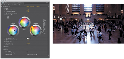
Figures 9.35 through 9.38 offer a simple demonstration of how color choices can influence the look of a scene, along with showing the primary corrections that were made in Colorista to achieve them.
Figure 9.35. The source image does not by itself convey any particular emotion through its color palette, although the natural vignette-like effect caused by the backlight does focus one’s attention.
(Source clip courtesy of Eric Escobar.)
Figure 9.36. A miracle is about to occur.
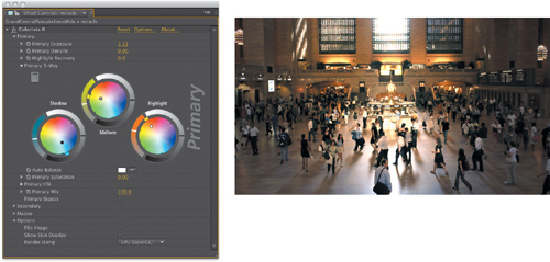
Figure 9.37. Does this city care about people, or just money and efficiency?

Figure 9.38. The day the world almost came to an end.
Primary color correction—creating the look in post—typically is done via a three-way color corrector such as is found in Color Finesse or Colorista. You might start by pushing shadows in one direction—typically the cooler blue/green range to offset the next step, pushing highlights in the yellow/red (but truly, orange) direction. The midtone might then set the mood.
This process may reduce the range of hues in the shot but emotionally, done right, it will make the frame sing. However, this is merely one of many methods one could use to establish a look. For more ideas, watch others as they work in videos on color correction, as are freely available at places like Red Giant Software. This topic is probably worthy of a book of its own.
Overall, if you’re new to the idea of developing a color look for a film or sequence, look at references. Study other people’s work for the effect of color on the mood and story in a shot, sequence, or entire film, and give yourself the exercise of re-creating it. Don’t be hard on yourself, just notice what works and what’s missing. Once you have that down, you’re ready to create your own rules and even break those set by others.
Conclusion
And really, this chapter just scratched the surface of what’s possible. You can and should always look for new methods to replicate the way that the camera sees the world, going beyond realism to present what we really want to see—realism as it looks through the lens.