
Chapter 3. Introduction to Column Distillation
Distillation is by far the most common separation technique in the chemical process industry, accounting for 90% to 95% of the separations. The approximately 40,000 distillation columns in use account for approximately 40% of the energy use by the United States’ chemical process industry—equivalent to a staggering 1.2 million barrels of crude oil a day (Humphrey and Keller, 1997).
This chapter introduces how continuous distillation columns work and serves as the lead to a series of nine chapters on distillation. The basic calculation procedures for binary distillation are developed in Chapter 4. Multicomponent distillation is introduced in Chapter 5, detailed computer calculation procedures for multicomponent systems are developed in Chapter 6, and simplified shortcut methods are covered in Chapter 7. More complex distillation operations, such as extractive and azeotropic distillation, are the subject of Chapter 8. Chapter 9 switches to batch distillation, which is commonly used for smaller systems. Detailed design procedures for both staged and packed columns are discussed in Chapter 10. Finally, Chapter 11 looks at the economics of distillation and methods to save energy (and money) in distillation systems.
3.0 Summary—Objectives
In this chapter we introduce the idea of distillation columns and learn how to do external balances. After finishing this chapter, you should be able to satisfy the following objectives:
1. Explain how a countercurrent distillation column physically works
2. Sketch and label the parts of a distillation system; explain the operation of each part and the flow regime on the trays
3. Explain the difference between design and simulation problems; list the specifications for typical problems
4. Write and solve external mass and energy balances for binary distillation systems
3.1 Developing a Distillation Cascade
In Chapter 2, we learned how to do the calculations for flash distillation. Flash distillation is a very simple unit operation, but in most cases it produces a limited amount of separation. In Problems 2.D2, 2.D5, 2.D30, and 2.D32 we saw that more separation could be obtained by adding on (or cascading) more flash separators. The cascading procedure can be extended into a process that produces one pure vapor and one pure liquid product. First, we could send the vapor streams to additional flash chambers at increasing pressures and the liquid streams to flash chambers with decreasing pressures, as shown in Figure 3-1. Stream V1 will have a high concentration of the more volatile component (MVC), and stream L5 will have a low concentration of the MVC. Each flash chamber in Figure 3-1 can be analyzed by the methods developed previously.
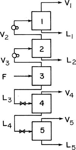
One difficulty with the cascade shown in Figure 3-1 is that the intermediate product streams, L1, L2, V4, and V5, are of intermediate concentration and need further separation. Of course, each of these streams could be fed to another flash cascade, but then the intermediate products from those cascades would have to be sent to additional cascades, and so forth. A much cleverer solution is to use the intermediate product streams as additional feeds within the same cascade.
Consider stream L2, which was generated by flashing part of the feed stream and then condensing part of the resulting vapor. Since the material in L2 has been vaporized once and condensed once, it probably has a concentration close to that of the original feed stream. (To check this, you can do the appropriate flash calculation on a McCabe-Thiele diagram.) Thus it is appropriate to use L2 as an additional feed stream to stage 3. However, since p2 > p3, its pressure must first be decreased.
Stream L1 is the liquid obtained by partially condensing V2, the vapor obtained from flashing vapor stream V3. After vaporization and then condensation, stream L1 will have a concentration close to that of stream V3. Thus it is appropriate to use stream L1 as an additional feed to stage 2 after pressure reduction.
A similar argument can be applied to the intermediate vapor products below the feed, V4 and V5. V4 was obtained by partially condensing the feed stream and then partially vaporizing the resulting liquid. Since its concentration is approximately the same as the feed, stream V4 can be used as an additional feed to stage 3 after compression to a higher pressure. By the same reasoning, stream V5 can be fed to stage 4.
Figure 3-2 shows the resulting countercurrent cascade, so called because vapor and liquid streams go in opposite directions. The advantages of this cascade over the one shown in Figure 3-1 are that there are no intermediate products, and the two end products can both be pure and obtained in high yield. Thus V1 can be almost 100% of MVC and contain almost all of the MVC in the feed stream.
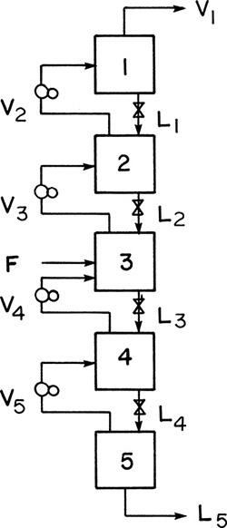
Although a significant advance, this variable pressure (or isothermal distillation) system is seldom used commercially. Operation at different pressures requires a large number of compressors, which are expensive. It is much cheaper to operate at constant pressure and force the temperature to vary. Thus, in stage 1 of Figure 3-2 a relatively low temperature would be employed, since the concentration of the MVC, which boils at a lower temperature, is high. For stage 5, where the LVC is concentrated, the temperature would be high. To achieve this temperature variation, we can use heat exchangers (reboilers) to partially vaporize the liquid streams. This is illustrated in Figure 3-3, where partial condensers and partial reboilers are used.

FIGURE 3-3. Countercurrent cascade of flash chambers with intermediate reboilers and condensers, p = constant; T1 < T2 < T3 < T4 < T5
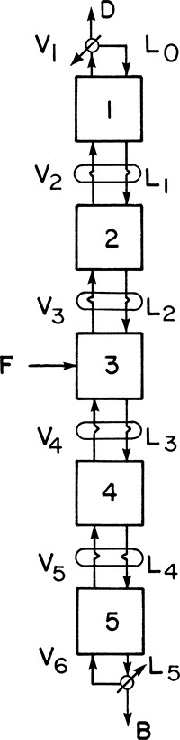
The cascade shown in Figure 3-3 has a decreasing vapor flow rate as we go from the feed stage to the top stage and a decreasing liquid flow rate as we go from the feed stage to the bottom stage. Operation and design will be easier if part of the top vapor stream V1 is condensed and returned to stage 1 and if part of the bottom liquid stream L5 is vaporized and returned to stage 5, as illustrated in Figure 3-4. This allows us to control the internal liquid and vapor flow rates at any desired level. Stream D is the distillate product, while B is the bottom product. Stream L0 is called the reflux and V6 is the boilup.

FIGURE 3-4. Countercurrent cascade of flash chambers with reflux and boilup, p = constant; T1 < T2 < T3 < T4 < T5
The use of reflux and boilup allows for a further simplification. We can now apply all of the heat required for the distillation to the bottom reboiler, and we can do all of the required cooling in the top condenser. The required partial condensation of intermediate vapor streams and partial vaporization of liquid streams can be done with the same heat exchangers as shown in Figure 3-5. Here stream V2 is partially condensed by stream L1 while L1 is simultaneously partially vaporized. Since L1 has a higher concentration of MVC, it will boil at a lower temperature, and heat transfer is in the appropriate direction. Since the heat of vaporization per mole is usually approximately constant, condensation of 1 mole of vapor will vaporize approximately 1 mole of liquid. Thus liquid and vapor flow rates tend to remain constant. Heat exchangers can be used for all other pairs of passing streams: L2 and V3, L3 and V4, and L4 and V5.
Note that reflux and boilup are not the same as recycle. Recycle returns a stream to the feed to the process. Reflux and boilup first change the phase of a stream and then return the stream to the same stage the vapor (or liquid) was withdrawn from. This return at the same location helps increase the concentration of the component that is concentrated at that stage.
The cascade shown in Figure 3-5 can be further simplified by building the entire system in a column instead of as a series of individual stages. The intermediate heat exchange can be done very efficiently with the liquid and vapor in direct contact on each stage. The result is a much simpler and cheaper device. A schematic of such a distillation column is shown in Figure 3-6.

FIGURE 3-6. Distillation column: (A) schematic of five-stage column (T1 < T2 < T3 < T4 < T5 < T6), (B) photograph of distillation columns courtesy of APV Equipment, Inc. Tonawanda, NY.
The cascade shown in Figure 3-6 is the usual form in which distillation is done. Because of the repeated vaporizations and condensations as we go up the column, the top product (distillate) can be highly concentrated in the MVC. The section of the column above the feed stage is known as the enriching or rectifying section. The bottom product (bottoms) is highly concentrated in the less volatile component (LVC), since the MVC has been stripped out by the rising vapors. This section is called the stripping section.
The distillation separation works because every time we vaporize material, the MVC tends to concentrate in the vapor, and the LVC in the liquid. As the relative volatility α, Eq. (2-21), of the system decreases, distillation becomes more difficult. If α = 1.0, the liquid and vapor will have the same composition, and no separation will occur. Liquid and vapor also have the same composition when an azeotrope occurs. In this case one can approach the azeotrope concentration at the top or bottom of the column but cannot get past it except with a heterogeneous azeotrope (see Chapter 8). The third limit to distillation is the presence of either chemical reactions between components or decomposition reactions. This problem can often be controlled by operating at lower temperatures using vacuum or steam distillation (see Chapter 8).
While we are still thinking of flash distillation chambers, a simple but useful result can be developed. In a flash chamber a component will tend to exit in the vapor if yiV > xiL. Rearranging this, if KiV/L > 1, a component tends to exit in the vapor. In a distillation column this means that components with KiV/L > 1 tend to exit in the distillate, and components with KiV/L < 1 tend to exit in the bottoms. This is only a qualitative guide, since the separation on each stage is far from perfect, and Ki, V, and L all vary in the column; however, it is useful.
3.2 Distillation Equipment
It will be helpful if you develop a basic understanding of distillation equipment before studying the design methods. A detailed description of equipment is included in Chapter 10. Figure 3-6A is a schematic of a distillation column, and Figure 3-6B is a photograph of several columns.
The column is usually metal and has a circular cross section. It contains trays (plates or stages) where liquid-vapor contact occurs. The simplest type of tray is a sieve tray, which is a sheet of metal with holes punched into it for vapor to pass through. This is illustrated in Figure 3-7. The liquid flows down from the tray above in a downcomer and then across the sieve tray where it is intimately mixed with the vapor. The vapor flowing up through the holes prevents the liquid from dripping downward, and the metal weir acts as a dam to keep a sufficient level of liquid on the plate. The liquid that flows over the weir is a frothy mixture containing a lot of vapor. This vapor disengages in the downcomer so that clear liquid flows into the stage below. The space above the tray allows for disengagement of liquid from vapor and needs to be high enough to prevent excessive entrainment (carryover of liquid from one stage to the next). Distances between trays vary from 2 to 48 inches and tend to be greater the larger the diameter of the column.
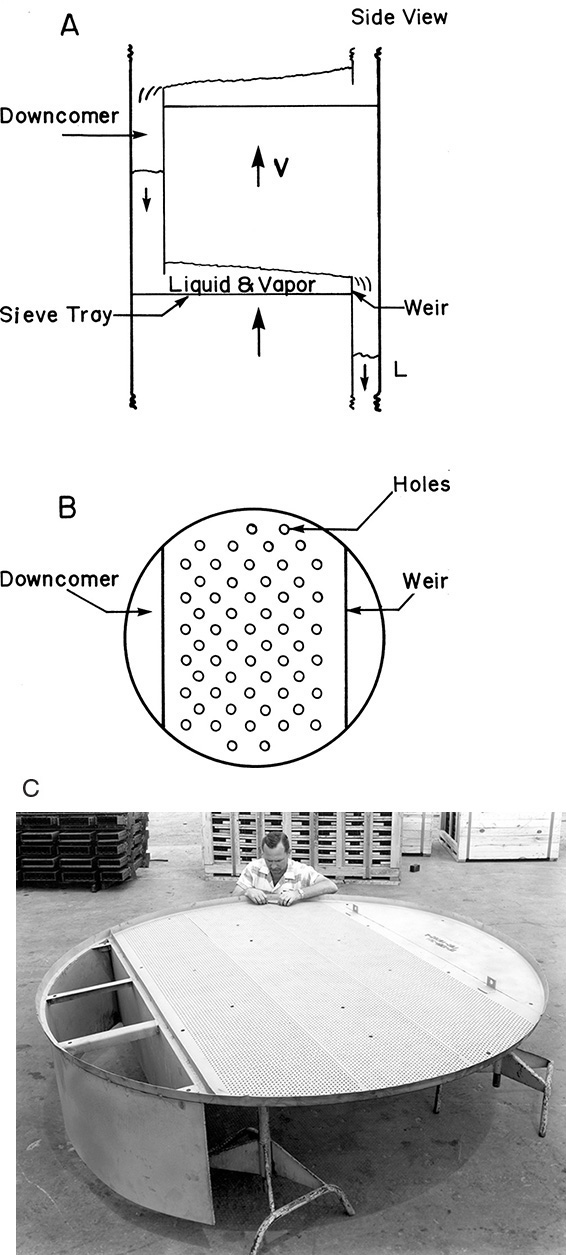
FIGURE 3-7. Sieve trays: (A) schematic side view, (B) schematic top view, (C) photograph courtesy of Glitsch, Inc.
To say that there is liquid on the tray is an oversimplification. In practice, any one of four distinct flow regimes can be observed on trays, depending on the gas flow rate. In the bubble regime the liquid is close to being a stagnant pool with distinct bubbles rising through it. This regime occurs at low gas flow rates. The poor mixing causes poor liquid and vapor contact, which results in low stage efficiency. Because of the low gas flow rate and low efficiency, the bubble regime is undesirable in commercial applications.
At higher gas flow rates the stage will often be in a foam regime. In this regime the liquid phase is continuous and has fairly distinct bubbles rapidly rising through it. There is distinct foam similar to the head resting atop the liquid in a mug of beer. Because of the large surface area in foam, the area for vapor-liquid mass transfer is large, and stage efficiency may be quite high. However, if the foam is too stable, it can fill the entire region between stages. When this occurs, entrainment becomes excessive, stage efficiency drops, and the column may flood (fill up with liquid and become inoperative). Excessive foaming can often be controlled by using a chemical antifoam agent. The foam regime is usually at vapor flow rates that are too low for most industrial applications.
At even higher vapor flow rates the froth regime occurs. In this regime the liquid is continuous and has large, pulsating voids of vapor rapidly passing through it. The surface of the liquid is boiling violently, and there is considerable splashing. The liquid phase is thoroughly mixed, but the vapor phase is not. In most distillation systems where the liquid-phase mass transfer controls, this regime has good efficiency. Because of the good efficiency and reasonable vapor capacity, this is usually the flow regime used in commercial operation.
At even higher gas flow rates the vapor-liquid contact on the stage changes markedly. In the spray regime the vapor is continuous, and the liquid occurs as a discontinuous spray of droplets. The vapor is very well mixed, but the liquid droplets usually are not. Because of this poor liquid mixing, the mass transfer rate is usually low, and stage efficiencies are low. The significance of this is that relatively small increases in vapor velocity can cause the column to go from the froth to the spray regime and cause a significant decrease in stage efficiency (e.g., from 65% to 40%).
A variety of other configurations and modifications of the basic design shown in Figures 3-6 and 3-7 are possible. Valve trays (see Chapter 10) are popular. Downcomers can be chords of a circle, as shown, or circular pipes. Both partial and total condensers and a variety of reboilers are used. The column may have multiple feeds, side stream withdrawals, intermediate reboilers or condensers, and so forth. The column also usually has a host of temperature, pressure, flow rate, and level measurement and control devices. Despite this variety, the operating principles are the same as for the simple distillation column shown in Figure 3-6.
3.3 Specifications
In the design or operation of a distillation column, a number of variables must be specified. For both design and simulation problems we usually specify column pressure (which sets the equilibrium data); feed composition, flow rate and temperature or enthalpy or quality (fraction that is liquid); and temperature or enthalpy of the reflux liquid. The usual reflux condition set is a saturated liquid reflux. These variables are listed in Table 3-1. The other variables set depend upon the type of problem.
2. Feed flow rate, F
3. Feed composition, z
4. Feed temperature or enthalpy or quality
5. Reflux temperature or enthalpy (usually saturated liquid)
TABLE 3-1. Usual specified variables for binary distillation
Selecting an appropriate column pressure for distillation is an important decision that is usually done early in the design. As discussed in Section 2.1, in order to have a liquid phase, the condenser pressure must be below the critical pressure of the distillate mixture. In addition, if possible we would like to meet the following heuristics (Biegler et al., 1997; Olujic, 2014):
1. Because vacuum columns are more expensive, column pressure should be greater than or equal to 1 bar unless thermal degradation occurs. Column costs often drop with modest increases in pressure, and there is little increase in column costs for pressures below 7 bar (Keller, 1987).
2. The condenser pressure should be set so that cooling water can be used in the condenser. Assuming that the minimum temperature difference between hot and cold fluids in the heat exchanger is ∼5°C, the minimum temperature of the condenser will typically range from ∼30° to 50°C depending on the geographical location of the plant.
3. The reboiler pressure should be set so that available steam or other hot utility can be used for heating. Thus, the maximum boiling temperature of the bottoms should be ∼5°C below the steam temperature as delivered to the column, which is less than the boiler temperature because of pressure drop in the piping and valves (Luyben, 2013). Note that reboiler and condenser pressures are not independent but are related by the pressure drop in the column (∼0.1 psi per stage for column with p > 1 bar).
4. The thermodynamic limit to pressure is the critical pressure of the components. The practical limit is roughly 35 bar because above this pressure vessel codes require shell thicknesses that would make the columns too expensive (Olujic, 2014).
Heuristics are rules of thumb that often disagree with each other. If they disagree, the most important heuristic should be followed. For distillation the most important pressure heuristic is often avoiding the use of refrigeration in the condenser because refrigeration is expensive.
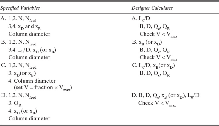
In design problems, the desired separation is set, and a column is designed that will achieve this separation. For binary distillation we would usually specify the mole fraction of the MVC in the distillate and bottoms products. In addition, the external reflux ratio, L0/D in Figure 3-8, is usually specified. Finally, we usually specify that the optimum feed location be used; that is, the feed location that will result in the fewest total number of stages. The designer’s job is to calculate distillate and bottoms flow rates, the heating and cooling requirements in the reboiler and condenser, the number of stages required and the optimum feed stage location, and finally the required column diameter. Alternative specifications such as the splits (fraction of a component recovered in the distillate or bottoms) or distillate or bottoms flow rates are common. Four sets of possibilities are summarized in Table 3-2.
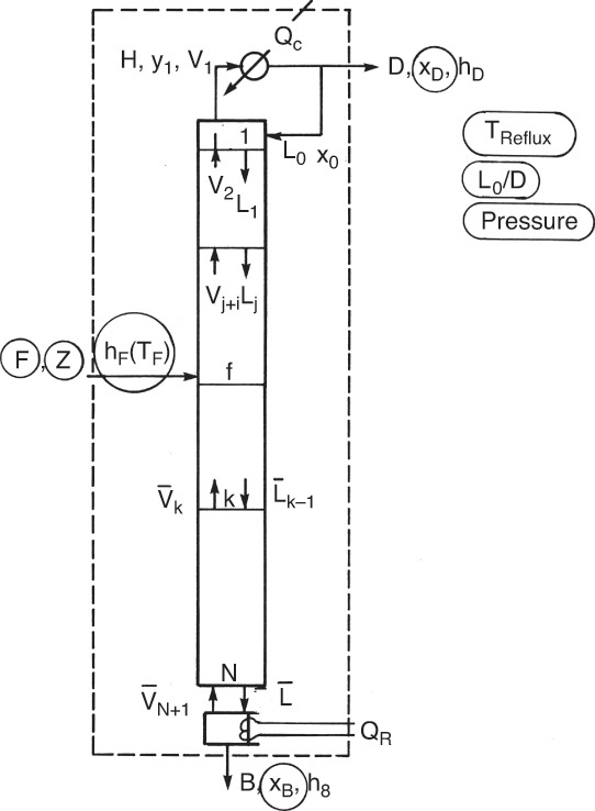
FIGURE 3-8. Binary distillation column: Circled variables are typically specified in design problems.
A. 1. Mole fraction MVC in distillate, xD
2. Mole fraction MVC in bottoms, xB
3. External reflux ratio, L0/D
4. Use optimum feed plate
B. 1,2. Fractional recoveries of components in distillate and bottoms, (FRA)dist, (FRB)bot
3. External reflux ratio, L0/D
4. Use optimum feed plate
C. 1. D or B
2. xD or xB
3. External reflux ratio, L0/D
4. Use optimum feed plate
D. 1,2. xD and xB
3. Boilup ratio, V/B
4. Use optimum feed plate
A. Distillate and bottoms flow rates, D and B
Heating and cooling loads, QR and Qc
Number of stages, N
Optimum feed plate, Nfeed
Column diameter
B. xB, xD, D, B
QR, Qc
N
Nfeed
Column diameter
C. B or D
xB or xD
QR, Qc
N and Nfeed
Column diameter
D. D and B, QR and Qc
N, Nfeed
Column diameter
TABLE 3-2. Specifications and calculated variables for binary distillation for design problems
In simulation problems, the column has already been built, and we wish to predict how much separation can be achieved for a given feed rate. Since the column has already been built, the number of stages and the feed stage location are already specified. In addition, the column diameter and the reboiler size, which usually control a maximum vapor flow rate, are set. There are a variety of ways to specify the remainder of the problem (see Table 3-3). The desired composition of MVC in the distillate and bottoms could be specified, and the engineer would then have to determine the external reflux ratio, L0/D, that will produce this separation and check that the maximum vapor flow rate will not be exceeded. An alternative is to specify L0/D and either distillate or bottoms composition, in which case the engineer determines the unknown composition and checks the vapor flow rate. Another alternative is to specify the heat load in the reboiler and the distillate or bottoms composition. The engineer would then determine the reflux ratio and unknown product composition and check the vapor flow rate. The thread that runs through all these alternatives is that since the column has been built, some method of specifying the separation must be used.
The engineer always specifies variables that can be controlled. Several sets of possible specifications and calculated variables are outlined in Tables 3-1 to 3-3. Study these tables to determine the difference between design-type and simulation-type problems. Note that other combinations of specifications are possible.
In Table 3-1 we find five specified variables common to both types of problems. For design problems (Table 3-2), four additional variables must be set. Note that whereas column diameter is a specified variable in simulation problem C, it serves as a constraint in simulation problems A, B, and D (Table 3-3). Column diameter will allow us to calculate Vmax, and then we can check that V < Vmax. However, we have not specified a variable for simulation. In problem C, where we specify V = fraction × Vmax, the column diameter serves as a variable for simulation.
Chapter 4 starts with the simple design problem and progresses to simulation and other, more complicated problems.
3.4 External Column Balances
Once the problem has been specified, the engineer must calculate the unknown variables. Often it is not necessary to solve the entire problem, since only limited answers are required. The first step is to do mass and energy balances around the entire column. For binary design problems, these balances can usually be solved without doing stage-by-stage calculations. Figure 3-8 shows the schematic of a distillation column. The specified variables for a typical design problem are circled. Since columns are normally insulated because it saves energy and for safety reasons (columns can be very hot or cold), we will assume that the column is well insulated and can be considered adiabatic. Column pressure is assumed to be constant.
From the balances around the entire column, we wish to calculate distillate and bottoms flow rates, D and B, and the heat loads in the condenser and reboiler, Qc and QR. We can start with mass balances around the entire column using the balance envelope shown by the dashed outline in the figure. The overall mass balance is
and the MVC mass balance is
For the design problem shown in Figure 3-8, Eqs. (3-1) and (3-2) can be solved immediately, since the only unknowns are B and D. Solving Eq. (3-1) for B, substituting this into Eq. (3-2), and solving for D, we obtain
and

Don’t memorize equations like these; they depend on the column geometry and can be derived as needed.
If fractional recoveries FRMVC,dist and FRLVC,bot are specified instead of product purities,
Equations (3-5a) and (3-5b) require that
Distillate and bottoms flow rates are calculated as
And the mole fractions are
Fractional recoveries are intensive variables that are closely related to mole fractions [see Problem 3.C2 and Eq. (3-17)].
For the energy balance we will use the convention that all heat loads will be treated as inputs. If energy is removed, then the numerical value of the heat load will be negative. The steady-state energy balance around the entire column is
where we have assumed that kinetic and potential energy and work terms are negligible. QR is positive and Qc negative. The enthalpies in Eq. (3-8) can all be determined from an enthalpy-composition diagram (e.g., Figure 2-4) or from heat capacities and latent heats of vaporization. In general,
These three enthalpies can all be determined. We would find hB on Figure 2-4 on the saturated liquid (boiling-line) at x = xB.
Since F was specified and D and B were just calculated, we are left with two unknowns, QR and Qc, in Eq. (3-8). Obviously another equation is required.
For the total condenser shown in Figure 3-8, we can determine Qc. The total condenser changes the phase of the entering vapor stream but does not affect the composition. The splitter after the condenser changes only flow rates. Thus composition is unchanged and
The condenser mass balance is
Since the external reflux ratio, L0/D, is specified, we can substitute its value into Eq. (3-10b):
Since the terms on the right-hand side of Eq. (3-10c) are known, we can calculate V1. The condenser energy balance is
Since stream V1 is a vapor leaving an equilibrium stage, it is a saturated vapor. Thus
and the enthalpy can be determined (e.g., on the saturated vapor [dew-line] of Figure 2-4 at y = y1). Since the reflux and distillate streams are at the same composition, temperature, and pressure, h0 = hD. Thus
Solving for Qc we have
or, substituting in Eq. (3-10c) and then Eq. (3-3),

Note that Qc < 0 because the liquid enthalpy, hD, is less than the vapor enthalpy, H1. This agrees with our convention. If the reflux is a saturated liquid, H1 – hD =λ, the latent heat of vaporization per mole. With Qc known we can solve the column energy balance, Eq. (3-8), for QR:
or
or

QR will be a positive number. Use of these equations is illustrated in Example 3-1.
EXAMPLE 3-1. External balances for binary distillation
A steady-state, countercurrent, staged distillation column is to be used to separate ethanol from water. The feed is a 30.0 wt% ethanol, 70.0 wt% water mixture at 40°C. Flow rate of feed is 10,000 kg/h. The column operates at a pressure of 1.0 kg/cm2. The reflux is returned as a saturated liquid. A reflux ratio of L/D = 3.0 is being used. We desire a bottoms composition of xB = 0.05 (weight fraction ethanol) and a distillate composition of xD = 0.80 (weight fraction ethanol). The system has a total condenser and a partial reboiler. Find D, B, Qc, and QR.
Solution
A. Define. The column and known information are sketched in the following figure.
Find D, B, Qc, and QR.

B. Explore. Since there are only two unknowns in the mass balances, B and D, we can solve for these variables immediately. Either solve Eqs. (3-1) and (3-2) simultaneously, or use Eqs. (3-3) and (3-4). For the energy balances, enthalpies must be determined. These can be read from the enthalpy-composition diagram (Figure 2-4). Then Qc can be determined from the balance around the condenser and QR from the overall energy balance.
C. Plan. Use Eqs. (3-3) and (3-4) to find D and B, Eq. (3-14b) to determine Qc, and Eq. (3-15a) to determine QR.
D. Do It. From Eq. (3-3),
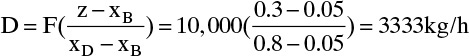
From Eq. (3-4), B = F – D = 10,000 – 3333 = 6667 kg/h
From Figure 2-4 the enthalpies are
hD(xD = 0.8, saturated liquid) = 60 kcal/kg
hB(xB = 0.05, saturated liquid) = 90 kcal/kg
hF(z = 0.3, 40°C) = 30 kcal/kg
H1(y1 = xD = 0.8, saturated vapor) = 330 kcal/kg
From Eq. (3-14b),
![]()
From Eq. (3-15a), QR = DhD + BhB – FhF – QC
QR = (3333)(60) + (6667)(90) – (10,000)(30) – (–3,599,640) = 4,099,650 kcal/h
E. Check. The overall balances, Eqs. (3-1) and (3-8), are satisfied. If we set up this problem on a spreadsheet, we obtain identical answers.
F. Generalize. In this case we could solve the mass and energy balances sequentially. This is not always the case. Sometimes the equations must be solved simultaneously (see Problem 3.D3). Also, the mass balances and energy balances derived in the text were for the specific case shown in Figure 3-8. When the column configuration is changed, the mass and energy balances change (see Problems 3.D2, 3.D3, and 3.D5). For binary distillation we can usually determine the external flows and energy requirements from the external balances. Exceptions are discussed in Chapter 4.
References
Biegler, L. T., I. E. Grossmann, and A. W. Westerberg, Systematic Methods of Chemical Process Design, Prentice Hall, Upper Saddle River, NJ, 1997.
Felder, R. M., and R. W. Rousseau, Elementary Principles of Chemical Processes, 3rd Updated ed., Wiley, New York, 2004.
Green, D. W., and R. H. Perry (Eds.), Perry’s Chemical Engineers’ Handbook, 8th ed., McGraw-Hill, New York, 2008.
Humphrey, J. L., and G. E. Keller II, Separation Process Technology, McGraw-Hill, New York, 1997.
Keller, G. E., II, “Separations: New Directions for an Old Field,” AIChE Monograph Series, 83 (17), 1987.
Luyben, W., Distillation Design & Control Using AspenTM Simulation, Wiley: New York, 2013.
Olujic, Z., “Vacuum and High-Pressure Distillation,” in Gorak, A. and Olujic, Z. (Eds.), Distillation Equipment and Processes, Chapter 9. Academic Press, London, 2014.
Homework
A. Discussion Problems
A1. Explain how a distillation column works.
A2. Without looking at the text, define the following:
a. Isothermal distillation
b. The four flow regimes in a staged distillation column
c. Reflux and reflux ratio
d. Boilup and boilup ratio
e. Rectifying (enriching) and stripping sections
f. Simulation and design problems
Check the text for definitions you did not know.
A3. Explain the reasons a constant pressure distillation column is preferable to
a. An isothermal distillation system.
b. A cascade of flash separators at constant temperature.
c. A cascade of flash separators at constant pressure.
A4. In a countercurrent distillation column at constant pressure, where is the temperature highest? Where is it lowest?
A5. Develop your own key relations chart for this chapter. In one page or less draw sketches, write equations, and include all key words you would want for solving problems.
A6. For a binary separation, is KMVCV/L usually less than, equal to, or greater than 1.0? For a binary separation, is KLVCV/L usually less than, equal to, or greater than 1.0?
A7. Specifications for a distillation column similar to Figure 3-8 cannot include all three flow rates F, D, and B. Why not?
A8. What are the purposes of reflux? How does it differ from recycle?
A9. In an abstract sense, is boilup a type of reflux?
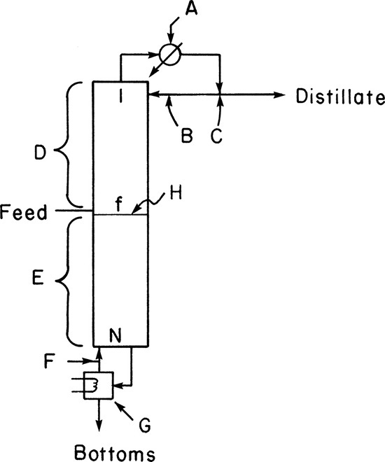
A10. Without looking at the text, name the labeled streams and column parts in the following figure.
B. Generation of Alternatives
B1. There are ways in which columns can be specified other than those listed in Tables 3-1 to 3-3.
a. Develop alternative specifications for design problems.
b. Develop alternative specifications for simulation problems.
C. Derivations
C1. For the column shown in Problem 3.D2, derive equations for D, B, Qc, and L/D.
C2. Show that for binary distillation in a column with a single feed, a total condenser, and a partial reboiler,

If the LVC in the bottoms is very pure, what is the limiting value of FRMVC,dist?
C3. Show that Eqs. (3-3) and (3-4) are valid for a column with two feeds (e.g., shown in Figure 4-18) as long as we define Ftotal = F1 + F2 and ztotal = (F1z1 + F2z2)/F.
C4. A partial condenser takes vapor leaving the top of a distillation column and condenses a portion of it. The vapor portion of mole fraction yD is removed as the distillate product. The liquid portion of mole fraction x0 is returned to the column as reflux. The liquid and vapor leaving the partial condenser can be assumed to be in equilibrium. Derive the mass and energy balances for a partial condenser.
D. Problems
*Answers to problems with an asterisk are at the back of the book.
D1. A distillation column with two feeds is separating ethanol from water. The first feed is 60.0 wt% ethanol, has a total flow rate of 1000.0 kg/h, and is a mix of liquid and vapor at 81°C. The second feed is 10.0 wt% ethanol, has a total flow rate of 500.0 kg/h, and is liquid at 20°C. Bottoms product is 0.01 wt% ethanol, and distillate product is 85.0 wt% ethanol. The column operates at 1.0 kg/cm2 and is adiabatic. The column has a partial reboiler, which acts as an equilibrium contact, and a total condenser. The distillate and reflux are saturated liquids. Find B and D in kg/h, and find Qc and QR in kcal/h. Use data in Figure 2-4.
a. External reflux ratio, Lo/D = 3.0 (mass units).
b. Boilup ratio, ![]() (mass units).
(mass units).
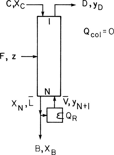
D2.* A distillation column separating ethanol from water is shown in the following figure. Pressure is 1.0 kg/cm2. Instead of having a reboiler, 100.0 kg/min of saturated steam (pure water vapor) is injected directly into the bottom of the column to provide heat. Feed rate is 100.0 kg/min of 30.0 wt% ethanol at 20°C. Reflux is a saturated liquid. Distillate concentration is 60.0 wt% ethanol, and bottoms product is 5.0 wt% ethanol. What is the external reflux ratio, L/D?

D3.* A distillation column separating ethanol from water is shown in the following figure. Pressure is 1.0 kg/cm2. Instead of having a condenser, a stream of pure liquid ethanol is added directly to the column to serve as the reflux. This stream is a saturated liquid. 2000.0 kg/h of feed at –20°C that is 40.0 wt% ethanol is added. Distillate concentration is 80.0 wt% ethanol, and bottoms composition is 5.0 wt% ethanol. A total reboiler is used, and the boilup is a saturated vapor. The cooling stream is input at C = 1000.0 kg/h. Find the external boilup rate, ![]() . Note: Set up the equations, solve in equation form for
. Note: Set up the equations, solve in equation form for ![]() , including explicit equations for all required terms, read off all required enthalpies from the enthalpy composition diagram (Figure 2-4), and then calculate a numerical answer.
, including explicit equations for all required terms, read off all required enthalpies from the enthalpy composition diagram (Figure 2-4), and then calculate a numerical answer.
D4. A partial condenser takes vapor leaving the top of a distillation column and condenses a portion of it. The vapor portion of mole fraction yD is removed as the distillate product. The liquid portion of mole fraction x0 is returned to the column as reflux. The liquid and vapor leaving the partial condenser can be assumed to be in equilibrium. A distillation column with a partial condenser and a partial reboiler is separating 100.0 kmol/h of saturated liquid feed that is 30.0 mol% methanol and 70.0 mol% water. Column pressure is 1.0 atm. We desire a 99.0% recovery of the methanol in the vapor distillate and a 98.0% recovery of water in the bottoms. Equilibrium data are in Table 2-7 (in Problem 2.D1), and other data are in Problem 3.E1.
a. Find D, B, yD,M, and xB,M.
b. If L/D = 2.0, find x0,M, flow rate L0 of the reflux stream, Qc, and QR.
D5.
a.* A distillation column is separating ethanol from water at a pressure of 1 kg/cm2. A two-phase feed of 20.0 wt% ethanol at 93°C is input at 100.0 kg/min. The column has a total condenser and a partial reboiler. The distillate composition is 90.0 wt% ethanol. Distillate and reflux are at 20°C. Bottoms composition is 1.0 wt% ethanol. Reflux ratio is L0/D = 3. A liquid side stream is withdrawn above the feed stage. Side stream is 70.0 wt% ethanol, and side stream flow rate is 10.0 kg/min. Find D, B, Qc, and QR. Data are in Figure 2-4.
b. Feed rate is increased to 250.0 kg/min, and side stream flow rate is unchanged. Repeat part a.
c. Feed rate is increased to 250.0 kg/min, and side stream flow rate is increased to 25.0 kg/min. Repeat part a.
D6.* A distillation column receives a feed that is 40 mol% n-pentane and 60 mol% n-hexane. Feed flow rate is 2500.0 lbmol/h, and feed temperature is 30°C. The column is at 1 atm. A distillate that is 99.9 mol% n-pentane is desired. A total condenser is used. Reflux is a saturated liquid. The external reflux ratio is L0/D = 3. Bottoms from the partial reboiler is 99.8 mol% n-hexane. Find D, B, QR, and Qc. Note: Watch your units on temperature.

where T is in °C and CPV and CPL are cal/(mol°C) or Btu/(lbmol°F).
Source for λ and CP data is Felder and Rousseau (2004).
D7. A continuous, steady-state distillation column is fed a mixture that is 70.0 mol% n-pentane and 30.0 mol% n-hexane. Feed rate is 1000.0 kmol/h. Feed is at 35°C. Column is at 101.3 kPa. The vapor distillate product is 99.9 mol% n-pentane and the bottoms product is 99.9 mol% n-hexane. The system has a partial condenser (thus the distillate product is a saturated vapor) and operates at an external reflux ratio of L/D = 2.8. The reboiler is a partial reboiler. Find D, B, Qc, and QR. Data are given in Problem 3.D6. Use the DePriester chart to determine boiling points.
D8. A partial condenser takes vapor leaving the top of a distillation column and condenses a portion of it. The vapor portion of mole fraction yD is the distillate product. The liquid portion of mole fraction x0 is returned to the column as reflux. The liquid and vapor leaving partial condensers and partial reboilers can be assumed to be in equilibrium. A distillation column with a partial condenser and a partial reboiler is separating 300.0 kmol/h of a saturated liquid feed that is 30.0 mol% ethanol and 70.0 mol% water. We obtain 98.0% recovery of ethanol in the vapor distillate and 81.0% recovery of water in bottoms. Pressure is 1.0 bar.
a. Find D, B, yD,M, and xB,M.
b. If L0/D = 2.0, find x0 and L0 where subscript 0 refers to the reflux stream. Also, find y1, the vapor mole fraction ethanol entering the partial condenser. Find Qc and QR.
a. We are distilling 2000.0 kg/h of a saturated vapor feed that is 45.0 wt% ethanol and 55.0 wt% water at a pressure of 1 kg/cm2. Bottoms product is 0.01 wt % ethanol, and vapor distillate from a partial condenser (see Problem 3.D8 for a description) is 88.0 wt% ethanol. Reflux ratio (in mass flow rates) is L0/D =2.9. Reflux is a saturated liquid. A vapor side stream with yside = 0.20 is withdrawn at a rate of 25.0 kg/h. Data are in Figure 2-4. Find D, B, QC, and QR.
b. If feed flow rate is doubled, find D, B, QC, and QR.
D10. A distillation column is separating 150.0 kmol/h of a saturated liquid mixture that is 30.0 mol% methanol and 70.0 mol% water. The column operates at 1.0 atm pressure. Reflux ratio is 2.0, and reflux is returned as a saturated liquid. We desire a 97.0% recovery of methanol in the distillate and a methanol distillate mole fraction of 0.990.
Find distillate flow rate D, bottoms flow rate B, methanol mole fraction in the bottoms xM,bot, and the fractional recovery of water in the bottoms.
D11. A distillation column with a partial condenser and a partial reboiler is separating methanol and water. Column pressure is 1.0 atm. We desire a bottoms product flow rate of 120.0 kmol/h that is 0.0001 mole fraction methanol. Boilup ratio is 1.5. Find QR.
D12. A rectifying or enriching column (see Figure 4-24B) receives 200.0 kmol/h of a feed that is 16.0 mol% ethanol and 84.0 mol% water. The feed is a saturated vapor. The column has a total condenser. We desire a bottoms product that is 3.0 mol% ethanol and a bottoms flow rate of B = 160.0 kmol/h. The column is at 1.0 atm, and the reflux is returned as a saturated liquid. Find D, xdist,E, L/V, and L/D.
D13. We are distilling 2000.0 kg/h of saturated liquid feed that is 45.0 wt% ethanol and 55.0 wt% water at a pressure of 1.0 kg/cm2. Bottoms product contains 0.01 wt % ethanol and vapor distillate (from a partial condenser) is 89.0 wt% ethanol. Reflux ratio (in mass flow rates) is L0/D =3.5. Reflux is a saturated liquid. Data are in Figure 2-4.
a. Find D, B, QC, and QR.
b. If the feed flow rate is doubled, find D, B, QC, and QR.
E. More Complex Problems
E1. 100.0 kmol/h of a 60.0 mol% methanol and 40.0 mol% water feed at 40°C is distilled in a column that does not have a reboiler but uses open steam for heating (see figure in Problem 3.D2). The column is at 1.0 atm. The steam is pure water vapor (yM = 0) and is a saturated vapor. The distillate product is 99.0 mol% methanol and is a saturated liquid. The bottoms is 2.0 mol% methanol and, since it leaves an equilibrium stage, must be a saturated liquid. The column is adiabatic and has a total condenser. External reflux ratio is L/D = 2.3.
Find D, B, Qc, and S. Be careful with units and in selecting basis for energy balance.
Data: λmethanol = ΔHvap = 8.43 kcal/mol = 35.27 kJ/mol (at boiling point)
λwater = ΔHvap = 9.72 kcal/mol = 40.656 kJ/mol (at boiling point)
Cp,w,liquid = 1.0 cal/(g °C) = 75.4 J/mol °C
CPL,Meoh = 75.86 + 0.1683T J/(mol °C)
Cp,w,vapor = 33.46 + 0.006880 T + 0.7604 × 10⁻⁵ T2 –3.593 × 10⁻⁹ T3
Cp,meoh,vapor = 42.93 + 0.08301 T – 1.87 × 10⁻⁵ T2 –8.03 × 10⁻⁹ T3
T is in °C, Cp,vapor values in J/mol °C
Sources: Felder and Rousseau (2004) and Green and Perry (2008).
VLE data: Table 2-7. Density and MW data Problem 2.D1.
E2. 500.0 kmol/h of a 60.0 mol% methanol–40.0 mol% water feed is separated in a distillation column with open steam (see figure in Problem 3.D2). Feed is a saturated liquid. The column is at 1.0 atm. The steam is pure water vapor (yM = 0) and is a saturated vapor. Distillate is 99.8 mol% methanol and leaves as a saturated liquid. The bottoms is 0.13 mol% methanol and is a saturated liquid. The column is adiabatic and has a total condenser. External reflux ratio is L/D = 3. Data are available in Problems 2.D1, 3.E1, and Table 2-7.
Find D, B, Qc, and S. Be careful with units and in selecting basis for energy balance.
F. Problems Requiring Other Resources
F1.* A mixture of oxygen and nitrogen is distilled at low temperature. The feed rate is 25,000 kmol/h and is 21.0 mol% oxygen and 79.0 mol% nitrogen. An ordinary column (Figure 3-8) is used. Column pressure is 1 atm. The feed is a superheated vapor at 100 K. Bottoms composition is 99.6 mol% oxygen, and distillate is 99.7 mol% nitrogen. Reflux ratio is L0/D = 4, and reflux is returned as a saturated liquid. Find D, B, QR, and Qc.
F2.* A mixture of water and ammonia is distilled in an ordinary distillation system (Figure 3-8) at a pressure of 6.0 kg/cm2. The feed is 30.0 wt% ammonia at 20°C. Distillate product is 98.0 wt% ammonia with a 95.0% recovery of ammonia in the distillate. The external reflux ratio is L0/D = 2.0. Reflux is returned at –20°C. Find D, B, xB, QR, and Qc per mole of feed.
G. Computer Simulation Problems (These two problems should be done after studying Lab 3 in Appendix A of Chapter 4.)
G1. Solve for Qc and QR in Problem 3.D1 with a process simulator.
a. Part a.
b. Part b.
Note: With Aspen Plus, use RADFRAC with an arbitrary (but large) number of stages and feed location = N/2. Do calculation for D by hand, and input correct values for D and L/D (or ![]() ).
).
G2. Solve Problem 3.D6 using a process simulator to find Qc and QR. To do this, do a hand calculation to find the value of D. Then arbitrarily set N = 40 and Nfeed = 20 in the process simulator and do the simulation.