
Chapter 14. Managing Paper Space Layouts
• Understand how and why paper space layouts are used
• Associate a printer/plotter with a layout
• Set the page size of a layout
• Create and import page setups
• Set the viewport display scale
• Control layer visibility per viewport
• Create and manage layouts
• Explore the paper space linetype scaling feature
Introduction
In Chapter 1, we explained how AutoCAD has two distinct drawing environments: model space and paper space.
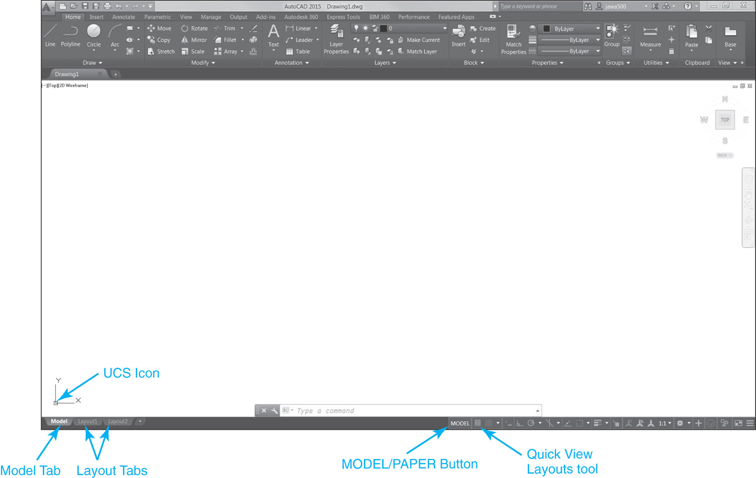
Remember that model space is the theoretically infinite 3D drawing environment where you locate most of the line work and annotation features that make up a drawing. To draw in model space, you select the Model tab at the bottom left of the drawing window as shown in Figure 14-1 to make it current.
Note
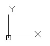
When model space is the active drawing environment, the UCS icon in the lower left-hand corner of the drawing window defaults to the icon shown in Figure 14-2.
To reiterate, paper space is the 2D environment where you lay out the drawing information created in model space for plotting/printing on the desired size of paper and at a specified scale factor. In effect, a layout represents what the drawing will look like when it is printed.
Tip
It is common to locate the title border information in a layout. Locating the border and title text in paper space allows them to be drawn at a scale of 1:1 because the plot scale in paper space is typically 1:1. Many of the default AutoCAD template files have the title border located in paper space.
It is possible to have multiple layouts in a drawing, each one a different paper size and scale. A new AutoCAD drawing that is based on the default template file (acad.dwt) contains two generic layouts named Layout1 and Layout2.
The quickest and easiest way to switch between layouts is to select the desired layout tab on the bottom left of the drawing window shown in Figure 14-1.
Note
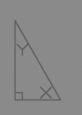
When paper space is the active drawing environment, the UCS icon in the lower left-hand corner of the drawing window defaults to the icon shown in Figure 14-3.
Layout Paper Size
The paper size used by an AutoCAD layout is controlled via its page setup, similar to setting the paper size of a document in a word processing program.
The difference is that, using AutoCAD, the available paper sizes are determined by the limits of the layout’s associated plotting/printing hardware device. For instance, if you are printing on a printer whose maximum paper size capability is 8½″ × 11″ (A-size/letter), then an 8½″ × 11″ paper size is the maximum size you can specify for the layout. Applying this logic, a large-format plotter that is capable of printing up to a 36″ × 24″ drawing (D-size) has many more paper size settings available than the average 8½″ × 11″ office printer. Associating a printer/plotter with a layout and selecting the desired paper size are both controlled using the Page Setup Manager explained later in this chapter.
Layout Viewport Scale
The scale of a drawing is controlled via one or more layout viewports created in a layout.
layout viewport: The user-defined window created in a paper space layout that allows you to view drawing information that resides in model space.
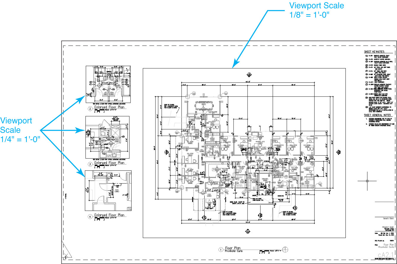
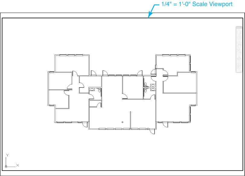
In Chapter 1 we used the analogy that an AutoCAD paper space layout can be thought of as a 2D sheet of paper that hovers over your 3D model space drawing information. Views of the model space information are created by cutting one or more holes referred to as layout viewports in the paper so that you can see the drawing model below. You scale the model space information displayed in the viewport by zooming in and out at a specific scale factor. It is even possible to create multiple viewports and specify a different scale factor for each individual viewport, as shown in Figure 14-4, allowing you to easily create multiscaled drawings.
Tip
AutoCAD provides a list of all of the standard viewport scales on the status bar so that you can quickly set a viewport scale without having to calculate the zoom scale factor each time. Both methods are described later in this chapter.
Being able to create plots with differently scaled viewports is one of the primary benefits of using paper space layouts. This is something you simply can’t do in model space unless you scale the actual drawing information—which should be avoided at all costs. Remember that in AutoCAD, the key is to draw everything exactly as it exists in the real world.
Controlling Layers per Layout Viewport
Another very useful capability of layout viewports is that you can freeze and thaw layers per viewport using the viewport layer freeze option introduced in Chapter 6. This allows you to create multiple viewports on one or more layouts that each display different model space drawing information.
You can also control the layer color, linetype, lineweight, transparency, and plot style properties per viewport using viewport layer overrides. Viewport layer overrides allow you to change the layer color, linetype, lineweight, transparency, and plot style properties in each viewport while retaining the original layer properties in model space and in the other layout viewports. Viewport layer overrides are discussed in detail later in this chapter.
For More Details
See Chapter 6 for more information about using layers to organize drawing information.
Setting Up a Layout
Once you are ready to lay out a drawing for plotting from paper space, select one of the default layouts (Layout1 or Layout2).
When you switch to a layout for the first time, a single layout viewport is displayed on the page with a dashed line indicating the printable area as shown in Figure 14-5.
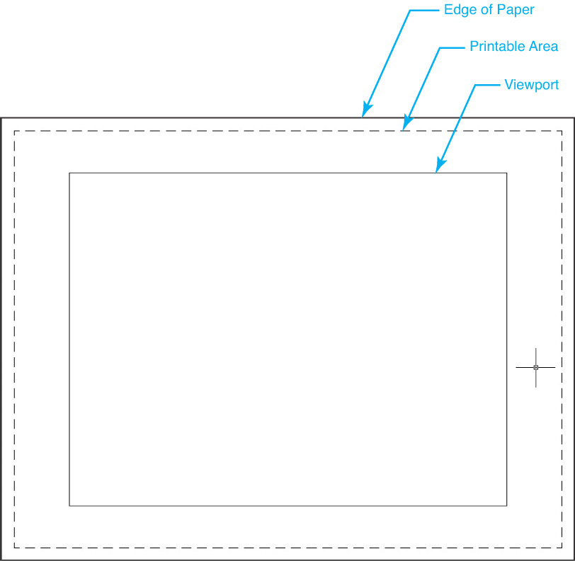
printable area: The actual physical area that can be printed for the currently specified plotting device and paper size.
The first thing you need to do when you are setting up a layout is to specify the desired printer/plotter output device. Once you specify an output device, then you can select a paper size. Remember that the two are intimately related because the available paper sizes are determined by the capabilities of the currently associated printer/plotter. The printer/plotter, paper size, and most of the other plot settings are controlled via the page setup associated with the layout.
Page Setup Manager |
|
Ribbon & Panel: |
Output | Plot
|
Menu: |
File | Page Setup Manager... |
Command Line: |
PAGESETUP |
Command Alias: |
None |

To modify the settings for the page setup, you use the Page Setup Manager, which is explained in the next section.
The Page Setup Manager
The Page Setup Manager allows you to do the following:
• Display details of the current page setup
• Set another page setup current
• Modify an existing page setup
• Create a new page setup
• Import a page setup from another drawing
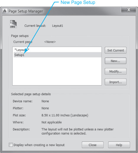
The Page Setup Manager dialog box is shown in Figure 14-6.
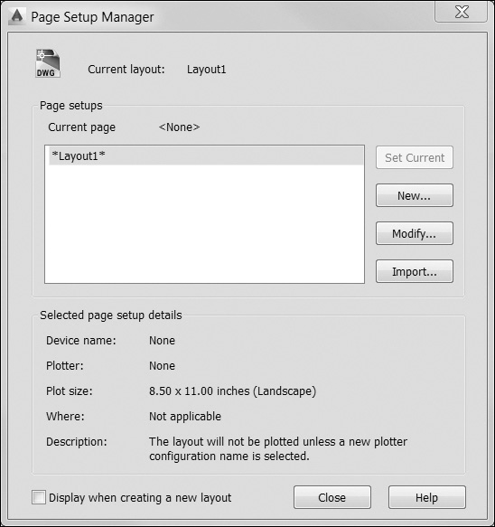
Current page displays the page setup that is applied to the current layout. By default it is set to <None>.
The Page setups box lists the page setups that can be modified or applied to the current layout.
By default, a page setup is automatically applied to each layout with the same name as the layout with an asterisk (*) added to the beginning and end of the layout name. For instance, the default page setups for the Layout1 and Layout2 layouts are *Layout1* and *Layout2*, respectively.
Any new or imported page setups are automatically added to the Page setups list. You can make a page setup current by double-clicking on it in the list or by highlighting the page setup and selecting the Set Current button.
Tip
If you right-click in the Page setups list box, a shortcut menu is displayed that allows you to set current, rename, or delete a page setup.
Note
It is not possible to set current, rename, or delete any of the default page setups that begin and end with an asterisk.
The Selected page setup details area at the bottom of the dialog box displays the following information about the currently selected page setup:
• Device name Name of the plot device specified in the currently selected page setup
• Plotter Type of plot device specified in the currently selected page setup
• Plot size Plot size and orientation specified in the currently selected page setup
• Where Physical location of the output device specified in the currently selected page setup
• Description Description of the output device specified in the currently selected page setup
The Display when creating a new layout check box allows you to control whether the Page Setup Manager is displayed when a new layout tab is selected or a new layout is created.
Tip
You can also control whether the Page Setup Manager is displayed for new layouts via the Show Page Setup Manager for new layouts option on the Display tab of the Options dialog box.
Modifying a Page Setup
You can modify the settings of a page setup at any time. In order to modify any default page setup, the layout the page setup is associated with must first be set current. Selecting the Modify... button in the Page Setup Manager dialog box displays the Page Setup dialog box shown in Figure 14-7.
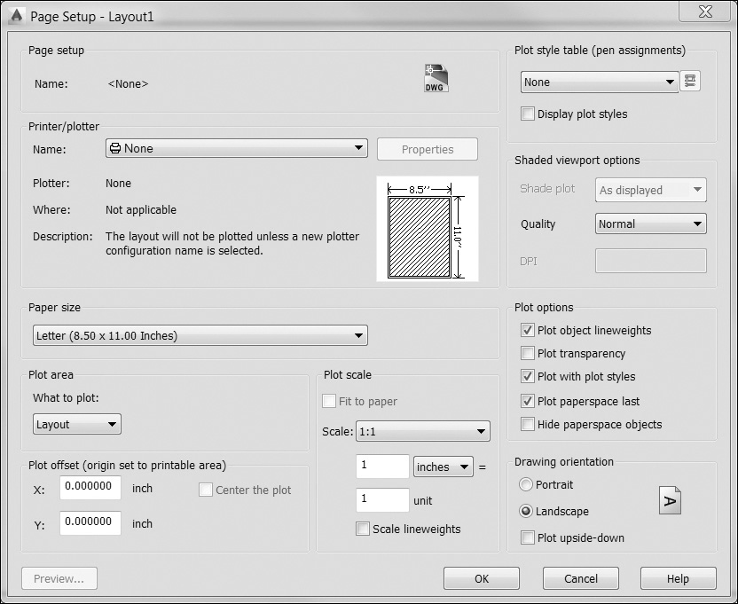
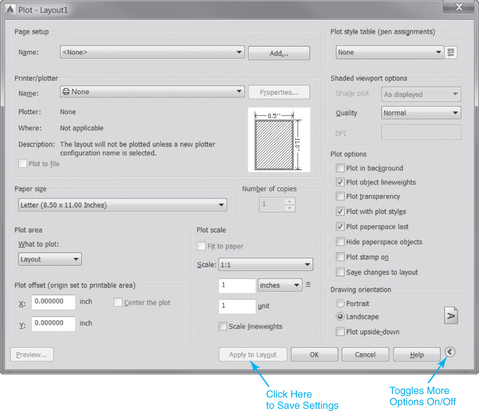
The Page Setup dialog box is almost exactly the same as the Plot dialog box shown in Figure 14-8. In fact, the two dialog boxes control the same settings. The only differences between the two are:
• Changes made in the Page Setup dialog box are saved with the layout. Changes made in the Plot dialog box are not saved, unless you select the Apply to Layout button.
• You can plot from the Plot dialog box. You cannot plot from the Page Setup dialog box.
• The Plot dialog box can be toggled to display more plot options using the More Options arrow button at the bottom right of the dialog box as shown in Figure 14-8, or it can be set to display a limited number of options.
In this chapter, the main concern is controlling the paper size of the layout so that you can properly set up a drawing for plotting (discussed in Chapter 15). For this reason, most of the other plot-related page setup settings are mentioned only briefly. The following sections explain primarily how to associate an output device so that you can select the desired layout paper size.
Selecting a Printer/Plotter Device
The Printer/plotter area of the Page Setup dialog box allows you to specify a printer/plotter by selecting it from the Name: list box shown in Figure 14-9.
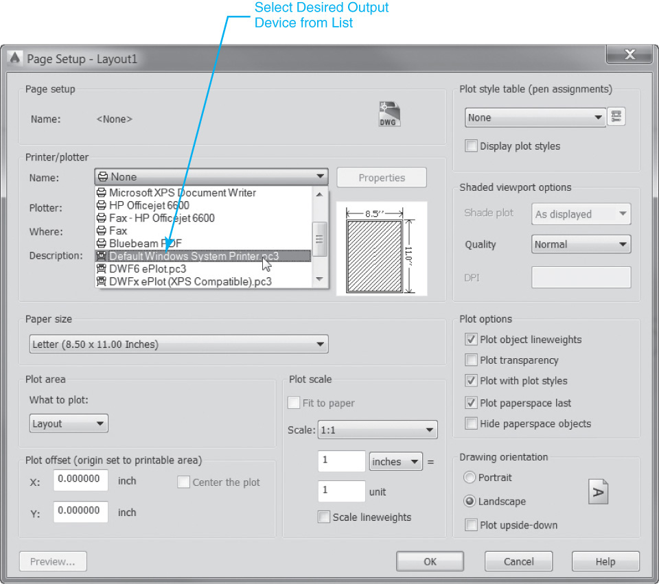
The Name: list box provides a list of the available printers/plotters you can associate with a layout. The list includes both .PC3 files and system printers that are prefixed with different icons—a plotter icon for a .PC3 file and a printer icon for a system printer.
.PC3 file: Plotter configuration file used to store and manage printer/plotter settings.
The Properties button displays the Plotter Configuration Editor so you can view or modify the current plotter configuration.
For More Details
See page 628 in Chapter 15 for more on using the Plotter Configuration Editor to manage .PC3 files.
Other information provided about the currently selected printer/plotter includes the following:
• Plotter Displays the current name
• Where Displays the physical location or port
• Description Displays a description if available
The Preview window displays the plot area relative to the paper size and the printable area.
Note
If the printer/plotter you wish to use is not listed, you can add it using the Plotter Manager’s Add-a-Plotter wizard.
Selecting a Paper Size
The Paper size list box displays the standard paper sizes that are available for the associated printer/plotter. Every time a different printer/plotter is selected, the Paper size list is updated with the paper sizes supported by that device. If no plotter is selected so that the Name: list box is set to None, a list of all the standard paper sizes is provided.
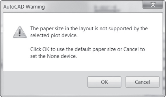
Note
If the selected printer/plotter doesn’t support the current paper size, the warning shown in Figure 14-10 is displayed. If you select OK, the paper size is changed to the default paper size for the new printer/plotter. If you select Cancel, the printer/plotter is changed to None, and the paper size is not changed.
If you are plotting a raster image, such as a BMP or TIFF file, the size of the plot is specified in pixels, not in inches or millimeters.
Tip
If you are unsure what printer/plotter to specify, you can set the plotter to None so that it is still possible to select the desired paper size.
Other Page Setup Settings
The following is a brief overview of a few of the other page setup settings.
The Plot area settings determine the area of the drawing to plot. The What to plot: list box provides five different options:
• Display The current screen display
• Extents The extents of the drawing
• Layout The current layout
• View A named view (must have at least one named view to be enabled)
• Window User-specified window area
The Plot area is typically set to Layout for a paper space layout. The other Plot area settings are more commonly used when plotting in model space.
The Plot offset area allows you to offset the plot area relative to the lower-left corner of the printable area or the edge of the paper.
Note
You can change what the offset is relative to via the Specify plot offset relative to options on the Plot and Publish tab of the Options dialog box.
For More Details
See Chapter 15 for more detailed information about controlling the other plot settings and plotting your drawing.
The Plot scale area controls the ratio of the plotted units to the drawing units. Most of the standard drafting scales are listed in the Scale: list box. The default scale is 1:1 when plotting a layout.
Creating a New Page Setup
If you think that you might use the same page setup settings in another layout in the current drawing or even in a layout in another drawing, you can create a named page setup. Named page setups are saved in the drawing file so that they can be applied to other layouts or imported into other drawing files. Importing page setups is explained in the next section.
Using named page setups also allows you to plot the same layout more than one way. You can apply different named page setups to the same layout so that there are different output results each time. For example, you might create different named page setups to plot to printers/plotters that are in different locations.
To create a new named page setup, select the New... button in the Page Setup Manager dialog box. The New Page Setup dialog box shown in Figure 14-11 is displayed.
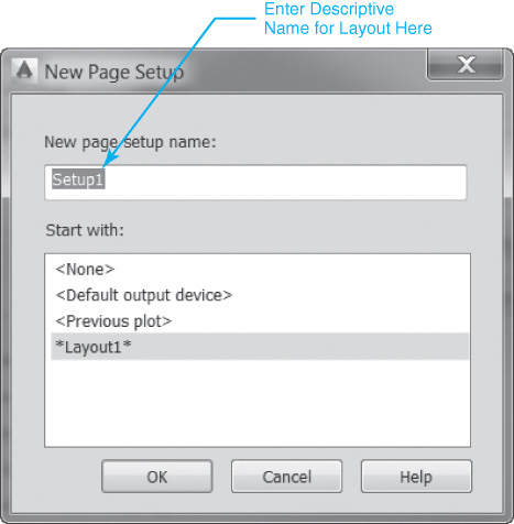
Enter the name for the new page setup in the New page setup name: text box. The default name is Setup followed by an integer representing a sequential number (i.e., Setup1, Setup2). You should enter a descriptive name indicating the page setup’s purpose.
The Start with: list allows you to select a page setup to use as a starting point for the new page setup:
• <None> No page setup is used as a starting point.
• <Default output device> The default output device specified on the Plot and Publish tab of the Options dialog box is set as the printer in the new page setup.
• <Previous plot> The new page setup uses the settings specified in the last plot.
When you select the OK button at the bottom of the New Page Setup dialog box, the Page Setup dialog box shown earlier in Figure 14-7 is displayed using the settings saved with the selected starting point page setup. You can then modify any settings if necessary. When you exit the Page Setup dialog box, the new named page setup is displayed in the list of page setups in the Page Setup Manager as shown in Figure 14-12.
Importing a Page Setup from Another Drawing
A named page setup can be imported from another drawing file (DWG), drawing template file (DWT), or designexchange format file (DXF). To import a named page setup, select the Import... button in the Page Setup Manager shown in Figure 14-6. The Select Page Setup from File dialog box is displayed so that you can select the source file from which you want to import. After you locate the file and select the Open button, the Import Page Setups dialog box shown in Figure 14-13 is displayed so you can select one or more page setups.
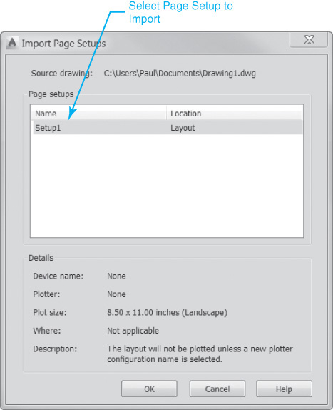
The Page setups list box lists the page setups that can be imported from the selected drawing and whether they are located in model space or paper space. The Name column lists the name of the page setup, and the Location column lists the page setup location (model or layout).
Note
If a page setup with the name selected already exists in the drawing, a warning is displayed asking you whether you want to redefine it. Selecting OK overwrites the page setup with the new page setup settings.
The Details area at the bottom of the dialog box displays information about the selected page setup.
• Device name The name of the plot device specified in the currently selected page setup
• Plotter The type of plot device specified in the currently selected page setup
• Plot size The plot size and orientation specified in the currently selected page setup
• Where Physical location of the output device specified in the currently selected page setup
• Description Description of the output device specified in the currently selected page setup
Select OK to import the selected page setup.
Setting a Page Setup Current
The Set Current button on the Page Setup Manager dialog box sets the selected page setup current for the active layout so that all the page setup settings are updated to match the selected page setup.
Exercise 14-1 Using the Page Setup Manager
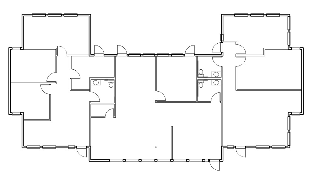
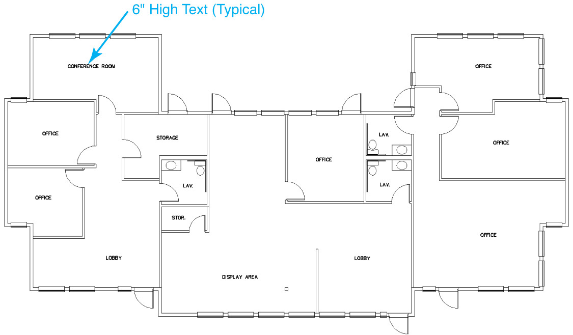
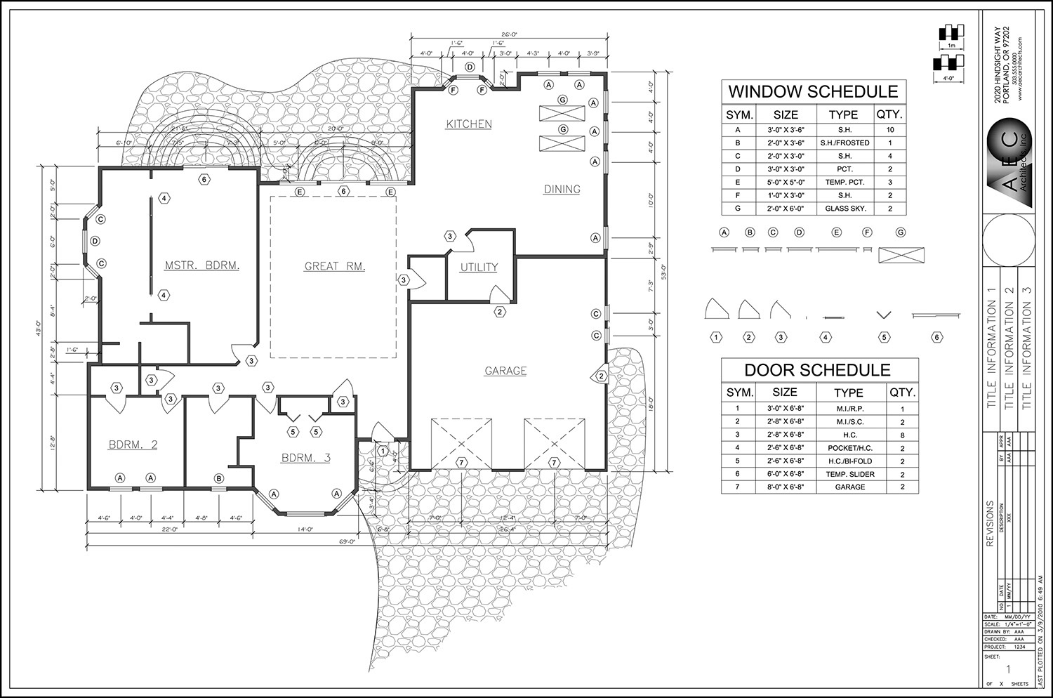
![]() Open the building floor plan drawing named EX14-1 in the student data files to display the building floor plan shown in Figure 14-14.
Open the building floor plan drawing named EX14-1 in the student data files to display the building floor plan shown in Figure 14-14.
To access student data files, go to www.pearsondesigncentral.com.
![]() Select the Layout1 tab so that paper space is active and Layout1 is the current layout.
Select the Layout1 tab so that paper space is active and Layout1 is the current layout.
![]() Use the Page Setup Manager to set the associated plotter to None and the paper size to ARCH D (36.00 × 24.00 Inches).
Use the Page Setup Manager to set the associated plotter to None and the paper size to ARCH D (36.00 × 24.00 Inches).
![]() Select the Layout2 tab, and switch to the Layout2 layout.
Select the Layout2 tab, and switch to the Layout2 layout.
![]() Use the Page Setup Manager to set the associated plotter to None and the paper size to ANSI B (17.00 × 11.00 Inches).
Use the Page Setup Manager to set the associated plotter to None and the paper size to ANSI B (17.00 × 11.00 Inches).
![]() Save the drawing as CH14_EXERCISE.
Save the drawing as CH14_EXERCISE.
Creating Layout Viewports
Layout viewports are the windows that you create in paper space that allow you to view the drawing information in model space at a specified scale (refer to Figure 14-4). Just like the windows in a building, layout viewports can be many different shapes and sizes. A layout viewport can be rectangular, polygonal, or even circular! You can create a single viewport that fits the paper size of the layout, or you can create multiple viewports. Each viewport is controlled independently so that different model space information can be displayed in each viewport, even at different scales if necessary.
Note
Do not attempt to create one layout viewport completely within the borders of another layout viewport because unpredictable results can occur. It is possible, though, to overlap viewports.
A layout viewport is treated just like other basic AutoCAD drawing objects such as lines, circles, and arcs. Similar to drawing other AutoCAD objects, a new viewport assumes the current object properties such as layer, color, and linetype when it is created.
After a viewport is created, you can modify it using any of the standard modify commands (ERASE, MOVE, COPY, SCALE, etc.). You can even use grips to resize a viewport quickly using the STRETCH option.
Tip
Typically, you do not want viewports to be displayed on the final plotted drawing. Because of this, layout viewports should be created on a unique layer so that you can control their visibility. The best approach is to create layout viewports on a layer whose Plot property is set to No plot so that you can see the viewports in the AutoCAD drawing window, but they do not plot.
You can create one or more layout viewports using the MVIEW, -VPORTS, or VPORTS command. Creating layout viewports using each of these commands is explained in the following sections.
Creating a Single Rectangular Viewport
The most common type of layout viewport is a single rectangular viewport. A single rectangular viewport is created by selecting two corner points. It is the default viewport option when you use either the MVIEW or -VPORTS command.
Single Viewport |
|
Ribbon & Panel: |
Layout | Layout Viewports |
|
|
Menu: |
Views | Viewports | 1 Viewport |
Command Line: |
MVIEW VPORTS -VPORTS |
Command Alias: |
MV |
Tip
Do not forget to create a unique viewport layer set to No plot and make it current before you create a viewport using the MVIEW or -VPORTS command. Some typical layer names used include Viewport or Vport.
When you start either command, AutoCAD prompts you to Specify corner of viewport or ![]() as shown in Figure 14-15.
as shown in Figure 14-15.
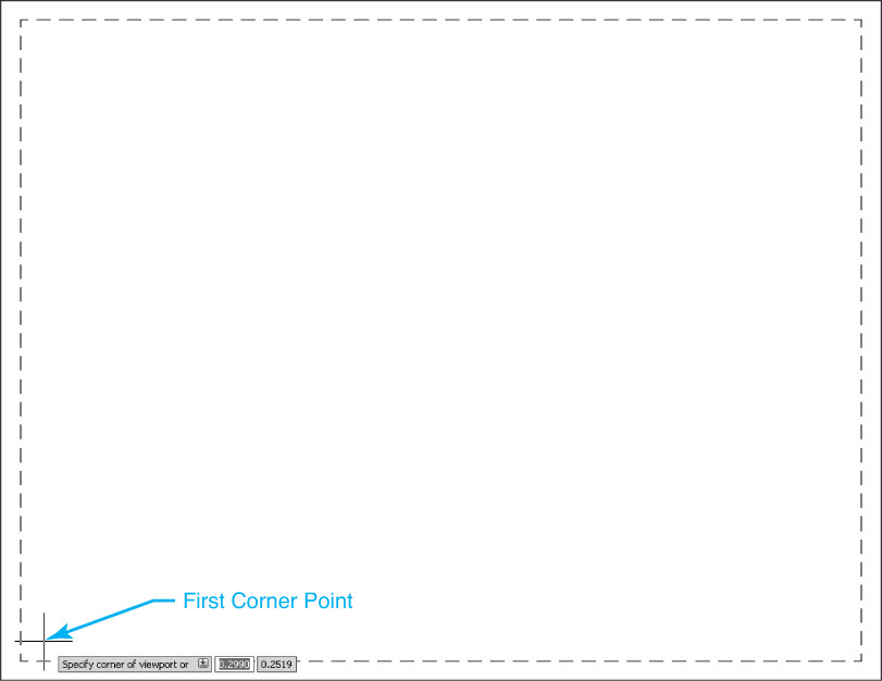
Select the first corner of the viewport or enter a coordinate value at the keyboard. AutoCAD then prompts you to Specify opposite corner: as shown in Figure 14-16 so you can specify the second point.
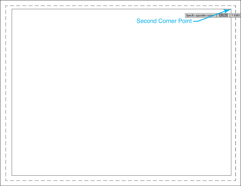
The viewport is immediately zoomed to the extents of the model space drawing information as shown in Figure 14-17.
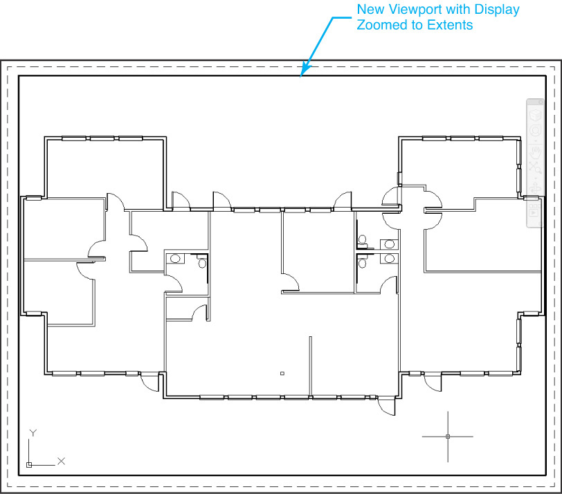
At this point, the viewport is not set at any standard scale. You must manually set the viewport scale factor using the techniques explained later in this chapter.
Tip
You can create a rectangular viewport that is the exact size of the layout’s printable area using the Fit option. Fit is the default option so that you can simply press the <Enter> key when you run either the MVIEW or -VPORTS command before specifying the first viewport corner point.
Creating a Polygonal Viewport
You can create an irregularly shaped viewport with three or more sides using the Polygonal option of the MVIEW or -VPORTS command. A polygonal viewport is created by selecting multiple points.
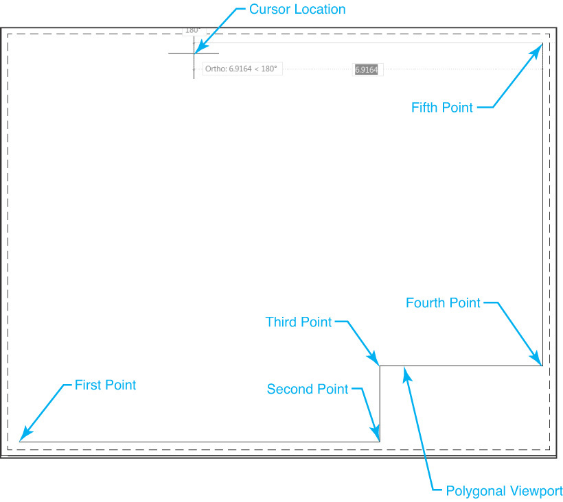
To create a polygonal viewport, start the MVIEW or -VPORTS command and select the Polygonal option. AutoCAD prompts you to Specify start point:. After selecting the first point, AutoCAD prompts you to Specify next point or ![]() so you can start selecting points and define the viewport polygon as shown in Figure 14-18.
so you can start selecting points and define the viewport polygon as shown in Figure 14-18.
Polygonal Viewport |
|
Ribbon & Panel: |
Layout | Layout Viewports
|
Menu: |
Views | Viewports | Polygonal Viewport |
Command Line: |
MVIEW VPORTS |
Command Alias: |
MV |

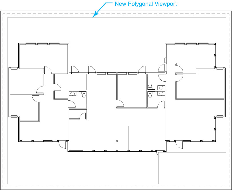
To finish the polygon viewport, you close it by selecting the Close option. The Close option draws a viewport segment from the last current point to the start point and exits the command. Similar to a rectangular viewport, a polygonal viewport is immediately zoomed to the extents of the model space drawing information as shown in Figure 14-19.
Tip
You can also press <Enter> to close a polygonal viewport after three or more viewport points have been defined.
The Arc option allows you to create arc segments when you are defining a polygonal viewport. You can pick a second point to define the arc, or you can select from a number of arc suboptions. The arc creation suboptions are the same as those used with the PLINE command.
For More Details
See page 350 in Chapter 9 for more detailed information about using the PLINE command Arc options.
The Length option creates a viewport segment a specified length at the same angle as the previous segment. If the previous viewport segment is an arc, the new segment is drawn tangent to that arc segment.
Object |
|
Ribbon & Panel: |
Layout | Layout Viewports
|
Menu: |
Views | Viewports | Object |
Command Line: |
MVIEW, VPORTS |
Command Alias: |
MV |

The Undo option will undo the most recent viewport segment.
Converting an Object into a Viewport
You can convert any of the following objects into a layout viewport:
• Polyline
• Circle
• Ellipse
• Region
• Spline
In order to convert a polyline into a viewport, the polyline must be closed, and it must have more than three vertices.
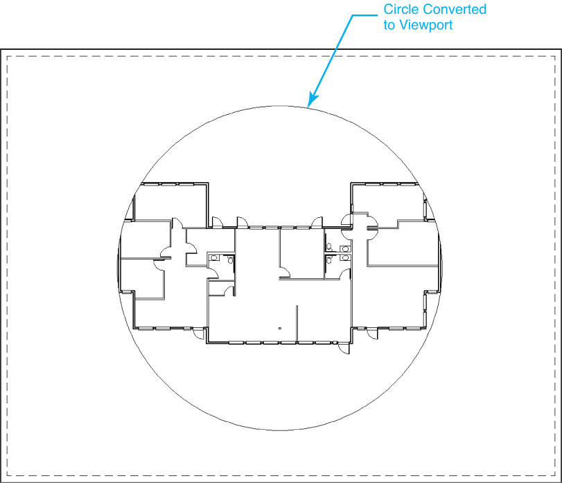
To convert an object into a layout viewport, start the MVIEW or -VPORTS command, and select the Object option. AutoCAD prompts you to Select object to clip viewport: so you can pick the object to convert. A circle is shown converted to a viewport in Figure 14-20.
New Viewport |
|
Ribbon & Panel: |
Layout | Layout Viewports |
|
|
Menu: |
Views | Viewports | New Viewports... |
Command Line: |
VPORTS |
Command Alias: |
None |
Using the Viewports Dialog Box
You can automatically create one or more rectangular viewports using the Viewports dialog box. The VPORTS command displays the Viewports dialog box shown in Figure 14-21.
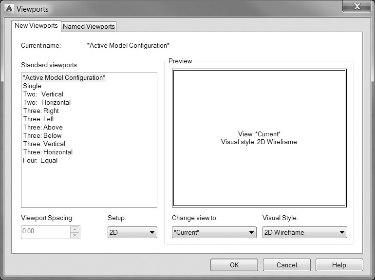
The Standard viewports: box on the left displays a list of standard viewport configurations that you can select. The Preview window displays a preview of the selected viewport configuration.
The Viewport Spacing: box allows you to specify the spacing you want to apply between the viewports for the selected configuration. The Preview window is updated to show the results of the spacing indicated.
The Setup: list box allows you to switch between a 2D and a 3D viewport setup. When you select 3D, standard orthogonal 3D views are applied to the selected viewport configuration. The Change view to: list box replaces the view in the selected viewport with the view you select from the list. The Visual Style: list box allows you to change the visual style used for the viewport. It should typically be set to 2D Wireframe, unless you are working in 3D.
Select OK after you have specified the desired configuration and spacing to exit the Viewports dialog box. After the dialog box is closed, AutoCAD asks you to specify the rectangular area within which to fit the viewport configuration by prompting you to pick two corner points.
You can use the Fit option to make the viewport configuration fill the layout’s printable area by pressing the <Enter> key when AutoCAD prompts for the first corner point.
Exercise 14-2 Creating Layout Viewports
![]() Continue from Exercise 14-1.
Continue from Exercise 14-1.
![]() Select the Layout1 tab so that paper space is active and Layout1 is the current layout.
Select the Layout1 tab so that paper space is active and Layout1 is the current layout.
![]() Create a new layer named Viewport, set its Plot property to No plot, and make it the current layer.
Create a new layer named Viewport, set its Plot property to No plot, and make it the current layer.
![]() Create a rectangular viewport using the MVIEW or -VPORTS command that is the same size as the printable area. Hint: The Fit option creates a viewport the same size as the printable area.
Create a rectangular viewport using the MVIEW or -VPORTS command that is the same size as the printable area. Hint: The Fit option creates a viewport the same size as the printable area.
![]() Select the Layout2 tab and switch to the Layout2 layout.
Select the Layout2 tab and switch to the Layout2 layout.
![]() Create a rectangular viewport using the MVIEW or -VPORTS command that is the same size as the printable area.
Create a rectangular viewport using the MVIEW or -VPORTS command that is the same size as the printable area.
![]() Save the drawing.
Save the drawing.
Note
Double-clicking with your mouse directly on the viewport border maximizes the viewport so it fills the entire drawing window. You can double-click on the maximized border to return to the regular layout view. Maximizing viewports is covered later in this chapter.
Making a Viewport Current
There are three ways to make a layout viewport current:
• Select the PAPER button on the status bar.
• Enter the MSPACE or MS command.
• Double-click with your mouse inside a viewport.
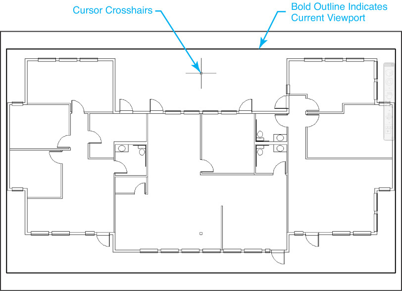
The first two methods work best when you are working with a single layout viewport. If you have more than one viewport, you must double-click with your mouse inside the viewport you want to make current. When a viewport is current, its borderline becomes bold, and your mouse pointer changes to the cursor crosshairs mode as shown in Figure 14-22.
When a viewport is current, you can work on the model space drawing just like you are in model space—although it can be somewhat cumbersome working “through” the viewport. The ability to maximize viewports, which is discussed later in the chapter, makes this process much more user-friendly.
Switching Back to Paper Space
There are three ways to switch back to paper space so that no viewports are current:
• Select the MODEL button on the status bar.
• Enter the PSPACE or PS command.
• Double-click with your mouse outside all viewports.
All information that is created when paper space is active and no viewports are current is added to paper space exclusively (TILEMODE = 0). In this mode, it is possible to add information (such as titles and drawing scales) directly above a viewport. This approach allows you to add information to your drawing that is displayed on the plotted drawing but does not need to be part of the model space design.
Setting the Viewport Scale
As explained earlier in the chapter, the scale of the drawing information displayed in a layout viewport is controlled by zooming in on and out of the active viewport. If you zoom in, the drawing gets larger, and the scale is increased. If you zoom out, the drawing gets smaller, and the scale is decreased. To set a viewport to a standard drafting scale, you must zoom in on or out of the viewport at a zoom scale factor equal to the scale you want the drawing information to plot. For instance, if you want the drawing information in a viewport to plot at a scale of 2:1, you must zoom in by a scale factor of 2 in the viewport so that everything appears twice as large as actual size. To plot at a scale of 1:2, you zoom out by a scale factor of 1/2 so that everything is half of its actual size.
Zooming in on and out of a layout viewport to a specific scale factor is done using the XP option of the ZOOM command.
The X in the XP option represents a multiplication sign, and the P stands for paper space. The number preceding the XP is the value the view is scaled relative to the paper space scale, which is 1:1. For example, to create a viewport that is scaled at 2:1, you would enter 2XP in response to the ZOOM command. In order to create a view that is scaled 1:2, you would enter 1/2XP or .5XP.
Using the ZOOM command with the XP option to set the viewport scale is fine when you are working with simple scales such as 2:1 or 1:2. Converting standard drafting scales such as 1/4″ = 1′-0″ or 1–12″ = 1′-0″ to their equivalent scale factors takes a little more time and effort. Luckily, AutoCAD provides some easier ways to set a viewport’s scale, which are explained in the following sections.
Setting the Viewport Scale on the Status Bar
The easiest way to set the viewport scale is via the Viewport Scale button on the right side of the AutoCAD status bar. Clicking anywhere on the Viewport Scale button displays a list of standard drafting scales that you can use to set the zoom scale factor of the current viewport as shown in Figure 14-23.
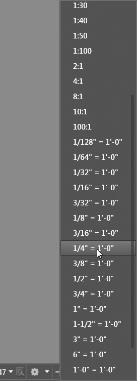
The viewport scale is displayed on the status bar only when a viewport is current. You can make a viewport current by double-clicking in the viewport with your mouse. Select the desired scale factor from the list, and the viewport is zoomed in or out by the preestablished scale factor.
Tip
After the viewport scale is set, zooming in and out using any Zoom tools should be avoided. Any incremental zoom is enough to change the zoom scale factor so that it is no longer correct. Panning the display is not a problem because the zoom factor remains the same. The easiest way to prevent inadvertent zooms is to lock the viewport by selecting the Lock/Unlock Viewport button to the left of the Viewport Scale button on the status bar when the viewport is current and toggling it so the Lock icon is closed.
Using the Properties Palette to Set the Viewport Scale
You can also control the viewport scale factor via the Properties palette. Setting the viewport scale using the Properties palette requires that you be in paper space in order to select the viewport object. Selecting a viewport displays the properties shown in Figure 14-24 so that you can select a Standard scale from the list.
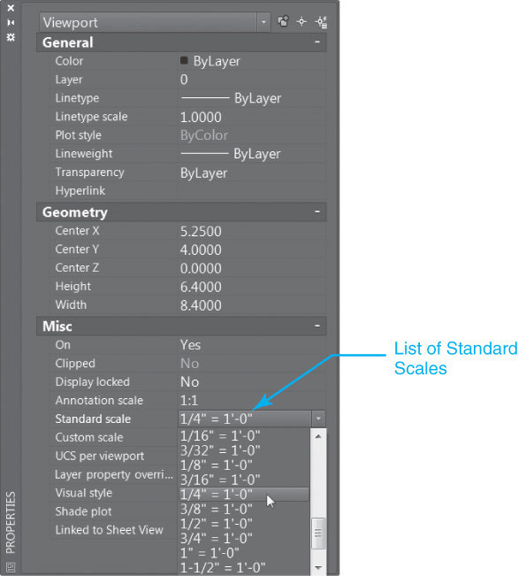
Tip
You can also set a custom scale using the Properties palette if the scale you need is not in the Standard scale list. To specify a custom scale, enter the desired scale factor in the Custom scale property text field.
Adding and Editing Scales in the Standard Scale List
The SCALELISTEDIT command allows you to add new scales or edit existing scales that appear in the Scale List box. You can either type in the command, or you can select Custom... from the bottom of the scale list. The Edit Drawing Scales dialog box shown in Figure 14-25 is displayed.
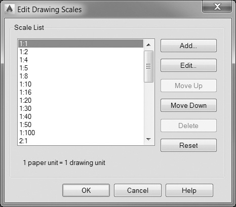
The Scale List on the left displays the list of currently defined scales. Selecting a scale from the list displays the ratio of paper units to drawing units at the bottom of the Scale List.
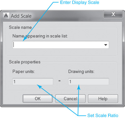
The Add... button allows you to add a custom scale to the list via the Add Scale dialog box shown in Figure 14-26. In this dialog box:
• The Scale name area is where you enter the descriptive or numeric name as you want it to appear in the list in the Name appearing in scale list text box.
• The Scale properties area is where you set the ratio of paper units to drawing units by entering the numeric values in the Paper units: and Drawing units: text boxes.
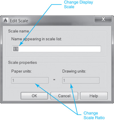
The Edit... button in the Edit Drawing Scales dialog box allows you to edit an existing scale via the Edit Scale dialog box shown in Figure 14-27. In this dialog box:
• The Scale name area is where you update the descriptive or numeric name as you want it to appear in the list in the Name appearing in scale list text box.
• The Scale properties area is where you change the ratio of paper units to drawing units by entering new numeric values in the Paper units: and Drawing units: text boxes.
The Move Up button in the Edit Drawing Scales dialog box moves the currently selected scale in the Scale List up one position so that it appears in that position in all scale list boxes. The Move Down button moves the currently selected scale in the Scale List down one position so that it appears in that position in all scale list boxes.
The Delete button permanently removes the currently selected scale from the Scale List. The Reset button deletes any custom scales that were added and restores the default list of standard AutoCAD scales.
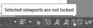
Locking the Viewport Display
You can protect the viewport scale from being accidentally changed by locking the viewport display so it is impossible to zoom or pan inside the viewport when it is current. When a viewport is locked, any attempt to zoom or pan affects the entire paper space layout similarly to if you were working in paper space. The current viewport remains active; it is just temporarily disabled during the zoom or pan process. The easiest way to lock a viewport is to select the Lock/Unlock Viewport button on the status bar as shown in Figure 14-28. In addition, you can also use the following methods:
• Select Lock or Unlock from the drop-down menu on the Layout Viewports panel on the Layout tab of the ribbon.
• Select viewport and right-click to display the shortcut menu and set the Display locked menu item to Yes.
• Set the Display locked property to Yes via the Properties palette.
• Use the MVIEW command’s Lock option and select the viewport.
To unlock a viewport, select the Lock/Unlock Viewport button or use any of the options listed above and set the Locked property to Off or No.
Exercise 14-3 Setting the Viewport Scale
![]() Continue from Exercise 14-2.
Continue from Exercise 14-2.
![]() Select the Layout1 tab so that paper space is active and Layout1 is the current layout.
Select the Layout1 tab so that paper space is active and Layout1 is the current layout.
![]() Make the viewport created in Exercise 14-2 the active viewport, and Zoom Extents so that the entire floor plan fills the viewport.
Make the viewport created in Exercise 14-2 the active viewport, and Zoom Extents so that the entire floor plan fills the viewport.
![]() Set the viewport scale to 1/4″ = 1′-0″ by selecting it from the Viewport Scale list on the right side of the status bar.
Set the viewport scale to 1/4″ = 1′-0″ by selecting it from the Viewport Scale list on the right side of the status bar.
![]() Select the Lock/Unlock Viewport button to the left of the Viewport Scale list to lock the viewport.
Select the Lock/Unlock Viewport button to the left of the Viewport Scale list to lock the viewport.
![]() Make paper space the active drawing environment by selecting the MODEL button on the status bar and toggling it to PAPER.
Make paper space the active drawing environment by selecting the MODEL button on the status bar and toggling it to PAPER.
![]() Layout1 should now look similar to Figure 14-29. It now is 1/4″ = 1′-0″ scale drawing on a D-size sheet (36″ × 24″).
Layout1 should now look similar to Figure 14-29. It now is 1/4″ = 1′-0″ scale drawing on a D-size sheet (36″ × 24″).
![]() Select the Layout2 tab, and switch to the Layout2 layout.
Select the Layout2 tab, and switch to the Layout2 layout.
![]() Make the viewport created in Exercise 14-2 the active viewport, and Zoom Extents so that the entire floor plan fills the viewport.
Make the viewport created in Exercise 14-2 the active viewport, and Zoom Extents so that the entire floor plan fills the viewport.
![]() Set the viewport scale to 1/8″ = 1′-0″ by selecting it from the Viewport Scale list on the right side of the status bar.
Set the viewport scale to 1/8″ = 1′-0″ by selecting it from the Viewport Scale list on the right side of the status bar.
![]() Select the Lock/Unlock Viewport button to the left of the Viewport Scale list to lock the viewport.
Select the Lock/Unlock Viewport button to the left of the Viewport Scale list to lock the viewport.
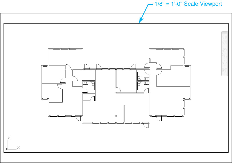
![]() Layout2 should now look similar to Figure 14-30. It is now a 1/8″ = 1′-0″ scale drawing on a B-size sheet (17″ × 11″).
Layout2 should now look similar to Figure 14-30. It is now a 1/8″ = 1′-0″ scale drawing on a B-size sheet (17″ × 11″).
![]() Make paper space the active drawing environment by selecting the MODEL button on the status bar and toggling it to PAPER.
Make paper space the active drawing environment by selecting the MODEL button on the status bar and toggling it to PAPER.
![]() Save the drawing.
Save the drawing.
Controlling Layers per Layout Viewport
As mentioned earlier, it is possible to control layers per layout viewport so that you can display different model space drawing information in each individual viewport while not affecting the information in model space. You can freeze and thaw layers in individual viewports, as well as control the color, linetype, lineweight, and transparency level used. These individual viewport specific layer settings are referred to as viewport layer overrides.
The most popular viewport layer override is the ability to freeze a layer in an individual viewport. This allows you to leave all of the layers on (thawed) in model space but then freeze different layers in each viewport to create multiple views of the same model space information and create different drawings. For example, one layout could be used to display the electrical plan information, and another layout might display only the HVAC plan information. The possibilities are endless, especially when combined with the concept of external reference drawings.
For More Details
See Chapter 17 for more information about using external reference drawings (xrefs).
There are two different ways to freeze layers per viewport: in the current viewport or in any new viewports. Freezing layers in the New VP Freeze column means that any information on the selected layers will not be displayed when you create any new layout viewports in the future.
Freezing layers in the current viewport is most common. Obviously, to freeze layers in the current viewport, you must first make the viewport current. After the viewport is current, start the LAYER command to display the Layer Properties Manager.
The viewport layer override columns are displayed at the right before the Description column as shown in Figure 14-31.
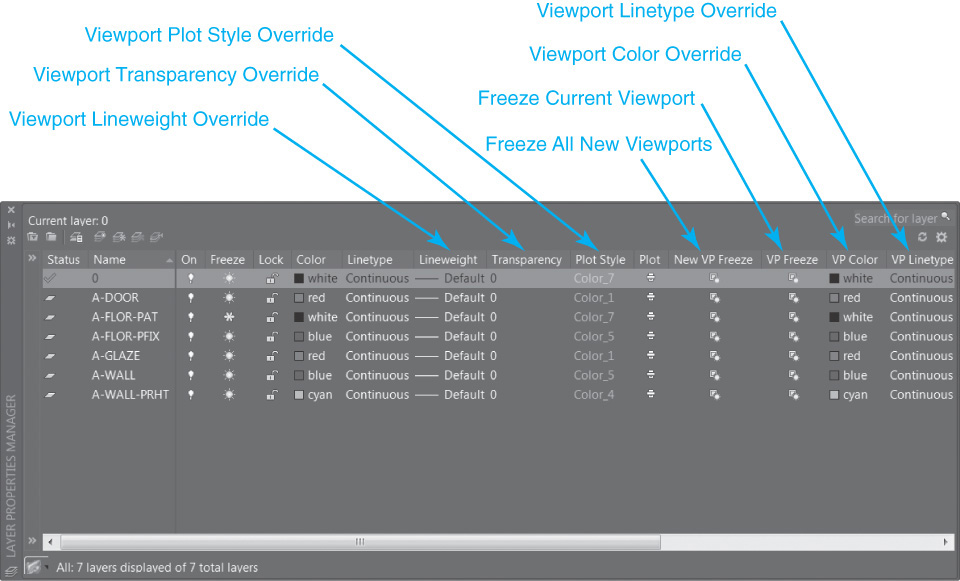
To freeze a layer in the current viewport, click on the sun icon in the VP Freeze column, and change it to a snowflake icon, just as with the regular Freeze option. The selected layer is frozen in the current viewport as shown in Figure 14-32.
Note
When any viewport layer override is applied, a different background color is used in the Layer Properties Manager.
The same technique can be used to override the other layer settings (color, linetype, lineweight, transparency, and plot style). Simply make the viewport current and select the desired overrides.
You can remove viewport layer overrides using the right-click menu in the Layer list in the Layer Properties Manager. The VPLAYEROVERRIDESMODE system variable allows you to temporarily turn off all viewport layer overrides.
Tip
When a viewport contains layer overrides, a Viewport Overrides property filter is automatically created so that you can select the Viewport Overrides filter and view only the layers that contain overrides.
For More Details
See Chapter 6 for more detailed information about layers and controlling the different layer properties using the Layer Properties Manager.
Modifying Layout Viewports
Because they are treated just like most other AutoCAD objects, layout viewports can be modified using most of the same modify commands you are already familiar with. You can move or copy viewports using the MOVE and COPY commands, just as you can scale and stretch viewports via the SCALE and STRETCH commands. Probably the most important is the ability to delete viewports using the ERASE command.
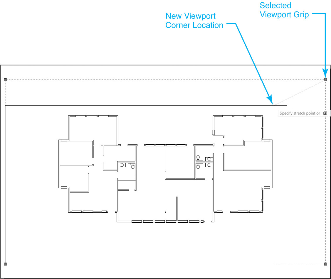
Resizing Viewports Using Grips
One of the most common ways to resize a viewport is to simply rely on grips. Using a viewport’s grips and the Stretch option allows you to modify a viewport quickly and make it the size needed as shown in Figure 14-33.
Viewport Clip |
|
Ribbon & Panel: |
Layout | Layout Viewports |
|
|
Pull-down Menu: |
None |
Command Line: |
VPCLIP |
Command Alias: |
None |
Clipping Viewports
You can change the shape of a viewport using the VPCLIP command.
Using the VPCLIP command, you can either select a different object to convert into a viewport, or you can redefine the viewport using a new polygon viewport.
Note
It is possible to convert circles, closed polylines, ellipses, closed splines, and regions into a layout viewport.
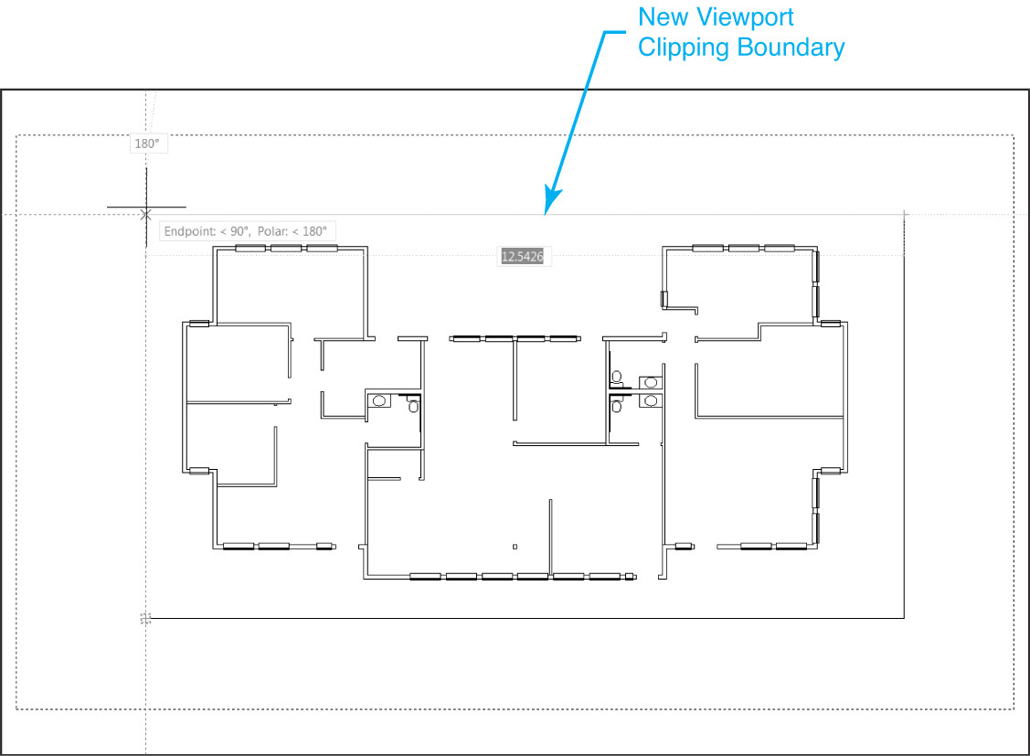
When you start the VPCLIP command and a viewport is not already selected, AutoCAD prompts you to Select viewport to clip: so you can select a viewport. Once a viewport is selected, AutoCAD prompts you to Select clipping object or ![]() . You can either select an object to convert into a viewport, or you can define a new polygon window by selecting the Polygon option. The options for creating a polygon viewport are the same as explained earlier in the chapter. The new viewport that is created to replace the existing viewport is referred to as a clipping boundary, as shown in Figure 14-34.
. You can either select an object to convert into a viewport, or you can define a new polygon window by selecting the Polygon option. The options for creating a polygon viewport are the same as explained earlier in the chapter. The new viewport that is created to replace the existing viewport is referred to as a clipping boundary, as shown in Figure 14-34.
The Delete option deletes the clipping boundary of a selected viewport. The Delete option is available only if the selected viewport has already been clipped once using the VPCLIP command.
Tip
You can determine whether a viewport has been clipped using the VPCLIP command by checking the viewport’s Clipped property via the Properties palette. If it is set to Yes, the viewport has been clipped.
Turning Viewport Display Off and On
You can turn the viewport display on and off temporarily so that the model space objects displayed in the viewport are no longer visible. This can be used to either speed up drawing regeneration time or control what drawing information is plotted. There are three ways to turn a viewport off:
• Select the viewport, right-click to display the shortcut menu, and set the Display Viewport Objects menu item to No.
• Set the viewport’s On property to No via the Properties palette.
• Use the MVIEW command’s Off option and select the viewport.
Note
The viewport boundary is still displayed if a viewport is turned off. Only the model space information is turned off.
A viewport that has been turned off is considered inactive. You can only have up to 64 viewports active at one time.
To make a viewport active again, use any of the options listed above to toggle the viewport’s Display property to On or Yes.
Tip
The maximum number of active viewports is controlled using the MAXACTVP system variable. The maximum value is 64.
Maximizing a Viewport
You can maximize a layout viewport so that it fills the entire drawing window area, which makes it easier to work on your model space design without switching entirely from paper space to model space. This feature was introduced to get around the complications of working “through” a layout viewport to get to the model space drawing information while you were still in paper space. There are four ways to maximize a layout viewport:
• Select the Maximize Viewport button on the status bar.
• Double-click on the viewport outline.
• Select the viewport, right-click to display the shortcut menu, and select the Maximize Viewport menu item.
• Type VPMAX<Enter>.
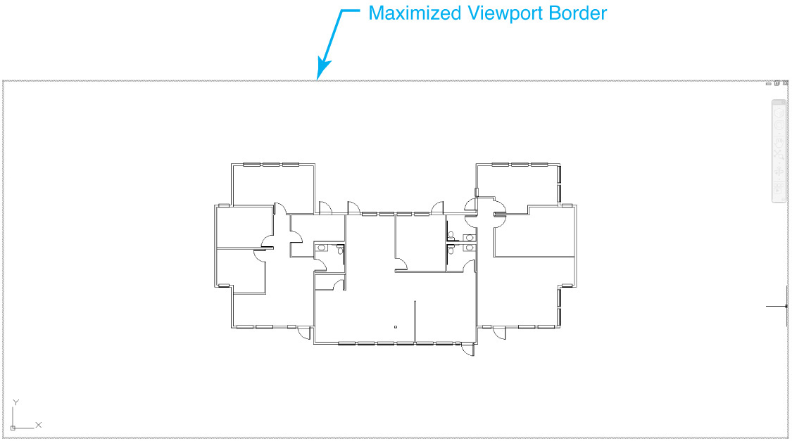
Any method enlarges the viewport to fit the drawing window display area and changes the border to a thick red hashed line (see Figure 14-35).
To pan and zoom when a viewport is maximized and not change the original viewport display when you switch back to the viewport, use the Minimize Viewport options below. When a viewport is maximized, it is almost as though you were working in model space on the Model tab.
There are four ways to restore the maximized layout viewport back to its original size and display:
• Select the Minimize Viewport button on the status bar.
• Double-click on the maximized viewport.
• Select the viewport, right-click to display the shortcut menu, and select the Minimize Viewport menu item.
• Type VPMIN<Enter>.
Exercise 14-4 Working with Multiple Annotation Scales
![]() Continue from Exercise 14-3.
Continue from Exercise 14-3.
![]() Create a text style named Notes with the following settings:
Create a text style named Notes with the following settings:
a. Font = Simplex.shx AutoCAD font
b. Annotative should be checked
c. Paper text height = 0.125″

![]() Select the Model tab so that model space is active.
Select the Model tab so that model space is active.
![]() Set the Notes text style current on the Annotation panel.
Set the Notes text style current on the Annotation panel.
![]() Set the A-Anno-Note layer current in the Layer list box.
Set the A-Anno-Note layer current in the Layer list box.
![]() Set the annotation scale to 1/8″ = 1′-0″ by selecting it from the Annotation Scale list on the status bar.
Set the annotation scale to 1/8″ = 1′-0″ by selecting it from the Annotation Scale list on the status bar.
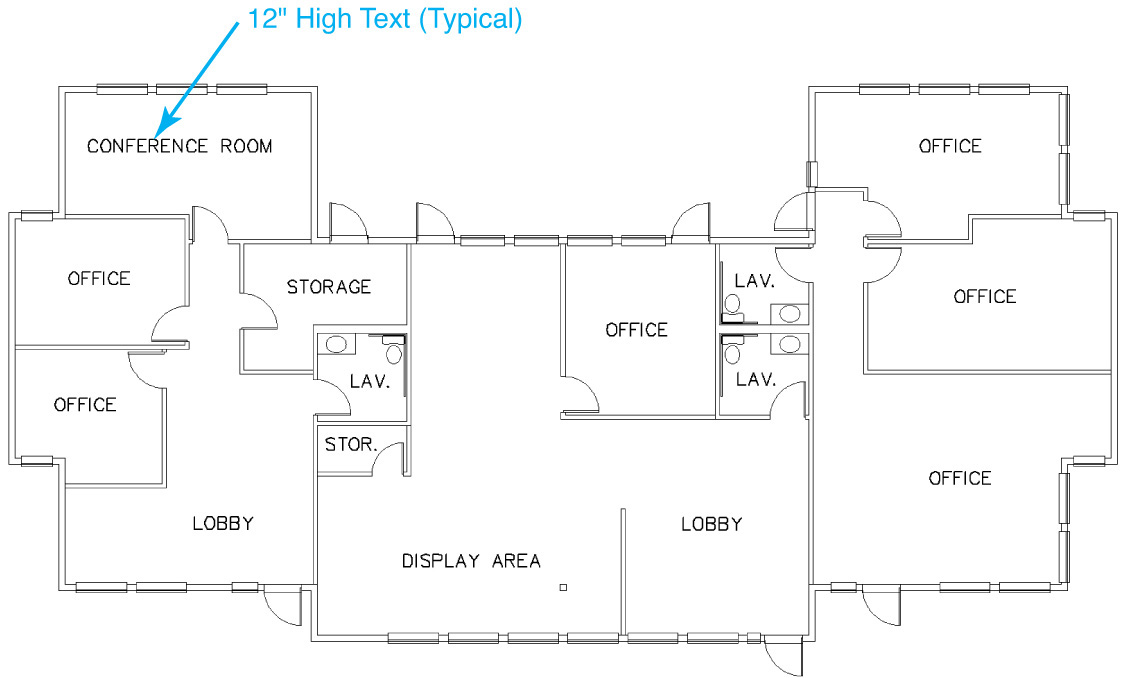
![]() Create the text shown in Figure 14-36 using the Center justification option.
Create the text shown in Figure 14-36 using the Center justification option.
![]() Select the Add scales to annotative objects when the annotation scale changes icon on the left of the Annotation Scale button on the status bar so it is on.
Select the Add scales to annotative objects when the annotation scale changes icon on the left of the Annotation Scale button on the status bar so it is on.
![]() Set the annotation scale to 1/4″ = 1′-0″ by selecting it from the list on the status bar. All text in the drawing should scale down by 1/2.
Set the annotation scale to 1/4″ = 1′-0″ by selecting it from the list on the status bar. All text in the drawing should scale down by 1/2.
![]() Center the 1/4″ = 1′-0″ text in each room by using the upper left grip to move each piece of text individually of its 1/8″ = 1′-0″ scale representation as shown in Figure 14-37.
Center the 1/4″ = 1′-0″ text in each room by using the upper left grip to move each piece of text individually of its 1/8″ = 1′-0″ scale representation as shown in Figure 14-37.
![]() Select the Layout1 tab so that paper space is active and Layout1 is the current layout. Only the 1/4″ = 1′-0″ text is visible.
Select the Layout1 tab so that paper space is active and Layout1 is the current layout. Only the 1/4″ = 1′-0″ text is visible.
![]() Select the Layout2 tab, and switch to the Layout2 layout. Only the 1/8″ = 1′-0″ text is visible.
Select the Layout2 tab, and switch to the Layout2 layout. Only the 1/8″ = 1′-0″ text is visible.
![]() Make paper space the active drawing environment by double-clicking outside the viewport.
Make paper space the active drawing environment by double-clicking outside the viewport.
![]() Save the drawing.
Save the drawing.
Managing Layouts
The following sections describe how to manage layouts so that you can do the following:
• Create a new layout
• Rename a layout
• Move or copy a layout
• Delete a layout
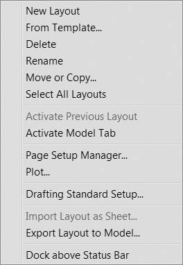
One of the easiest ways to accomplish any of these tasks is to rely on the layout’s right-click shortcut menu. Right-clicking with your mouse on any layout tab displays the shortcut menu shown in Figure 14-38.
Tip
The Select All Layouts menu item on the Layout right-click menu provides a quick way to perform a task on all the layouts at one time.
New Layout |
|
Ribbon & Panel: |
None
|
Menu: |
Insert | Layout | Layout from Template |
Command Line: |
LAYOUT |
Command Alias: |
LO |

The LAYOUT command also provides most of the same functionality, but as you might expect, it’s not quite as user-friendly. Emphasis is placed on using the right-click menu where appropriate in the following sections.
Creating a New Layout
There are four ways to create a new layout:
• Add a new generic layout tab with the default settings so that the settings must be updated via the Page Setup Manager.
• Import a layout from an existing drawing file (DWG), drawing template file (DWT), or design exchange format file (DXF).
• Use the Create Layout wizard that steps you through the layout setup.
• Copy an existing layout tab in the current drawing file and rename it.
The first three methods are described in the following sections. Copying a layout is covered a little later.
Adding a Generic Layout with Default Settings
You can quickly add a generic layout with default page setup settings. You must then use the Page Setup Manager described earlier in this chapter to set up the layout as required.

You can add a generic layout by selecting the Layout tab on the right with the plus “+” icon, by right-clicking and selecting New Layout from the shortcut menu, or by using the New option of the LAYOUT command.
AutoCAD prompts you to Enter new Layout name <Layout3>: if you add a new layout via the Insert menu or the LAYOUT command. The default layout name is “Layout” followed by an integer representing the layout number in the sequence.
When you select New Layout from the right-click shortcut menu, a layout is added with the default name, and you must rename it. Renaming layouts is covered later in this chapter.
Importing a Layout from a Drawing Template
To save time and effort, you can import a layout that is already set up with the correct paper size and plot settings from an existing drawing file (DWG), drawing template file (DWT), or designexchange format file (DXF).
Layout From Template |
|
Ribbon & Panel: |
None
|
Menu: |
Insert | Layout | Layout from Template |
Command Line: |
LAYOUT |
Command Alias: |
LO |

You can import a layout by selecting Layout from Template... from the Layout cascade menu on the Insert menu, by right-clicking and selecting From template... from the shortcut menu, or by using the Template option of the LAYOUT command.
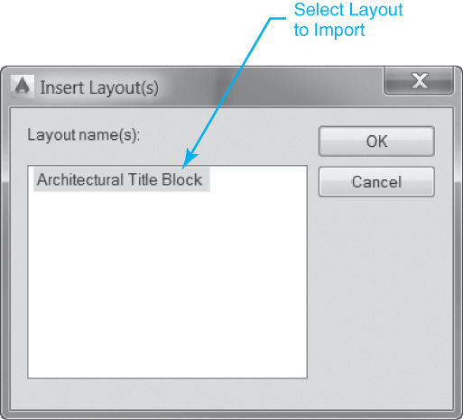
AutoCAD displays the Select Template From File standard file dialog box so you can select the file from which you want to import the layout. Selecting the Open button gets a list of the layouts in the selected file and displays them in the Insert Layout(s) dialog box shown in Figure 14-39.
If a layout with the same name already exists in the current drawing during the import process, the layout is still added, but it is renamed by prefixing the layout name with a default layout name and a dash (-).
Select one or more layouts you want to import in the Layout name(s): list box and select OK. The selected layout(s) are imported with all their settings and drawing information and added to the right end of the layout tabs at the bottom of the drawing window.
Create Layout Wizard |
|
Ribbon & Panel: |
None |
Menu: |
Insert | Layout | Create Layout Wizard |
Command Line: |
LAYOUTWIZARD |
Command Alias: |
None |
Creating a New Layout Using the Layout Wizard
The Create Layout wizard automates the process of creating, and setting up, a new layout by prompting you for information about the different layout settings in a series of preprogrammed steps.
You can start the Create Layout wizard by selecting Create Layout Wizard from the Layout cascade menu on the Insert menu or by using the LAYOUTWIZARD command. The Create Layout dialog box is displayed with the Begin step displayed as shown in Figure 14-40.
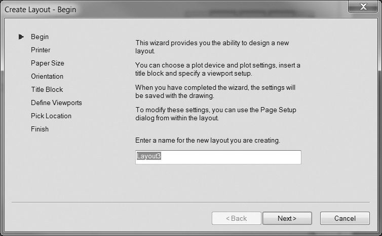
The steps that the wizard will take you through are listed on the left in sequence from top to bottom with the arrow to the left indicating the current step. Select the Next button to continue to the next step or the Back button to return to a previous step if you want to verify or change anything. The setup steps and options are as follows:
• Begin Allows you to enter the desired name for the new layout
• Printer Allows you to select a system printer/plotter output device
• Paper Size Allows you to specify a paper size based on the printer selected in the previous step and switch drawing units between millimeters and inches
• Orientation Allows you to switch between the portrait and landscape paper orientation modes
• Title Block Allows you to insert a predefined title block in the layout as a block or an xref. The title block drawings listed are located in the default AutoCAD Template folder
For More Details
See Chapter 16 for more information about blocks. See Chapter 17 for more information about external references (xrefs).
• Define Viewports Allows you to select a layout viewport configuration and set the viewport scale from a list of predefined standard scales
• Pick Location Allows you to define the area to fill with the viewport configuration selected in the previous step by picking two corner points. If no location is selected, AutoCAD uses the layout’s printable area
• Finish Exits the Create Layout wizard and creates the new layout with the selected settings
Note
You can always change the information entered in the Create Layout wizard later by selecting the layout and using the Page Setup Manager explained earlier in the chapter.
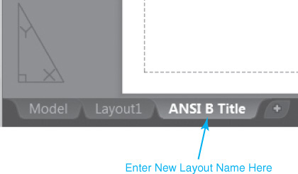
Renaming a Layout
The easiest way to rename a layout is to right-click on the layout tab and select Rename from the shortcut menu. You can then update the layout name directly on the layout tab as shown in Figure 14-41.
You can also rename a layout using the Rename option of the LAYOUT command. Using the LAYOUT command requires that you enter the layout to change in response to Enter layout to rename <Layout1>: where the current layout is the default name. AutoCAD then prompts you to Enter new layout name: so you can enter the new name.
Tip
You can double-click on a layout tab to automatically rename a layout.
Moving or Copying a Layout
The easiest way to move or copy a layout is to right-click on the layout tab and select Move or Copy... from the shortcut menu to display the Move or Copy dialog box shown in Figure 14-42.
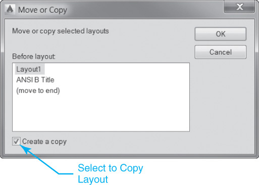
Select the layout from the list in the Before layout: list box that you want to locate the current layout before. When you select OK, the layout will be moved or copied so it appears as the layout tab directly preceding, or to the left of, the selected tab.
If you want to make a copy of a layout and move it at the same time, select the Create a copy check box on the bottom of the dialog box. AutoCAD creates a copy of the layout with the same name as the current layout with a numerical suffix representing the sequence appended in parentheses. For instance, Layout1 becomes Layout1(2).
Tip
It is possible to select a layout tab and drag it into another position with your mouse.
Deleting a Layout
The easiest way to delete a layout is to right-click on the layout tab and select Delete from the shortcut menu. AutoCAD displays a warning before deleting the layout so you can cancel the operation or select OK to continue.
Note
You cannot delete the Model tab.
You can also delete a layout using the Delete option of the LAYOUT command. Using the LAYOUT command requires that you enter the layout to delete in response to Enter name of layout to delete <Layout1>: where the current layout is the default name.
Exercise 14-5 Managing Layouts
![]() Continue from Exercise 14-4.
Continue from Exercise 14-4.
![]() Right-click on a layout tab, and select the From template... menu item on the Layout right-click menu in order to insert a new Architectural D-Size layout from an existing AutoCAD drawing template file.
Right-click on a layout tab, and select the From template... menu item on the Layout right-click menu in order to insert a new Architectural D-Size layout from an existing AutoCAD drawing template file.
To access student data files, go to www.pearsondesigncentral.com.
![]() Select the Architectural D-Size.dwt template file in the student data files in the Select Template From File dialog box and the Open button to display the Insert Layout(s) dialog box.
Select the Architectural D-Size.dwt template file in the student data files in the Select Template From File dialog box and the Open button to display the Insert Layout(s) dialog box.
![]() Select the Architectural Title Block layout, and select the OK button to insert the layout.
Select the Architectural Title Block layout, and select the OK button to insert the layout.
![]() Select the Architectural Title Block tab, and switch to the Architectural Title Block layout.
Select the Architectural Title Block tab, and switch to the Architectural Title Block layout.
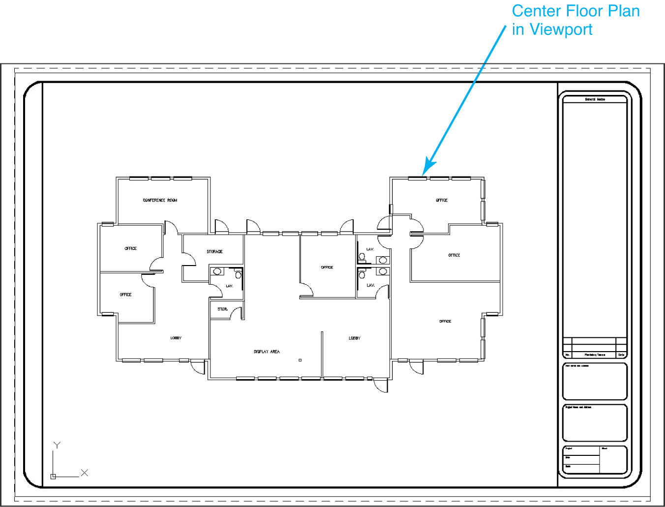
![]() Set the viewport scale to 1/4″ = 1′-0″ using the techniques learned in Exercise 14-3, and center the floor plan in the viewport so it looks similar to Figure 14-43.
Set the viewport scale to 1/4″ = 1′-0″ using the techniques learned in Exercise 14-3, and center the floor plan in the viewport so it looks similar to Figure 14-43.
![]() Rename the Architectural Title Block layout to ANSI D Title Block by right-clicking with your mouse on the Architectural Title Block tab and selecting Rename from the shortcut menu.
Rename the Architectural Title Block layout to ANSI D Title Block by right-clicking with your mouse on the Architectural Title Block tab and selecting Rename from the shortcut menu.
![]() Rename the Layout2 layout to ANSI B Title Block by right-clicking with your mouse on the Layout2 tab and selecting Rename from the shortcut menu.
Rename the Layout2 layout to ANSI B Title Block by right-clicking with your mouse on the Layout2 tab and selecting Rename from the shortcut menu.
![]() Delete the Layout1 layout by right-clicking with your mouse on the Layout1 tab and selecting Delete from the shortcut menu.
Delete the Layout1 layout by right-clicking with your mouse on the Layout1 tab and selecting Delete from the shortcut menu.
![]() Save the drawing.
Save the drawing.
Paper Space Linetype Scale
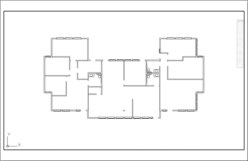
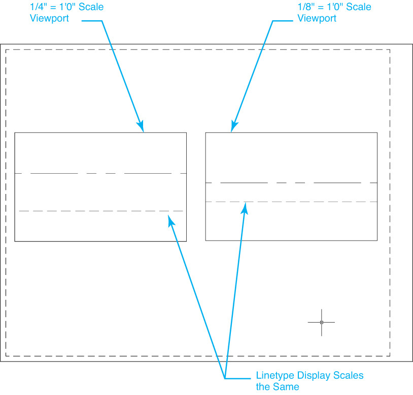
The PSLTSCALE system variable allows you to scale linetype definitions based on the viewport scale so that linetype definitions will display the same in multiple viewports that have different scale factors. Without paper space linetype scaling, the same linetype definition will appear at different scales in each viewport as shown in Figure 14-44.
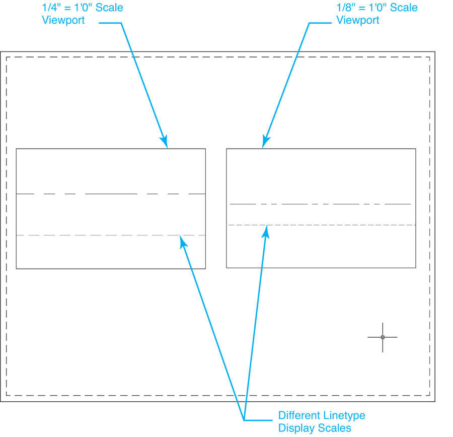
Setting PSLTSCALE to 1 (on) tells AutoCAD to scale the linetype definitions of all the objects displayed in a viewport by the inverse of the viewport scale factor as shown in Figure 14-45.
Be aware that the global linetype scale controlled using the LTSCALE system variable is still in effect when paper space linetype scale is turned on and can have some unintended effects. Typically, the LTSCALE system variable is set to 1 when paper space linetype scale is being used (PSLTSCALE = 1).
For More Details
See page 234 in Chapter 6 for more information about linetype definitions and the LTSCALE system variable.
Exercise 14-6 Paper Space Linetype Scaling
![]() Continue from Exercise 14-5.
Continue from Exercise 14-5.
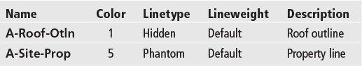
![]() Create the following layers:
Create the following layers:
![]() Set the PSLTSCALE system variable to 1 so paper space linetype scaling is turned on.
Set the PSLTSCALE system variable to 1 so paper space linetype scaling is turned on.
![]() Set the LTSCALE system variable to 1 to so that global linetype scaling is turned off.
Set the LTSCALE system variable to 1 to so that global linetype scaling is turned off.
![]() Switch to the ANSI D Title Block layout.
Switch to the ANSI D Title Block layout.
![]() Maximize the viewport using the Maximize Viewport button on the status bar so you can work in model space through the viewport.
Maximize the viewport using the Maximize Viewport button on the status bar so you can work in model space through the viewport.
![]() Set the A-Roof-Otln layer current in the Layer list box.
Set the A-Roof-Otln layer current in the Layer list box.
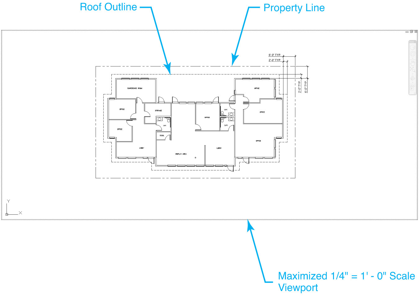
![]() Create the roof outline as shown in Figure 14-46. Do not draw dimensions.
Create the roof outline as shown in Figure 14-46. Do not draw dimensions.
![]() Set the A-Site-Prop layer current in the Layer list box.
Set the A-Site-Prop layer current in the Layer list box.
![]() Create the property line as shown in Figure 14-46. Do not draw dimensions.
Create the property line as shown in Figure 14-46. Do not draw dimensions.
![]() Switch to the ANSI B Title Block layout.
Switch to the ANSI B Title Block layout.
![]() The roof outline and property line should also appear scaled correctly in the 1/8″ = 1′-0″ viewport.
The roof outline and property line should also appear scaled correctly in the 1/8″ = 1′-0″ viewport.
![]() Save the drawing.
Save the drawing.
Chapter Summary
In this chapter, we explained the different ways to set up and lay out a drawing using paper space techniques so that it is ready for output to the associated printer, plotter, or other output device.
As you found out in this chapter, using paper space to lay out a drawing is the industry standard for good reason. Using the techniques and methods you learned in this chapter will enable you to take advantage of benefits that include:
• Creating multiple layouts that are different sheet sizes
• Associating multiple printer/plotter devices to create different output results
• Setting up layouts with multiple scale views
• Controlling layer visibility individually per layout viewport
• Modifying viewports using grips and standard AutoCAD commands
In addition, we learned how to solve the problem of displaying noncontinuous linetypes (i.e., Hidden, Dashed, Center) at different scale factors on the same drawing using the paper space linetype scaling feature. When the PSLTSCALE system variable is set to 1 and paper space linetype scaling is on, noncontinuous lines appear exactly the same in different scale viewports.
Chapter Test Questions
Multiple Choice
Circle the correct answer.
1. Most of a drawing’s line work and annotation features are drawn in:
a. Paper space
b. Model space
c. Drawing space
d. None of the above
2. The paper size of a layout is controlled via its:
a. Drawing limits
b. Associated plotting device
c. b and d
d. Page setup
3. The user-defined window created in a paper space layout that allows you to view and scale information in model space is referred to as a:
a. Layout portal
b. Layout viewport
d. Layout aperture
4. The printable area of a layout is represented by:
a. Shadow
b. Edge of the layout
c. Dashed line
d. Drawing limits
5. The command used to create a layout viewport is:
a. MVIEW
b. VPORTS
c. -VPORTS
d. All of the above
6. The layout viewport creation option that creates a viewport the same size as a layout’s printable area is:
a. Polygonal
b. Object
c. Fit
d. Restore
7. To make a layout viewport current:
a. Double-click with the mouse inside the viewport
b. Type MS<Enter>
c. Type PS<Enter>
d. a and b
8. The scale of a layout viewport can be set using:
a. The Viewport Scale list on the status bar
b. The ZOOM command to specify a zoom scale factor
c. The Properties palette
d. All of the above
9. To prevent a viewport scale from changing accidentally, it is best to:
a. Turn the viewport off
b. Work only in model space
c. Freeze the viewport layer
d. Lock the viewport display
10. The system variable used to control whether paper space linetype scaling is on or off is:
a. PSLTSCALE
b. LTSCALE
c. PAPERSCALE
d. All of the above
True or False
Circle the correct answer.
1. True or False: Most drawing line work and annotation features are drawn in model space.
2. True or False: You cannot locate any drawing information in a paper space layout.
3. True or False: The associated printer/plotter device determines what paper sizes are available.
4. True or False: Layout viewport scale is controlled by zooming in and out in a viewport.
5. True or False: Setting the associated plot device to None allows you select any standard paper size.
6. True or False: A layout viewport is treated like most other AutoCAD drawing objects (lines, circles, etc.).
7. True or False: It is not possible to create circular viewports.
8. True or False: It is possible to add your own custom scales to the AutoCAD standard Scale List.
9. True or False: It is possible to freeze and thaw layer information in each individual viewport.
10. True or False: The shape of a viewport cannot be changed; it must be deleted and then re-created in the new shape.
Chapter Projects
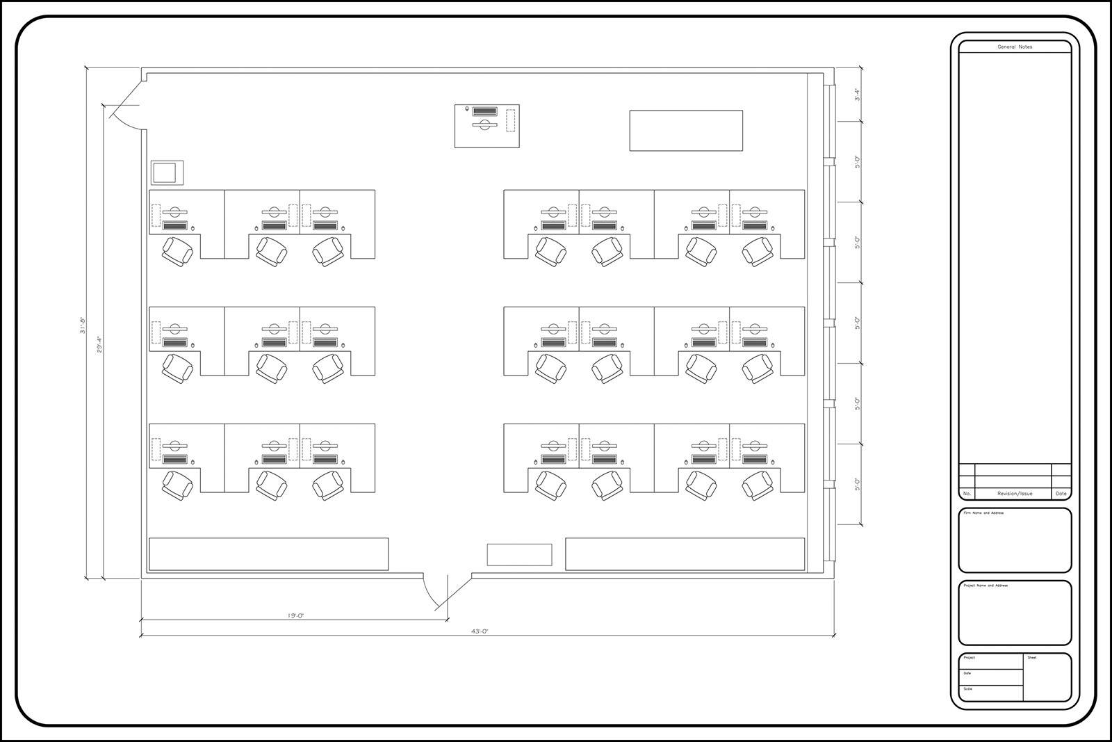
![]() Project 14-1: Classroom Plan, continued from Chapter 13 [BASIC]
Project 14-1: Classroom Plan, continued from Chapter 13 [BASIC]
1. Open drawing P13-1 from Chapter 13.
2. Right-click on a layout tab and select From template... from the shortcut menu to import a layout.
3. Open the Architectural D-Size.dwt drawing template in the student data files, and import the Architectural Title Block layout from the template.
To access student data files, go to www.pearsondesigncentral.com.
4. Select the Architectural Title Block layout to set it current. There is a single viewport in this layout. Make the viewport current by double-clicking inside the viewport boundary.
5. Zoom Extents so the drawing fills the viewport, and set the Viewport Scale to 1/2″ = 1′-0″. Position the drawing within the viewport so it matches Figure 14-47.
6. Switch back to paper space by double-clicking outside the viewport.
7. Delete the Layout1 and Layout2 layouts.
8. Save the drawing as P14-1.
![]() Project 14-2: B-Size Mechanical Border, continued from Chapter 13 [INTERMEDIATE]
Project 14-2: B-Size Mechanical Border, continued from Chapter 13 [INTERMEDIATE]
1. Open template file Mechanical B-Size.DWT from Chapter 13.
2. Press the <Ctrl>+A keyboard combination to select everything in the drawing.
3. Press the <Ctrl>+<Shift>+C keyboard combination, and specify 0,0 as the base point.
4. Press the <Del> key or use the ERASE command to delete all the selected objects.
5. Select the Layout1 tab to switch to paper space.
6. Erase the existing default viewport.
7. Use the Page Setup Manager to set the associated plotter to None and the paper size to ANSI B (17.00 × 11.00 Inches).
8. Press the <Ctrl>+V keyboard combination and enter –.25,–.75 when AutoCAD prompts you to Specify insertion point: to paste the title border in paper space.
9. Create a polygonal viewport on layer Viewport at the inside border edges as shown in Figure 14-48.
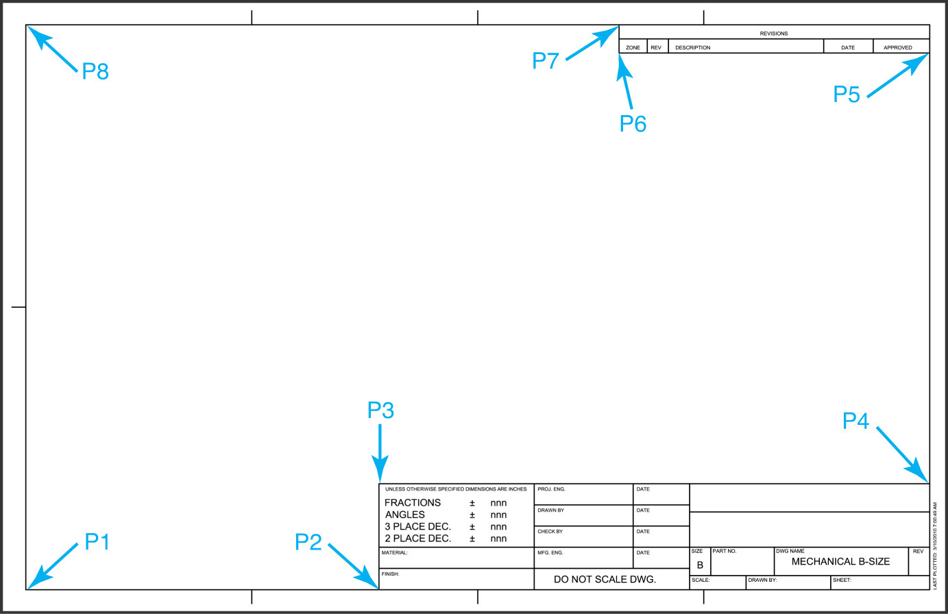
10. Rename the Layout1 layout to Mechanical B-Size and delete the Layout2 layout.
11. Save the drawing as a template file named Mechanical B-Size.DWT.
![]() Project 14-3: Architectural D-Size Border, continued from Chapter 13 [ADVANCED]
Project 14-3: Architectural D-Size Border, continued from Chapter 13 [ADVANCED]
1. Open template file Architectural D-Size.DWT from Chapter 13.
2. Press the <Ctrl>+A keyboard combination to select everything in the drawing.
3. Press the <Ctrl>+<Shift>+C keyboard combination, and select the bottom left corner of the border corner tick marks using the Endpoint object snap.
4. Press the <Del> key or use the ERASE command to delete all the selected objects.
5. Select the Layout1 tab to switch to paper space.
6. Erase the existing default viewport.
7. Use the Page Setup Manager to set the associated plotter to None and the paper size to ARCH D (36.00 × 24.00 Inches).
8. Press the <Ctrl>+V keyboard combination and enter –.25, –.75 when AutoCAD prompts you to Specify insertion point: to paste the title border in paper space.
9. Create a rectangular viewport on layer A-Anno-Vprt at the inside border edges as shown in Figure 14-49.
10. Rename the Layout1 layout to Architectural D-Size, and delete the Layout2 layout.
11. Make sure that paper space is the current drawing environment by double-clicking outside the viewport.
12. Save the drawing to a template file as Architectural D-Size.DWT.
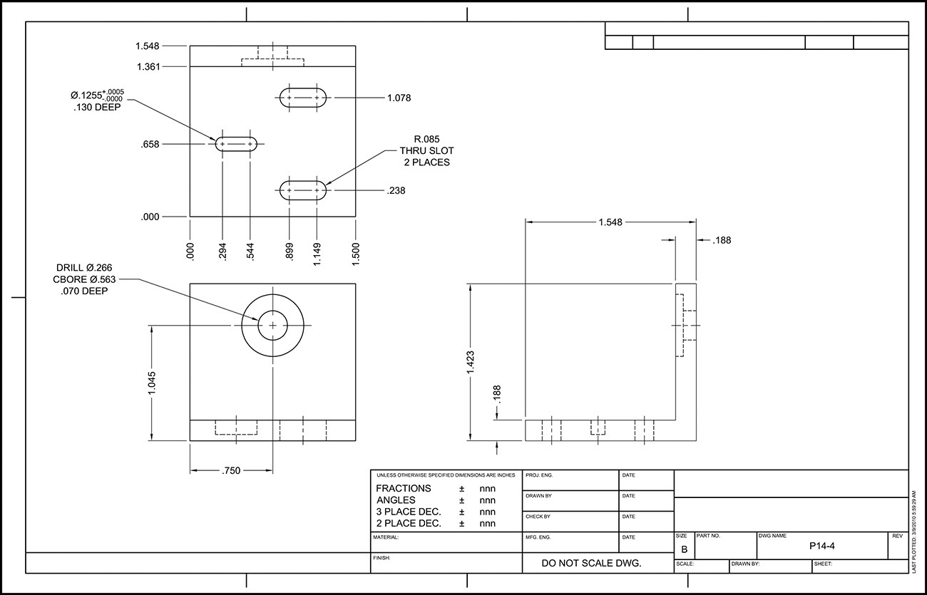
![]() Project 14-4: Optical Mount—English Units, continued from Chapter 13 [INTERMEDIATE]
Project 14-4: Optical Mount—English Units, continued from Chapter 13 [INTERMEDIATE]
1. Open drawing P13-4 from Chapter 13.
2. Select From template... from the Layout right-click menu to import a layout.
3. Import the Mechanical B-Size layout and border from the Mechanical B-Size.dwt template file created in Project 14-2.
4. Select the Mechanical B-Size layout to make it current.
5. Set the viewport scale to 2:1 and center the view as shown in Figure 14-50.
6. Lock the viewport display so the view scale doesn’t change.
7. Delete the Layout1 and Layout2 layouts.
8. Save the drawing as P14-4.
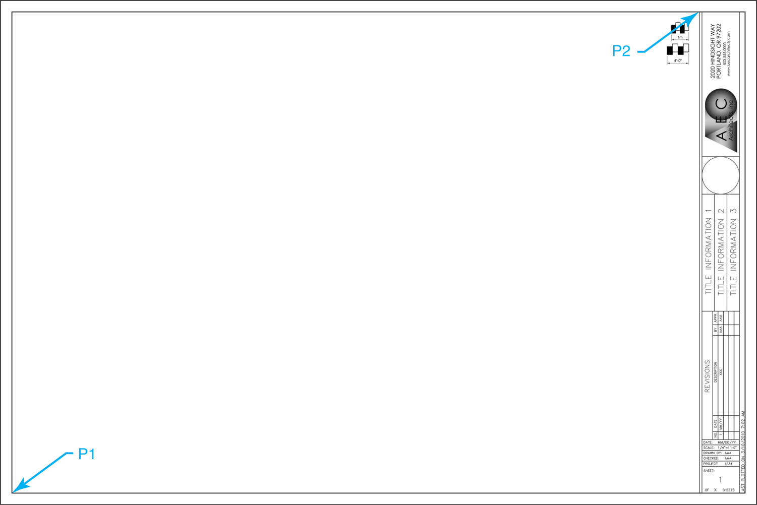
![]() Project 14-5: Residential Architectural Plan, continued from Chapter 13 [ADVANCED]
Project 14-5: Residential Architectural Plan, continued from Chapter 13 [ADVANCED]
1. Open drawing P13-5 from Chapter 13.
2. Select From template... from the Layout right-click menu to import a layout.
3. Import the Architectural D-Size layout and border from the Architectural D-Size.dwt template file created in Project 14-3.
4. Select the Architectural D-Size layout to make it current.
5. Set the viewport scale to 1/4″ = 1′-0″ and center the view as shown in Figure 14-51.
6. Lock the viewport display so the view scale doesn’t change.
7. Delete the Layout1 and Layout2 layouts.
8. Save the drawing as P14-5.