Chapter 8
Troubleshooting Open Shortest Path First (OSPF)
This chapter covers the following topics:
Open Shortest Path First (OSPF) is a link-state routing protocol that provides every router with a complete map for all destination networks. Every router in the network calculates the best, shortest, loop-free paths using this complete map of the network.
This chapter focuses on identifying and troubleshooting issues that are caused with forming OSPF neighbor adjacency, path selection, and missing routes.
OSPF Fundamentals
OSPF advertises link-state advertisements (LSA) that contain the link state and metric to neighboring routers. Received LSAs are stored in a local database called the link-state database (LSDB), which are then advertised to neighboring routers exactly as the LSAs were received. The same LSA is flooded throughout the OSPF area just as the advertising router advertised it. The LSDB provides the topology of the network, in essence providing the router a complete map of the network.
All routers run the Dijkstra Shortest Path First (SPF) algorithm to construct a loop-free topology of shortest paths. Each router sees itself as the top of the tree, and the tree contains all network destinations within the OSPF domain. The SPF Tree (SPT) is different for each OSPF router, but the LSDB used to calculate the SPT is identical for all OSPF routers in that area.
Inter-Router Communication
OSPF runs on its own protocol (89) and multicast where possible to reduce unnecessary traffic. The two OSPF multicast addresses are as follows:
AllSPFRouters: IPv4 Address 224.0.0.5 or MAC 01:00:5E:00:00:05
All routers running OSPF should be able to receive these packets.
AllDRouters: IPv4 Address 224.0.0.6 or MAC 01:00:5E:00:00:06
Communication with Designated Routers uses this address.
Within the OSPF protocol are five types of packets. Table 8-1 provides an overview of the OSPF packet types and a brief description for each type.
Type |
Packet Name |
Functional Overview |
1 |
Hello |
Discover & Maintain neighbors Packets are sent out periodically on all OSPF interfaces to discover new neighbors while ensuring other neighbors are still online. |
2 |
Database Description (DBD) or (DDP) |
Summarize Database Contents Packets are exchanged when an OSPF adjacency is first being formed. These packets are used to describe the contents of the LSDB. |
3 |
Link State Request (LSR) |
Database Download When a router thinks that part of its LSDB is stale, it may request a portion of a neighbor’s database using this packet type. |
4 |
Link State Update (LSU) |
Database Update This is an explicit LSA for a specific network link and normally is sent in direct response to a LSR. |
5 |
Link State Ack |
Flooding Acknowledgement These packets are sent in response to the flooding of LSAs, therefore making the flooding a reliable transport feature. |
OSPF Hello Packets
OSPF Hello packets are responsible for discovering and maintaining neighbors. In most instances, the router sends Hello packets to the AllSPFRouters address (224.0.0.5). Table 8-2 provides a listing of some of the data contained within an OSPF Hello packet.
Data Field |
Description |
Router-ID (RID) |
A unique 32-bit ID within an OSPF domain. |
Authentication Options |
Allows secure communication between OSPF routers to prevent malicious activity. Options are None, Clear Text, or MD5. |
Area-ID |
OSPF area that the OSPF interface belongs to. It is a 32-bit number that can be written in dotted decimal format (0.0.1.0) or decimal (256). |
Interface Address Mask |
The network mask for the primary IP for the interface that the Hello is sent out. |
Interface Priority |
Router Interface priority for Designated Router elections. |
Hello Interval |
Time span, in seconds, that a router sends out Hello packets on the interface. |
Dead Interval |
Time span, in seconds, that a router will wait to hear a Hello from a neighbor router before it declares that router Down. |
Designated Router & Backup Designated Router |
IP address of the Designated Router & Backup Designated Router for that network link. |
Active Neighbor |
A list of OSPF neighbors seen on that network segment. Must have received a Hello from the neighbor within the Dead Interval. |
Neighbor States
An OSPF neighbor is a router that shares a common OSPF-enabled network link. OSPF routers discover other neighbors via the OSPF Hello packets. An adjacent OSPF neighbor is an OSPF neighbor that shares a synchronized OSPF database between the two neighbors.
Each OSPF process maintains a table for adjacent OSPF neighbors and the state of each router. Table 8-3 provides an overview of the OSPF neighbor states.
Table 8-3 OSPF Neighbor States
State |
Description |
Down |
Initial state of a neighbor relationship. It indicates that it has not received any LSAs from that router. |
Attempt |
This state is relevant to nonbroadcast multiple access (NBMA) networks that do not support broadcast and require explicit neighbor configuration. This state indicates that no recent information has been received, but the router is still attempting communication. |
Init |
A Hello packet has been received from another a router, but bidirectional communication has not been established. |
2-Way |
Bidirectional communication has been established. If a Designated Router or Backup Designated Router is needed, the election occurs during this state. |
ExStart |
This is the first state of forming an adjacency. Routers identify which router will be the master or slave for the LSDB synchronization. |
Exchange |
During this state, routers are exchanging link-states and via DBD packets. |
Loading |
LSR packets are sent to the neighbor asking for the more recent LSAs that have been discovered (but not received) in the Exchange state. |
Full |
Neighboring routers are fully adjacent. |
Designated Routers
Multi-access networks such as Ethernet (LANs) allow more than two routers to exist on a network segment. This could cause scalability problems with OSPF as the number of routers on a segment increases. Additional routers flood more LSAs on the segment, and OSPF traffic becomes excessive as OSPF neighbor adjacencies increase. If 6 routers share the same multi-access network, 15 OSPF adjacencies would form along with 15 occurrences of database flooding on that one network.
Multi-access networks overcome this inefficiency by using a Designated Router (DR). DRs reduce the number of OSPF adjacencies on a multi-access network segment because routers only form a full OSPF adjacency with the DR and not each other. The DR is then responsible for flooding the update to all OSPF routers on that segment as updates occur.
If the DR fails, OSPF must form new adjacencies invoking all new LSAs and could potentially cause a temporary loss of routes. In the event of DR failure, a Backup Designated Router (BDR) becomes the new DR; then an election occurs to replace the BDR. To minimize transition time, the BDR also forms a full OSPF adjacency with all OSPF routers on that segment.
The DROther is a router on the DR-enabled segment that is not the DR or the BDR; it is simply the other router.
Note
Neighbors are selected as the DR and BDR based on the highest OSPF priority, followed by higher Router ID (RID) when the priority is a tie. The OSPF priority is set on an interface with the command ip ospf priority 0-255. Setting the value to zero prevents that router from becoming a DR for that segment.
Areas
OSPF provides scalability for the routing table by using multiple OSPF areas with the routing domain. Each OSPF area provides a collection of connected networks and hosts that are grouped together. OSPF uses a two-tier hierarchical architecture where Area 0 is a special area known as the backbone, and all other OSPF areas must connect to Area 0. In other words, Area 0 provides transit connectivity between nonbackbone areas. Nonbackbone areas advertise routes into the backbone, and the backbone then advertises routes into other nonbackbone areas.
The exact topology of the area is invisible from outside of the area while still providing connectivity to routers outside of the area. This means that routers outside the area do not have a complete topological map for that area, which reduces OSPF network traffic in that area. By segmenting an OSPF routing domain into multiple areas, it is no longer true that all OSPF routers will have identical LSDBs; however, all routers within the same area will have identical area LSDBs. The reduction in routing traffic uses less router memory and resources providing scalability.
Area Border Routers (ABR) are OSPF routers connected to Area 0 and another OSPF area. ABRs are responsible for advertising routes from one area and injecting them into a different OSPF area. Every ABR needs to participate in Area 0; otherwise, routes do not advertise into another area.
When a router redistributes external routes into an OSPF domain, the router is called an Autonomous System Boundary Router (ASBR). An ASBR can be any OSPF router, and the ASBR function is independent of the ABR function.
Link State Advertisements
Understanding how OSPF builds a topology table and the how various link state advertisement (LSA) types function helps with troubleshooting missing routes. Table 8-4 provides a summary of the OSPF LSAs discussed.
LSA Type |
Description |
1 |
Router Link—Every OSPF router advertises a Type-1 LSA. Type-1 LSAs are the most basic LSA within the LSDB. A Type-1 LSA entry exists for all OSPF enabled links (that is, interfaces) and reflects an actual network. Router links are classified either as either stub or transit. A stub router link includes a netmask, whereas a transit link does not. |
2 |
Network Link—Type-2 LSAs represent multi-access network segments that use a DR. The DR always advertises the Type-2 LSA, and connects the Type-1 transit link type LSAs together. Type-2 LSAs also provide the network mask for the Type-1 transit link types. |
|
If a DR has not been elected, a Type-2 LSA is not present in the LSDB because the corresponding Type-1 transit link type LSA will be a stub. Type-2 LSAs are not flooded outside of the originating OSPF area in an identical fashion to Type-1 LSAs. |
3 |
Summary Link—The role of the ABRs is to participate in multiple OSPF areas and ensure that the networks associated with Type-1 LSAs are reachable in the non-originating OSPF area. ABRs do not forward Type-1 or Type-2 LSAs into other areas. When an ABR receives a Type-1 LSA, it creates a Type-3 LSA referencing the network in the original Type-1 LSA. A Type-2 LSA is used to determine the network mask of a multi-access network. The ABR then advertises the Type-3 LSA into other areas. If an ABR receives a Type-3 LSA from Area 0 (backbone), it generates a new Type-3 LSA for the nonbackbone area, but lists itself as the advertising router. |
4 |
ASBR Summary—Type-4 LSAs locate the ASBR for Type-5 LSAs. A Type-5 LSA is flooded through the OSPF domain unmodified, and the only mechanism to identify the ASBR is the RID. Routers examine the Type-5 LSA, check to see if the RID is in the local area, and if it is not, they require a mechanism to locate the ASBR. Only Type-1 or Type-2 LSAs provide a method to locate the RID within an area. The Type-4 LSA provides a way for routers to locate the ASBR when the router is in a different area from the ASBR. |
5 |
AS External—When a route is redistributed into OSPF on the ASBR, the external route is flooded throughout the entire OSPF domain as a Type-5 LSA. Type-5 LSAs are not associated to a specific area and are flooded across all ABRs. Only the LSA age is modified during flooding. |
7 |
NSSA External—Not So Stubby Areas (NSSA) areas are a method to reduce the LSDB within an area by preventing Type-4 and Type-5 LSAs while allowing redistribution of networks into the area. A Type-7 LSA exists only in NSSA areas where the route redistribution is occurring. An ASBR injects external routes as Type-7 LSAs into an NSSA area. The ABR does not advertise Type-7 LSAs outside of the originating NSSA area, but advertises a Type-5 LSA for the other OSPF areas. If the Type-5 LSA crosses Area 0, then the second ABR creates a Type-4 LSA for the Type-5 LSA. |
Note
Every LSA contains the advertising router’s RID. The router RID represents the router and is how links are connected to each other.
Figure 8-1 displays a multi-area OSPF topology with an external route redistributed into Area 56. On the left of the figure is the network prefix for the topology, and the appropriate LSA type is displayed underneath the segment it is advertised. This demonstrates where each LSA is located. Notice that Area 1234 is a broadcast area and contains a DR, which generates a Type-2 LSA. NX-6 is redistributing the 100.65.0.0/16 network into OSPF, whereas NX-5 advertises the first Type-4 LSA for the ASBR (NX-6).
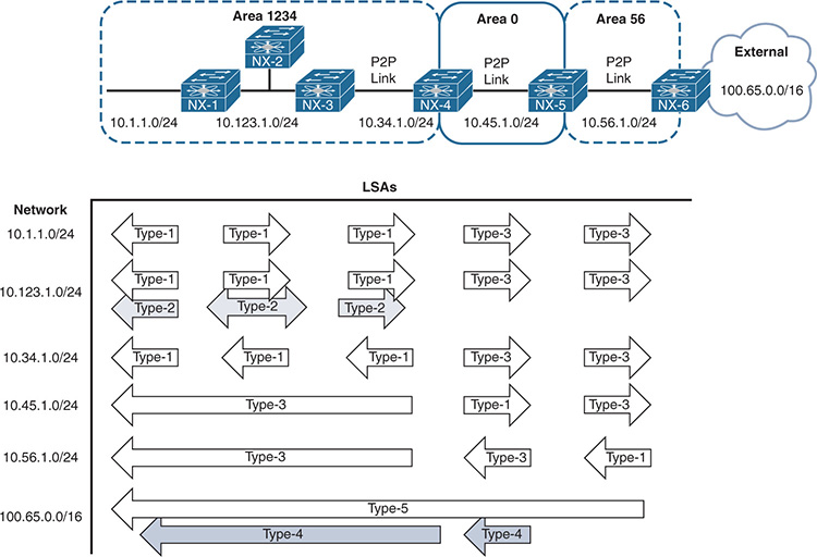
Figure 8-1 Topology to Demonstrate OSPF LSAs
Note
The Cisco Press book IP Routing on Cisco IOS, IOS XE and IOS XR describes OSPF LSAs and how a router builds the actual topology table using LSAs in a visual manner.
OSPF classifies routes into the following three categories:
Intra-area routes: Routes for networks that exist in that OSPF area and contain intra beside them in the routing table.
Inter-area routes: Routes for networks that exist in the OSPF domain from a different OSPF area and contain inter beside them in the routing table.
External routes: Routes that were redistributed into the OSPF domain and contain a type-1 or type-2 beside them in the routing table.
Example 8-1 displays the routing table from NX-1 from Figure 8-1 that includes intra-area, inter-area, and external OSPF routes.
Example 8-1 Sample OSPF Routing Table
IP Route Table for VRF "default"
'*' denotes best ucast next-hop
'**' denotes best mcast next-hop
'[x/y]' denotes [preference/metric]
'%<string>' in via output denotes VRF <string>
10.34.1.0/24, ubest/mbest: 1/0
*via 10.123.1.3, Eth1/1, [110/80], 00:10:30, ospf-NXOS, intra
10.45.1.0/24, ubest/mbest: 1/0
*via 10.123.1.3, Eth1/1, [110/120], 00:10:15, ospf-NXOS, inter
10.56.1.0/24, ubest/mbest: 1/0
*via 10.123.1.3, Eth1/1, [110/160], 00:10:15, ospf-NXOS, inter
10.65.0.0/16, ubest/mbest: 1/0
*via 10.123.1.3, Eth1/1, [110/20], 00:08:02, ospf-NXOS, type-2
Troubleshooting OSPF Neighbor Adjacency
Now that an overview of the OSPF protocol has been provided, let’s review how OSPF is configured and how to troubleshoot OSPF neighbor adjacencies for NX-OS.
Baseline OSPF Configuration
The OSPF configuration process on a NX-OS switch requires configuration under the OSPF process and under the interface configuration submode. The following steps explain the process for configuring OSPF on a NX-OS device:
Step 1. Enable the OSPF feature. The OSPF feature must be enabled with the global configuration command feature ospf.
Step 2. Define an OSPF process tag. The OSPF process must be defined with the global configuration command router ospf process-tag. The process-tag can be up to 20 alphanumeric characters in length.
Step 3. Enable OSPF neighbor logging (recommended). NX-OS does not log OSPF neighbor adjacencies forming or dissolving by default. The OSPF configuration command log-adjacency-changes [detail] enables logging and is recommended. The optional detail keyword lists out the OSPF neighbor states from Table 8-3 as they are entered.
Step 4. Define the Router-ID (recommended). The OSPF Router-ID (RID) is a 32-bit unique number that identifies an OSPF router and is synonymous with the term Neighbor ID. The RID must be unique for each OSPF process in an OSPF domain as it is used to build the topology table. The command router-id router-id is used to statically set the RID.
If the RID is not manually configured, the Loopback 0 IP address is always preferred. If the Loopback 0 does not exist, NX-OS selects the IP address for the first loopback interface in the configuration. If no loopback interfaces exist, NX-OS selects the IP address for the first physical interface in the configuration.
Step 5. Enable OSPF on interfaces. The interface that OSPF is enabled on is selected with the command interface interface-id. The OSPF process is then enabled on that interface with the command ip router ospf process-tag area area-id. The area-id can be entered in decimal format (1-65,536) or dotted-decimal format, but it is always stored in dotted decimal format.
Secondary networks are advertised by default after OSPF is enabled on that interface. This behavior is disabled with the command ip router ospf process-tag area area-id secondaries none.
Loopback interfaces are advertised as a /32 regardless of the actual subnet mask. The command ip ospf advertise-subnet changes the behavior so that the subnet mask is advertised with the LSA.
Note
Typically, an interface can exist in only one area at a time. However, recent changes allow an interface to exist in multiple areas across only point-to-point OSPF links with the command ip router ospf process-tag multi-area area-id.
The configuration in Example 8-2 enables OSPF only on interfaces Ethernet1/1, VLAN 10, and Loopback 0.
Example 8-2 Baseline OSPF Configuration
Enter configuration commands, one per line. End with CNTL/Z.
NX-1(config)# feature ospf
NX-1(config)# router ospf NXOS
NX-1(config-router)# log-adjacency-changes detail
NX-1(config-router)# router-id 192.168.100.100
NX-1(config-if)# ip router ospf NXOS area 0
NX-1(config-if)# interface vlan 10
NX-1(config-if)# ip router ospf NXOS area 0
NX-1(config-if)# interface e1/1
NX-1(config-if)# ip router ospf NXOS area 0
12:58:33 NX-1 %$ VDC-1 %$ %OSPF-5-NBRSTATE: ospf-NXOS [13016] Process NXOS, Nbr 10.12.1.200 on Ethernet1/1 from DOWN to INIT, HELLORCVD
12:58:42 NX-1 %$ VDC-1 %$ %OSPF-5-NBRSTATE: ospf-NXOS [13016] Process NXOS, Nbr 10.12.1.200 on Ethernet1/1 from INIT to EXSTART, ADJOK
12:58:42 NX-1 %$ VDC-1 %$ %OSPF-5-NBRSTATE: ospf-NXOS [13016] Process NXOS, Nbr 10.12.1.200 on Ethernet1/1 from EXSTART to EXCHANGE, NEGDONE
12:58:42 NX-1 %$ VDC-1 %$ %OSPF-5-NBRSTATE: ospf-NXOS [13016] Process NXOS, Nbr 10.12.1.200 on Ethernet1/1 from EXCHANGE to LOADING, EXCHDONE
12:58:42 NX-1 %$ VDC-1 %$ %OSPF-5-NBRSTATE: ospf-NXOS [13016] Process NXOS, Nbr 10.12.1.200 on Ethernet1/1 from LOADING to FULL, LDDONE
OSPF requires a neighbor relationship to form before routes are processed and added to the RIB. The neighbor adjacency table is vital for tracking neighbor status and the updates sent to each neighbor. This section explains the process for troubleshooting OSPF neighbor adjacencies on NX-OS switches.
Figure 8-2 provides a simple topology with two Nexus switches that are used to explain how to troubleshoot OSPF adjacency problems.
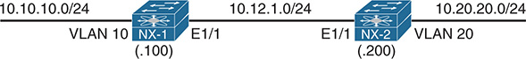
Figure 8-2 Simple Topology with Two NX-OS Switches
OSPF Neighbor Verification
First, verify devices that have successfully established an OSPF adjacency with the command show ip ospf neighbors [interface-id [detail | summary] | neighbor-id [detail] | vrf {vrf-name | all}] [summary]. The summary keyword displays the count of OSPF neighbors and the interface that those neighbors are associated with.
Example 8-3 demonstrates a couple iterations of the command being run on NX-1. Notice the additional information like Dead timer and last change that is included with the detail keyword.
Example 8-3 Display of OSPF Neighbors
OSPF Process ID NXOS VRF default
Total number of neighbors: 2
Neighbor ID Pri State Up Time Address Interface
192.168.200.200 1 FULL/DR 00:02:04 10.12.1.200 Eth1/1
OSPF Process ID NXOS VRF default, Neighbor Summary
Interface Down Attempt Init TwoWay ExStart Exchange Loading Full Total
Total 0 0 0 0 0 0 0 1 1
Eth1/1 0 0 0 0 0 0 0 1 1
Neighbor 192.168.200.200, interface address 10.12.1.200
Process ID NXOS VRF default, in area 0.0.0.0 via interface Ethernet1/1
State is FULL, 6 state changes, last change 00:03:21
Neighbor priority is 1
DR is 10.12.1.200 BDR is 10.12.1.100
Hello options 0x2, dbd options 0x42
Last non-hello packet received never
Dead timer due in 00:00:34
Table 8-5 provides a brief overview of the fields that appear in Example 8-3.
Table 8-5 OSPF Neighbor State Fields
Field |
Description |
Neighbor ID |
Router-ID (RID) of neighboring router. |
PRI |
Priority for the neighbor’s interface. This is used for DR/BDR elections. |
State |
The first field is the neighbor state as described in Table 8-3. The second field is the DR, BDR, or DROther role if the interface requires a DR. For non-DR network links, the second field will show ‘-'. Looking at an OSPF neighbor’s state is helpful when troubleshooting adjacency issues. Depending on the LSDB size, the state may transition faster than you can see. |
Dead Time |
Dead time left until the router is declared unreachable. |
Address |
Primary IP address for the OSPF neighbor. |
Interface |
Local interface that the OSPF neighbor is attached to. |
Besides enabling OSPF on the network interfaces of an NX-OS device, the following parameters must match for the two routers to become neighbors:
Interfaces must be Active.
Connectivity between devices must exist using the primary subnet.
Maximum transmission unit (MTU) matches between devices.
Router-IDs are unique.
Interface area must match.
OSPF stub area flags match.
Need for DR matches based on OSPF network types.
OSPF Hello and Dead Timers match.
Authentication parameters.
Confirmation of OSPF Interfaces
If a neighbor adjacency is missing, it is important to verify that the correct interfaces are running OSPF. The command show ip ospf interface [brief] shows the OSPF-enabled interfaces. Example 8-4 provides output for the brief version of the commands.
Example 8-4 OSPF Interface Output in Brief Format
OSPF Process ID NXOS VRF default
Total number of interface: 3
Interface ID Area Cost State Neighbors Status
Eth1/1 2 0.0.0.0 4 BDR 1 up
VLAN10 3 0.0.0.0 4 DR 0 up
Lo0 1 0.0.0.0 1 LOOPBACK 0 up
Table 8-6 provides an overview of the fields in the output from Example 8-3.
Table 8-6 OSPF Interface Columns
Field |
Description |
Interface |
Interfaces with OSPF enabled. |
Area |
The Area that this interface is associated with. Area is always displayed in dotted-decimal format. |
Cost |
Cost is used to calculate a metric for a path by the SPF algorithm. |
State |
Current interface state DR, BDR, DROTHER, LOOP, or Down. |
Neighbor |
Number of neighbor OSPF routers for a segment that have established an adjacency. |
Status |
The protocol line status for that interface. A down value reflects an interface that is not reachable. |
Example 8-5 displays the output of the show ip ospf interface command in nonbrief format. It is important to note that the primary IP address, interface network type, DR, BDR, and OSPF interface timers are included as part of the information provided.
Example 8-5 OSPF Interface Output
IP address 10.12.1.100/24
Process ID NXOS VRF default, area 0.0.0.0
Enabled by interface configuration
State BDR, Network type BROADCAST, cost 4
Index 2, Transmit delay 1 sec, Router Priority 1
Designated Router ID: 192.168.200.200, address: 10.12.1.200
Backup Designated Router ID: 192.168.100.100, address: 10.12.1.100
1 Neighbors, flooding to 1, adjacent with 1
Timer intervals: Hello 10, Dead 40, Wait 40, Retransmit 5
Hello timer due in 00:00:00
No authentication
Number of opaque link LSAs: 0, checksum sum 0
Passive Interface
Some network topologies require advertising a network segment into OSPF, but need to prevent neighbors from forming adjacencies on that segment. A passive interface is displayed when displaying the OSPF interfaces, so the quickest method is to check the OSPF process with the command show ip ospf [process-tag] to see whether any passive interfaces are configured. Example 8-6 displays the command and where the passive interface count is provided.
Example 8-6 Identification if Passive OSPF Interfaces Are Configured
Routing Process NXOS with ID 192.168.100.100 VRF default
..
Area BACKBONE(0.0.0.0)
Area has existed for 00:22:02
Interfaces in this area: 3 Active interfaces: 3
Passive interfaces: 1 Loopback interfaces: 1
Now that a passive interface has been identified, the configuration must be examined for the following:
The interface parameter command ip ospf passive-interface, which makes only that interface passive.
The global OSPF configuration command passive-interface default, which makes all interfaces under that OSPF process passive. The interface parameter command no ip ospf passive-interface takes precedence over the global command and makes that interface active.
Example 8-7 displays the configuration on NX-1 and NX-2 that prevents the two Nexus switches from forming an OSPF adjacency. The Ethernet1/1 interfaces must be active on both switches for an adjacency to form. Move the command ip ospf passive-interface from Eth1/1 to VLAN10 on NX-1, and the command no ip ospf passive-interface from VLAN20 to Interface Eth1/1 on NX-2 to allow an adjacency to form.
Example 8-7 OSPF Configuration with Passive Interfaces
router ospf NXOS
router-id 192.168.100.100
log-adjacency-changes detail
interface loopback0
ip router ospf NXOS area 0.0.0.0
interface Ethernet1/1
interface VLAN10
ip router ospf NXOS area 0.0.0.0
router-id 192.168.200.200
log-adjacency-changes detail
interface loopback0
ip router ospf NXOS area 0.0.0.0
interface Ethernet1/1
ip router ospf NXOS area 0.0.0.0
interface VLAN20
Verification of OSPF Packets
A vital step in troubleshooting OSPF adjacency issues is to ensure that a device is transmitting or receiving OSPF network traffic. The command show ip ospf traffic [interface-id] [detail] displays a high-level summary of packet types that were sent or received from a device.
Example 8-8 displays the use of this command. Notice that there is a separation of errors and valid packets in the output. Executing the command while specifying an interface provides more granular visibility to the packets received or transmitted for an interface.
Example 8-8 OSPF Traffic Statistics
OSPF Process ID NXOS VRF default, Packet Counters (cleared 00:32:34 ago)
Total: 319 in, 342 out
LSU transmissions: first 23, rxmit 4, for req 5 nbr xmit 0
Flooding packets output throttled (IP/tokens): 0 (0/0)
Ignored LSAs: 0, LSAs dropped during SPF: 0
LSAs dropped during graceful restart: 0
Errors: drops in 0, drops out 0, errors in 0,
errors out 0, hellos in 0, dbds in 0,
lsreq in 0, lsu in 0, lsacks in 0,
unknown in 0, unknown out 0, no ospf 0,
bad version 0, bad crc 0, dup rid 0,
dup src 0, invalid src 0, invalid dst 0,
no nbr 0, passive 1, wrong area 14,
pkt length 0, nbr changed rid/ip addr 0
bad auth 0, no vrf 0
bad reserved 0, no vrf 0
hellos dbds lsreqs lsus acks
In: 253 18 5 25 18
Out: 275 19 5 32 11
Debug functionality is used to acquire granularity on various processes on the router. Specifically, the command debug ip ospf {adjacency | hello | packets] displays the processing of packets that have reached the supervisor on the switch. This allows for users to verify if packets were received or advertised from a router.
Example 8-9 displays the use of the OSPF hello and packet debugs.
Example 8-9 OSPF Hello and Packet Debugs
NX-1# debug ip ospf hello
13:59:28.140175 ospf: NXOS [16748] (default) LAN hello out, ivl 10/40, options 0x02, mask /24, prio 1, dr 0.0.0.0, bdr 0.0.0.0 nbrs 0 on Ethernet1/1 (area 0.0.0.0)
13:59:28.140631 ospf: NXOS [16748] (default) sent: prty:6 HELLO to 224.0.0.5/ Ethernet1/1
13:59:29.165361 ospf: NXOS [16748] (default) rcvd: prty:0 ver:2 t:HELLO len:44 rid:192.168.200.200 area:0.0.0.0 crc:0x732d aut:0 aukid:0 from 10.12.1.200/ Ethernet1/1
13:59:29.165460 ospf: NXOS [16748] (default) LAN hello in, ivl 10/40, options 0x02, mask /24, prio 1, dr 0.0.0.0, bdr 0.0.0.0 on Ethernet1/1 from 10.12.1.200
Note
Debug output can also be redirected to a logfile, as shown earlier in Chapter 2, “NX-OS Troubleshooting Tools.”
Table 8-7 provides a brief description of the fields that are provided in the debug output from Example 8-9.
Table 8-7 Relevant Fields for OSPF Debug
Field |
Description |
ivl |
Provides the OSPF Hello and Dead Timers in the Hello packet. |
options |
Identifies the area associated to that interface as a regular OSPF area, OSPF Stub, or OSPF NSSA area. These values are shown in HEX, and this chapter explains later how to verify them. |
mask |
The subnet mask of primary IP address on that interface. |
priority |
The interface priority for DR/BDR elections. |
dr |
The router-id of the DR. |
bdr |
The router-id of the BDR. |
nbrs |
The number of neighbors detected on that network segment. |
Debug commands are generally the least preferred method for finding root cause because of the amount of data that could be generated while the debug is enabled. NX-OS provides event-history that runs in the background without performance hits that provides another method of troubleshooting. The command show ip ospf event-history [hello | adjacency | event] provides helpful information when troubleshooting OSPF adjacency problems. The hello keyword provides the same information as the debug command in Example 8-9.
Example 8-10 displays the show ip ospf event-history hello command. Examine the difference in the sample output on NX-1.
Example 8-10 Hello Packet Visibility from OSPF Event History
OSPF HELLO events for Process "ospf-NXOS"
18:20:03.890150 ospf NXOS [16748]: LAN hello out, ivl 10/40, options 0x02, mask /24, prio 1, dr 10.12.1.200, bdr 0.0.0.0 nbrs 1 on Ethernet1/1 (area 0.0.0.0)
18:19:59.777890 ospf NXOS [16748]: LAN hello in, ivl 10/40, options 0x02, mask /24, prio 1, dr 10.12.1.200, bdr 0.0.0.0 on Ethernet1/1 from 10.12.1.200
18:19:56.320192 ospf NXOS [16748]: LAN hello out, ivl 10/40, options 0x02, mask /24, prio 1, dr 10.12.1.200, bdr 0.0.0.0 nbrs 1 on Ethernet1/1 (area 0.0.0.0)
18:19:52.101250 ospf NXOS [16748]: LAN hello in, ivl 10/40, options 0x02, mask /24, prio 1, dr 10.12.1.200, bdr 0.0.0.0 on Ethernet1/1 from 10.12.1.200
Performing OSPF debugs on a switch only shows the packets that have reached the supervisor. If packets are not displayed in the debugs or event-history, further troubleshooting must be taken by examining quality of service (QoS) policies, control plane policing (CoPP), or just verification of the packet leaving or entering an interface.
QoS policies may or may not be deployed on an interface. If they are deployed, the policy-map must be examined for any drop packets, which must then be referenced to a class-map that matches the OSPF routing protocol. The same process applies to CoPP policies because they are based on QoS settings as well.
Example 8-11 displays the process for checking a switch’s CoPP policy with the following logic:
Examine the CoPP policy with the command show running-config copp all. This displays the relevant policy-map name, classes defined, and the police rate.
Investigate the class-maps to identify the conditional matches for that class-map.
After the class-map has been verified, examine the policy-map drops for that class with the command show policy-map interface control-plane.
Example 8-11 Verification of CoPP for OSPF
class-map type control-plane match-any copp-system-p-class-critical
match access-group name copp-system-p-acl-bgp
match access-group name copp-system-p-acl-rip
match access-group name copp-system-p-acl-vpc
match access-group name copp-system-p-acl-bgp6
match access-group name copp-system-p-acl-lisp
policy-map type control-plane copp-system-p-policy-strict
class copp-system-p-class-critical
set cos 7
police cir 36000 kbps bc 250 ms conform transmit violate drop
..
ip access-list copp-system-p-acl-ospf
10 permit ospf any any
NX-1# show policy-map interface control-plane class copp-system-p-class-critical
service-policy input copp-system-p-policy-strict
class-map copp-system-p-class-critical (match-any)
..
module 1:
conformed 1429554 bytes,
5-min offered rate 1008 bytes/sec
peak rate 1008 bytes/sec at Mon 19:03:31
violated 0 bytes,
5-min violate rate 0 bytes/sec
peak rate 0 bytes/sec
Note
This CoPP policy was taken from a Nexus 7000 switch, and the policy-name and class-maps may vary depending on the platform.
Because CoPP operates at the RP level, it is possible that the packets were received on an interface and did not forward to the RP. The next phase is to identify whether packets were transmitted or received on an interface. This technique involves creating a specific access control entity (ACE) for the OSPF protocol. The ACE for OSPF should appear before any other ambiguous ACE entries to ensure a proper count. The ACL configuration command statistics per-entry is required to display the specific hits that are encountered per ACE.
Example 8-12 demonstrates the configuration of an ACL to detect OSPF traffic on the Ethernet1/1 interface. Notice that the ACL includes a permit ip any any command to allow all traffic to pass through this interface. Failing to do so could result in the loss of traffic.
Example 8-12 Verification of OSPF Packets with ACL
Enter configuration commands, one per line. End with CNTL/Z.
NX-1(config)# ip access-list OSPF
NX-1(config-acl)# permit ospf any 224.0.0.5/32
NX-1(config-acl)# permit ospf any 224.0.0.6/32
NX-1(config-acl)# permit ospf any any
NX-1(config-acl)# permit ip any any
NX-1(config-acl)# statistics per-entry
NX-1(config-acl)# int Eth1/1
NX-1(config-if)# ip access-group OSPF in
IP access list OSPF
statistics per-entry
10 permit ospf any 224.0.0.5/32 [match=12]
20 permit ospf any 224.0.0.6/32 [match=2]
30 permit ospf any any [match=7]
40 permit ip any any [match=5]
Note
There are three ACE entries for OSPF. The first two are tied to the multicast groups for DR and BDR communication. The third ACE applies to the initial Hello packets.
Note
Example 8-12 uses an Ethernet interface, which generally indicates a one-to-one relationship, but on multi-access interfaces like switched virtual interfaces (SVI), also known as interface VLANs, the neighbor may need to be specified in a specific ACE.
An alternative to using an ACL is to use the built-in NX-OS Ethanalyzer to capture the OSPF packets. Example 8-13 demonstrates the command syntax. The optional detail keyword can be used to view the contents of the packets.
Example 8-13 Verification of OSPF Packets Using Ethanalyzer
Capturing on inband
2017-09-09 18:45:59.419456 10.12.1.1 -> 224.0.0.5 OSPF Hello Packet
2017-09-09 18:46:01.826241 10.12.1.2 -> 224.0.0.5 OSPF Hello Packet
2017-09-09 18:46:08.566112 10.12.1.1 -> 224.0.0.5 OSPF Hello Packet
2017-09-09 18:46:11.119443 10.12.1.2 -> 224.0.0.5 OSPF Hello Packet
2017-09-09 18:46:16.456222 10.12.1.1 -> 224.0.0.5 OSPF Hello Packet
Connectivity Must Exist Using the Primary Subnet
OSPF routers must be able to communicate with their peer routers by using the network associated to the primary IP address. Adjacency is not formed using secondary IP addresses. OSPF Hello packets include the subnet mask from the advertising interface, which is then checked with the source IP of the packet to verify that the routers are on the same subnet.
The subnet mask was changed on NX-2 from 10.12.1.200/24 to 10.12.1.200/25 for this section. This places NX-2 on the 10.12.1.128/25 network, which is different from NX-1’s (10.12.1.100) network.
Examining the OSPF neighbor table does not reflect any entries on either switch. Now examine the OSPF Hello packets with the command show ip ospf event-history, as shown in Example 8-14. Notice that OSPF was able to detect the wrong subnet mask between the routers.
Example 8-14 NX-1 and NX-2 Detect Bad Subnet Mask
OSPF HELLO events for Process "ospf-NXOS"
00:28:57.260176 ospf NXOS [16748]: LAN hello out, ivl 10/40, options 0x02, mask /24, prio 0, dr 0.0.0.0, bdr 0.0.0.0 nbrs 0 on Ethernet1/1 (area 0.0.0.0)
00:28:50.465118 ospf NXOS [16748]: Bad mask
00:28:49.620142 ospf NXOS [16748]: LAN hello out, ivl 10/40, options 0x02, mask /24, prio 0, dr 0.0.0.0, bdr 0.0.0.0 nbrs 0 on Ethernet1/1 (area 0.0.0.0)
00:28:42.178993 ospf NXOS [16748]: Bad mask
OSPF HELLO events for Process "ospf-NXOS"
00:28:03.330191 ospf NXOS [7223]: LAN hello out, ivl 10/40, options 0x02, mask /25, prio 1, dr 10.12.1.200, bdr 0.0.0.0 nbrs 0 on Ethernet1/1 (area 0.0.0.0)
00:27:58.216842 ospf NXOS [7223]: Bad mask
00:27:54.860129 ospf NXOS [7223]: LAN hello out, ivl 10/40, options 0x02, mask /25, prio 1, dr 10.12.1.200, bdr 0.0.0.0 nbrs 0 on Ethernet1/1 (area 0.0.0.0)
00:27:31.491788 ospf NXOS [16748]: Bad mask
In the event that the problem was due to a blatant subnet mismatch, the Hello packets are not recognized in OSPF debug or event-history. Verifying connectivity by the ping neighbor-ipaddress or show ip route neighbor-ipaddress will reflect that the networks are not on matching networks. Ensuring that the OSPF routers' primary interfaces are on a common subnet ensures proper communication.
Note
OSPF RFC 2328 allows neighbors to form an adjacency using disjointed networks only when using the ip unnumbered command on point-to-point OSPF network types. NX-OS does not support IP unnumbered addressing, so this use case is not applicable.
MTU Requirements
The OSPF header of the DBD packets includes the interface MTU. OSPF DBDs are exchanged in the EXSTART and EXCHANGE Neighbor State. Routers check the interface’s MTU that is included in the DBD packets to ensure that they match. If the MTUs do not match, the OSPF devices do not form an adjacency.
Example 8-15 displays that NX-1 and NX-2 have started to form a neighbor adjacency over 3 minutes ago and are stuck in the EXSTART state.
Example 8-15 OSPF Neighbors Stuck in EXSTART Neighbor State
OSPF Process ID NXOS VRF default
Total number of neighbors: 1
Neighbor ID Pri State Up Time Address Interface
192.168.200.200 1 EXSTART/DR 00:03:47 10.12.1.200 Eth1/1
OSPF Process ID NXOS VRF default
Total number of neighbors: 1
Neighbor ID Pri State Up Time Address Interface
192.168.100.100 0 EXSTART/DROTHER 00:03:49 10.12.1.100 Eth1/1
Examine the OSPF event-history to identify the reason the switches are stuck in the EXSTART state. Example 8-16 displays the OSPF adjacency event-history on NX-1, in which the MTU from NX-2 has been detected as larger than the MTU on NX-1’s interface.
Example 8-16 NX-1 OSPF Adjacency Event-History with MTU Mismatch
Adjacency events for OSPF Process "ospf-NXOS"
07:04:01.681927 ospf NXOS [16748]: DBD from 10.12.1.200, mtu too large
07:04:01.681925 ospf NXOS [16748]: seqnr 0x40196423, dbdbits 0x7, mtu 9216, options 0x42
07:04:01.681923 ospf NXOS [16748]: Got DBD from 10.12.1.200 with 0 entries
07:04:01.680135 ospf NXOS [16748]: mtu 1500, opts: 0x42, ddbits: 0x7, seq: 0x11f2da90
07:04:01.680133 ospf NXOS [16748]: Sent DBD with 0 entries to 10.12.1.200 on Ethernet1/1
07:04:01.680131 ospf NXOS [16748]: Sending DBD to 10.12.1.200 on Ethernet1/1
07:04:01.381284 ospf NXOS [16748]: DBD from 10.12.1.200, mtu too large
07:04:01.381282 ospf NXOS [16748]: seqnr 0x40196423, dbdbits 0x7, mtu 9216, options 0x42
07:04:01.381280 ospf NXOS [16748]: Got DBD from 10.12.1.200 with 0 entries
07:04:01.201829 ospf NXOS [16748]: Nbr 10.12.1.200: EXSTART --> EXSTART, event TWOWAYRCVD
Note
The MTU messages appear only on the device with the smaller MTU.
MTU is examined on both switches by using the command show interface interface-id and looking for the MTU value as shown in Example 8-17. The MTU on NX-2 is larger than NX-1.
Example 8-17 Examination of Interface’s MTU
MTU 1500 bytes, BW 10000000 Kbit, DLY 10 usec
MTU 9216 bytes, BW 1000000 Kbit, DLY 10 usec
The OSPF protocol itself does not know how to handle fragmentation. It relies on IP fragmentation when packets are larger than the interface. It is possible to ignore the MTU safety check by placing the interface parameter command ip ospf mtu-ignore on the switch with the smaller MTU. Example 8-18 displays the configuration command on NX-1 that allows it to ignore the larger MTU from NX-2.
Example 8-18 Configuration for OSPF to Ignore Interface MTU
router-id 192.168.100.100
log-adjacency-changes
interface Ethernet1/1
interface VLAN10
ip ospf passive-interface
ip router ospf NXOS area 0.0.0.0
This technique allows for adjacencies to form, but may cause problems later. The simplest solution is to change the MTU to match on all devices.
Note
If the OSPF interface is a VLAN interface (SVI), make sure that all the Layer 2 (L2) ports support the MTU configured on the SVI. For example, if VLAN 10 has an MTU of 9000, configure all the trunk ports to support an MTU of 9000 as well.
Unique Router-ID
The RID provides a unique identifier for an OSPF router. A Nexus switch drops packets that have the same RID as itself as part of a safety mechanism. The syslog message using our routerid, packet dropped is displayed along with the interface and RID of the other device. Example 8-19 displays what the syslog message looks like on NX-1.
Example 8-19 Duplicate Router-ID
07:16:01 NX-1 %OSPF-4-SYSLOG_SL_MSG_WARNING: OSPF-4-DUPRID: message repeated 1 times in last 16 sec
The RID is checked by viewing the OSPF process with the command show ip ospf, as displayed in Example 8-20.
Example 8-20 Viewing the OSPF RID
Routing Process Instance Number 1
Using the command router-id router-id in the OSPF process sets the RID statically and is considered a best practice. After changing the RID on one of the Nexus switches, an adjacency should form.
Note
The RID is a key component of the OSPF topology table that is built from the LSDB. All OSPF devices should maintain a unique RID.
More information on how to interpret the OSPF topology table is found in Chapter 7, “Advanced OSPF” of the Cisco Press book IP Routing on Cisco IOS, IOS-XE, and IOS XR.
Interface Area Numbers Must Match
OSPF requires that the area-id match in the OSPF Hello packets to form an adjacency. The syslog message received for wrong area is displayed along with the interface and area-id of the other device.
Example 8-21 displays what the syslog message looks like on NX-1 and NX-2.
Example 8-21 Syslog Message with Neighbors Configured with Different Areas
06:48:02 NX-1 %OSPF-4-SYSLOG_SL_MSG_WARNING: OSPF-4-AREA_ERR: message repeated 1 times in last 151289 sec
06:48:10 NX-1 %OSPF-4-AREA_ERR: ospf-NXOS [16748] (default) Packet from 10.12.1.200 on Ethernet1/1 received for wrong area 0.0.0.1
06:48:20 NX-1 %OSPF-4-SYSLOG_SL_MSG_WARNING: OSPF-4-AREA_ERR: message repeated 1 times in last 17 sec
06:49:19 NX-2 %OSPF-4-AREA_ERR: ospf-NXOS [7223] (default) Packet from 10.12.1.100 on Ethernet1/1 received for wrong area 0.0.0.0
06:49:29 NX-2 %OSPF-4-SYSLOG_SL_MSG_WARNING: OSPF-4-AREA_ERR: message repeated 1 times in last 18 sec
06:49:35 NX-2 %OSPF-4-AREA_ERR: ospf-NXOS [7223] (default) Packet from 10.12.1.100 on Ethernet1/1 received for wrong area 0.0.0.0
06:49:45 NX-2 %OSPF-4-SYSLOG_SL_MSG_WARNING: OSPF-4-AREA_ERR: message repeated 1 times in last 16 sec
When this happens, check the OSPF interfaces to detect which area-ids are configured by using the command show ip ospf interface brief. Example 8-22 shows the output from NX-1 and NX-2. Notice that the area is different on NX-1 and NX-2 for the Ethernet1/1 interface.
Example 8-22 Different OSPF Areas on Ethernet1/1 Interfaces
OSPF Process ID NXOS VRF default
Total number of interface: 3
Interface ID Area Cost State Neighbors Status
Eth1/1 2 0.0.0.0 4 DROTHER 0 up
VLAN10 3 0.0.0.0 4 DR 0 up
Lo0 1 0.0.0.0 1 LOOPBACK 0 up
OSPF Process ID NXOS VRF default
Total number of interface: 3
Interface ID Area Cost State Neighbors Status
Eth1/1 2 0.0.0.1 40 DR 0 up
VLAN20 3 0.0.0.0 40 DR 0 up
Lo0 1 0.0.0.0 1 LOOPBACK 0 up
Changing the interface areas to the same value on NX-1 and NX-2 allows for an adjacency to form between them.
Note
The area-id is always stored in dot-decimal format on Nexus switches. This may cause confusion when working with other devices that store the area-id in decimal format. To convert decimal to dot-decimal, follow these steps:
Step 1. Convert the decimal value to binary.
Step 2. Split the binary value into four octets starting with the furthest right number.
Step 3. Add zeroes as required to complete each octet.
Step 4. Convert each octet to decimal format, which provides dot-decimal format.
OSPF Stub (Area Flags) Settings Must Match
The OSPF Hello packet contains an Options field, specifically the E-bit, which reflects the area’s ability to contain Type-5 LSAs (Stub capability) settings. The interfaces in an area must be in the following types to form an adjacency:
Normal: External routes (Type-5 LSAs) are allowed in this area.
Stubby/Totally Stubby: External LSAs (Type-5 LSAs) are not allowed in this area. No redistribution is allowed in this area.
Not So Stubby Area (NSSA)/Totally NSSA: External LSAs (Type-5 LSAs) are not allowed in this area. Redistribution is allowed in this area.
The OSPF Hello event-history detects a mismatched OSPF area setting. Example 8-23 displays the concept where NX-1 has detected a different area flag from what is configured on its interface.
Example 8-23 OSPF Event-History with Mismatched Area Flags
OSPF HELLO events for Process "ospf-NXOS"
07:27:01.940673 ospf NXOS [10809]: LAN hello out, ivl 10/40, options 0x00, mask /24, prio 1, dr 10.12.1.100, bdr 0.0.0.0 nbrs 0 on Ethernet1/1 (area 0.0.0.1)
07:27:00.422461 ospf NXOS [10809]: Hello packet options mismatch ours: 0, theirs 0x2
07:26:52.750167 ospf NXOS [10809]: LAN hello out, ivl 10/40, options 0x00, mask /24, prio 1, dr 10.12.1.100, bdr 0.0.0.0 nbrs 0 on Ethernet1/1 (area 0.0.0.1)
07:26:51.446550 ospf NXOS [10809]: Hello packet options mismatch ours: 0, theirs 0x2
Verify the area settings on the two routers that cannot form an adjacency. Example 8-24 displays that NX-1 has Area 1 configured as a stub, whereas NX-2 does not.
Example 8-24 Verification of OSPF Area Settings
router-id 192.168.100.100
log-adjacency-changes
Setting the area to the same stub setting on both routers allows for the area flag check to pass and the routers to form an adjacency.
DR Requirements
Different media types can provide different characteristics or might limit the number of nodes allowed on a segment. Table 8-8 defines the five OSPF network types—which ones are configurable on NX-OS and which network types can peer with other network types.
Table 8-8 OSPF Network Types on NX-OS
Interface Type |
Configurable on NX-OS |
DR/BDR Field in OSPF Hellos |
Can Establish Peering With |
Broadcast |
Yes |
Yes |
Broadcast, no changes necessary Non-Broadcast, OSPF timers need modification |
Non-Broadcast |
No |
Yes |
Non-Broadcast, no changes necessary Broadcast, OSPF timers need modification |
Point-to-Point |
Yes |
No |
Point-to-Point, no changes necessary Point-to-Multipoint, OSPF timers need modification |
Point-to- Multipoint |
No |
No |
Point-to-Multipoint, no changes necessary Point-to-Point, OSPF timers need modification |
Loopback |
No |
N/A |
N/A |
Ethernet provides connectivity to more than two OSPF devices on a network segment, therefore requiring a DR. The default OSPF network type for Nexus switches is the Broadcast OSPF network type because all its interfaces are Ethernet, and the Broadcast network type provides a DR.
Note
On OSPF network segments that require a DR (Broadcast/Non-Broadcast), an adjacency does not form if a router cannot be elected a DR because the OSPF priority has been set to zero for all interfaces. Neighbors are stuck in a 2WAY state in this scenario.
There are times when a Nexus switch forms only one OSPF adjacency for that interface. An example is two Ethernet ports configured as Layer 3 (L3) with a direct cable. In scenarios like this, setting the OSPF network type to point-to-point (P2P) provides advantages of faster adjacency (no DR Election) and not wasting CPU cycles for DR functionality.
OSPF can form an adjacency only if the DR and BDR Hello options match. Example 8-25 displays NX-1 stuck in INIT state with NX-2. NX-2 does not consider NX-1 an OSPF neighbor. Scenarios like this indicate incompatibility in OSPF network types.
Example 8-25 OSPF Adjacency Failure
OSPF Process ID NXOS VRF default
Total number of neighbors: 4
Neighbor ID Pri State Up Time Address Interface
192.168.200.200 1 INIT/DROTHER 00:03:47 10.12.1.200 Eth1/1
The Ethernet1/1 OSPF interface network type is confirmed with the command show ip ospf interface. NX-1 is configured for Broadcast (DR required), whereas NX-2 is configured as a point-to-point (DR not required). The mismatch of DR requirements is the reason that the adjacency failed. Example 8-26 displays the discrepancy in OSPF network types.
Example 8-26 Verification of Interface’s OSPF Network Type
Ethernet1/1 is up, line protocol is up
State DR, Network type BROADCAST, cost 4
VLAN10 is up, line protocol is up
State DR, Network type BROADCAST, cost 4
loopback0 is up, line protocol is up
State LOOPBACK, Network type LOOPBACK, cost 1
Ethernet1/1 is up, line protocol is up
State P2P, Network type P2P, cost 40
VLAN20 is down, line protocol is down
State DOWN, Network type BROADCAST, cost 40
loopback0 is up, line protocol is up
State LOOPBACK, Network type LOOPBACK, cost 1
The OSPF network type needs to be changed on one of the devices, because both Nexus switches are using L3 Ethernet ports. Configuring both switches to use an OSPF point-to-point network type is recommended. The command ip ospf network point-to-point configures NX-1’s Ethernet1/1 interface as an OSPF point-to-point network type. This allows for both switches to form an adjacency. Example 8-27 displays the configuration for NX-1 and NX-2 that allows them to form an adjacency.
Example 8-27 Configuration of OSPF Network Types
ip ospf network point-to-point
ip router ospf NXOS area 0.0.0.0
ip ospf network point-to-point
ip router ospf NXOS area 0.0.0.0
Timers
A secondary function to the OSPF Hello packets is to ensure that adjacent OSPF neighbors are still healthy and available. OSPF sends Hello packets at set intervals called the Hello Timer. OSPF uses a second timer called the OSPF Dead Interval Timer, which defaults to four times (4x) the Hello Timer. Upon receipt of the Hello packet from a neighboring router, the OSPF Dead Timer resets to the initial value and starts to decrement again.
Note
The default OSPF Hello Timer interval varies upon the OSPF network type. Changing the Hello Timer interval modifies the default Dead Interval, too.
If a router does not receive a Hello before the OSPF Dead Interval Timer reaches zero, the neighbor state changes to Down. The OSPF router immediately sends out the appropriate LSA reflecting the topology change, and the SPF algorithm processes on all routers within the area.
The OSPF Hello Time and OSPF Dead Interval Time must match when forming an adjacency. In the event the timers do not match, timers are displayed in the OSPF Hello packet event history. Example 8-28 shows that NX-1 is receiving a Hello packet with different OSPF timers.
Example 8-28 Incompatible OSPF Timers
OSPF HELLO events for Process "ospf-NXOS"
14:09:47.542331 ospf NXOS [12469]: : LAN hello out, ivl 10/40, options 0x02, mask /24, prio 1, dr 10.10.10.12, bdr 10.10.10.11 nbrs 3 on VLAN10 (area 0.0.0.0)
14:09:45.881230 ospf NXOS [12469]: : LAN hello in, ivl 10/40, options 0x12, mask /24, prio 1, dr 10.10.10.12, bdr 10.10.10.11 on VLAN10 from 10.10.10.11
14:09:45.873642 ospf NXOS [12469]: : LAN hello in, ivl 10/40, options 0x12, mask /24, prio 1, dr 10.10.10.12, bdr 10.10.10.11 on VLAN10 from 10.10.10.12
14:09:45.140175 ospf NXOS [12469]: : LAN hello out, ivl 10/40, options 0x02, mask /24, prio 1, dr 10.12.1.100, bdr 0.0.0.0 nbrs 0 on Ethernet1/1 (area 0.0.0.0)
14:09:42.522692 ospf NXOS [12469]: : Mismatch in configured hello interval
14:09:39.910300 ospf NXOS [12469]: : LAN hello out, ivl 10/40, options 0x02, mask /24, prio 1, dr 10.10.10.12, bdr 10.10.10.11 nbrs 3 on VLAN10 (area 0.0.0.0)
14:09:39.725303 ospf NXOS [12469]: : LAN hello in, ivl 10/40, options 0x12, mask /24, prio 1, dr 10.10.10.12, bdr 10.10.10.11 on VLAN10 from 1
0.10.10.10
The OSPF interfaces of both switches need to be examined with the command show ip ospf interface to view the Hello and Dead Timers. Example 8-29 displays NX-1 and NX-2 OSPF timers for Ethernet1/1. Notice that the Hello and Dead Timers are different between the two switches.
Example 8-29 Different OSPF Hello Timers
Ethernet1/1 is up, line protocol is up
Timer intervals: Hello 10, Dead 40, Wait 40, Retransmit 5
VLAN10 is up, line protocol is up
Timer intervals: Hello 10, Dead 40, Wait 40, Retransmit 5
loopback0 is up, line protocol is up
Ethernet1/1 is up, line protocol is up
Timer intervals: Hello 15, Dead 60, Wait 60, Retransmit 5
VLAN20 is down, line protocol is down
Timer intervals: Hello 10, Dead 40, Wait 40, Retransmit 5
loopback0 is up, line protocol is up
Example 8-30 displays the configuration on both switches for examination to identify a fix. NX-2 has the command ip ospf hello-interval 15 on the Ethernet1/1 interface to modify the Hello interval. Removing the ip ospf hello-interval command on NX-2 or setting the same timers on NX-1 allows the switches to form an adjacency.
Example 8-30 Mismatched OSPF Hello Timers
ip router ospf NXOS area 0.0.0.0
interface Ethernet1/1
Note
IOS routers support OSPF fast-packet Hellos for subsecond detection of neighbors with issues. Nexus and IOS XR do not support OSPF fast-packet Hellos. The use of bidirectional forwarding detection (BFD) provides fast convergence across IOS, IOS XR, and Nexus devices and is the preferred method of subsecond failure detection.
Authentication
OSPF supports two types of authentication: plaintext and a MD5 cryptographic hash. Plaintext mode provides little security, because anyone with access to the link can see the password with a network sniffer. MD5 crytographic hash uses a hash instead, so the password is never sent out the wire, and this technique is widely accepted as being the more secure mode.
OSPF authentication operates on an interface-by-interface basis or all interfaces in an area. The password is set only as an interface parameter and must be set for every interface. Missing an interface sets the default password to a null value.
Plaintext authentication is enabled for an OSPF area with the command area area-id authentication, and the interface parameter command ip ospf authentication sets plaintext authentication only on that interface. The plaintext password is configured with the interface parameter command ip ospf authentication-key password.
Example 8-31 displays plaintext authentication on NX-1’s Ethernet1/1 interface and all Area 0 interfaces on NX-2 using both commands explained previously.
Example 8-31 OSPF Plaintext Authentication
Enter configuration commands, one per line. End with CNTL/Z.
NX-1(config)# int eth1/1
NX-1(config-if)# ip ospf authentication
NX-1(config-if)# ip ospf authentication-key CISCO
NX-1 %OSPF-4-AUTH_ERR: ospf-NXOS [8792] (default) Received packet from 10.12.1.200 on Ethernet1/1 with bad authentication 0
Enter configuration commands, one per line. End with CNTL/Z.
NX-2(config)# router ospf NXOS
NX-2(config-router)# area 0 authentication
NX-2(config-router)# int eth1/1
NX-2(config-if)# ip ospf authentication-key CISCO
Notice the authentication error that NX-1 produced upon enabling authentication. When there is a mismatch of OSPF authentication parameters, the Nexus switch produces the syslog message that contains bad authentication, which requires verification of the authentication settings.
Authentication is verified by looking at the OSPF interface and looking for the authentication option. Example 8-32 verifies the use of OSPF plaintext passwords on NX-1 and NX-2 interfaces.
Example 8-32 Verification of OSPF Plaintext Authentication
Ethernet1/1 is up, line protocol is up
IP address 10.12.1.100/24
Process ID NXOS VRF default, area 0.0.0.0
Enabled by interface configuration
State P2P, Network type P2P, cost 4
Index 2, Transmit delay 1 sec
0 Neighbors, flooding to 0, adjacent with 0
Timer intervals: Hello 10, Dead 40, Wait 40, Retransmit 5
Hello timer due in 00:00:06
Ethernet1/1 is up, line protocol is up
It is important to note that the password is stored in encrypted format. It may be easier to reconfigure the password when explicitly configured on an interface. Example 8-33 displays how the password can be viewed.
Example 8-33 Viewing OSPF Password for Simple Authentication
router-id 192.168.200.200
area 0.0.0.0 authentication
interface loopback0
ip router ospf NXOS area 0.0.0.0
interface Ethernet1/1
ip ospf authentication-key 3 bdd0c1a345e1c285
ip router ospf NXOS area 0.0.0.0
MD5 authentication is enabled for an OSPF area with the command area area-id authentication message-digest, and the interface parameter command ip ospf authentication message-digest sets MD5 authentication for that interface. The MD5 password is configured with the interface parameter command ip ospf message-digest-key key# md5 password or set by using a key-chain with the command ip ospf authentication key-chain key-chain-name. The MD5 authentication is a hash of the key number and password combined. If the keys do not match, the hash is different between the nodes.
Note
Detailed instruction on key chain creation was provided in Chapter 7, “Troubleshooting Enhanced Interior Gateway Routing Protocol (EIGRP).”
Example 8-34 displays encrypted OSPF authentication on NX-1’s Ethernet1/1 interface and all Area 0 interfaces on NX-2 using both commands previously explained. NX-2 is using a key chain to maintain the password.
Example 8-34 OSPF Encrypted Authentication
Enter configuration commands, one per line. End with CNTL/Z.
NX-1(config)# int eth1/1
NX-1(config-if)# ip ospf authentication message-digest
NX-1(config-if)# ip ospf message-digest-key 2 md5 CISCO
NX-2(config)# key chain OSPF-AUTH
NX-2(config-keychain)# key 2
NX-2(config-keychain-key)# key-string CISCO
NX-2(config-keychain-key)# router ospf NXOS
NX-2(config-router)# area 0 authentication message-digest
NX-2(config-router)# int eth1/1
NX-2(config-if)# ip ospf authentication key-chain OSPF-AUTH
Example 8-35 provides verification that encrypted password authentication is enabled. NX-2 directly states the key-chain name used for authentication. Notice how VLAN20 on NX-2 has encrypted authentication enabled, but a password is not identified. This is because it is still using the default key id of zero.
Example 8-35 Verification of OSPF Encrypted Authentication
Ethernet1/1 is up, line protocol is up
Message-digest authentication, using key id 2
VLAN10 is up, line protocol is up
No authentication
loopback0 is up, line protocol is up
Ethernet1/1 is up, line protocol is up
Message-digest authentication, using default key id 0
loopback0 is up, line protocol is up
A benefit to using keychains is that passwords are verified as shown in Example 8-36. This allows for network engineers to examine a password, versus forcing them to reenter the password.
Example 8-36 Viewing Keychain Passwords
Key-Chain OSPF-AUTH
Key 2 -- text 7 "072c087f6d26"
accept lifetime (always valid) [active]
send lifetime (always valid) [active]
Key-Chain OSPF-AUTH
Key 2 -- text 0 "CISCO"
accept lifetime (always valid) [active]
send lifetime (always valid) [active]
Upon enabling authentication, it is important to check the syslog for error messages that indicate bad authentication. For those that do, the authentication options and password need to be verified on all peers for that network link.
Troubleshooting Missing Routes
After explaining how to troubleshoot OSPF adjacencies, this chapter explains how to troubleshoot missing routes.
Discontiguous Network
Network engineers who do not fully understand OSPF design may create a topology such as the one illustrated in Figure 8-3. Although NX-2 and NX-3 have OSPF interfaces in Area 0, traffic from Area 12 must cross Area 23 to reach Area 34. An OSPF network with this design is discontiguous because interarea traffic is trying to cross a nonbackbone area.
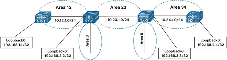
Figure 8-3 Discontiguous Network
Example 8-37 shows that NX-2 and NX-3 appear to have full connectivity to all networks in the OSPF domain. NX-2 maintains connectivity to the 10.34.1.0/24 network and 192.168.4.4/32 network, and NX-3 maintains connectivity to the 10.12.1.0/24 network and 192.168.1.1/32 network.
Example 8-37 Verification of Remote Area Routes on NX-2 and NX-3
10.34.1.0/24, ubest/mbest: 1/0
*via 10.23.1.3, Eth1/2, [110/80], 00:02:56, ospf-NXOS, inter
192.168.1.1/32, ubest/mbest: 1/0
*via 10.12.1.1, Eth1/1, [110/41], 00:04:37, ospf-NXOS, intra
192.168.3.3/32, ubest/mbest: 1/0
*via 10.23.1.3, Eth1/2, [110/41], 00:06:14, ospf-NXOS, inter
192.168.4.4/32, ubest/mbest: 1/0
*via 10.23.1.3, Eth1/2, [110/81], 00:02:35, ospf-NXOS, inter
10.12.1.0/24, ubest/mbest: 1/0
*via 10.23.1.2, Eth1/2, [110/80], 00:07:29, ospf-NXOS, inter
192.168.1.1/32, ubest/mbest: 1/0
*via 10.23.1.2, Eth1/2, [110/81], 00:06:10, ospf-NXOS, inter
192.168.2.2/32, ubest/mbest: 1/0
*via 10.23.1.2, Eth1/2, [110/41], 00:07:29, ospf-NXOS, inter
192.168.4.4/32, ubest/mbest: 1/0
*via 10.34.1.4, Eth1/1, [110/41], 00:04:14, ospf-NXOS, intra
Example 8-38 shows the route tables for NX-1 and NX-4. NX-1 is missing route entries for Area 34, and NX-4 is missing route entries for Area 12. When Area 12’s Type-1 LSAs reach NX-2, NX-2 generates a Type-3 LSA into Area 0 and Area 23. NX-3 receives the Type-3 LSA and inserts it into the LSDB for Area 23. NX-3 does not create a new Type-3 LSA for Area 0 or Area 34.
Example 8-38 Verification of Remote Area Routes on NX-1 and NX-4
10.23.1.0/24, ubest/mbest: 1/0
*via 10.12.1.2, Eth1/1, [110/80], 00:13:12, ospf-NXOS, inter
192.168.2.2/32, ubest/mbest: 1/0
*via 10.12.1.2, Eth1/1, [110/41], 00:13:12, ospf-NXOS, inter
10.23.1.0/24, ubest/mbest: 1/0
*via 10.34.1.3, Eth1/1, [110/80], 00:11:54, ospf-NXOS, inter
192.168.3.3/32, ubest/mbest: 1/0
*via 10.34.1.3, Eth1/1, [110/41], 00:11:54, ospf-NXOS, inter
OSPF ABRs use the following logic for Type-3 LSAs when entering another OSPF Area:
Type-1 LSAs received from a nonbackbone area create Type-3 LSAs into backbone area and nonbackbone areas.
Type-3 LSAs received from Area 0 are created for the nonbackbone area.
Type-3 LSAs received from a nonbackbone area only insert into the LSDB for the source area. ABRs do not create a Type-3 LSA for the other nonbackbone areas.
The simplest fix for a discontiguous network is to install a virtual link between NX-2 and NX-3. Virtual links overcome the ABR limitations by extending Area 0 into a nonbackbone area. It is similar to running a virtual tunnel for OSPF between an ABR and another multi-area OSPF router. The virtual link extends Area 0 across Area 23, making Area 0 a contiguous OSPF area.
The virtual link configuration is applied to the OSPF routing process with the command area area-id virtual-link endpoint-rid. The configuration is applied on both end devices as shown in Example 8-39.
Example 8-39 Virtual Link Configuration
router ospf NXOS
area 0.0.0.23 virtual-link 192.168.3.3
router ospf NXOS
area 0.0.0.23 virtual-link 192.168.2.2
Example 8-40 displays the routing table of NX-1 after the virtual link is configured between NX-2 and NX-3. Notice that the 192.168.4.4 network is present. In addition, the virtual link appears as an OSPF interface.
Example 8-40 Verification of Connectivity After Virtual Link
10.23.1.0/24, ubest/mbest: 1/0
*via 10.12.1.2, Eth1/1, [110/80], 00:22:47, ospf-NXOS, inter
10.34.1.0/24, ubest/mbest: 1/0
*via 10.12.1.2, Eth1/1, [110/120], 00:00:13, ospf-NXOS, inter
192.168.2.2/32, ubest/mbest: 1/0
*via 10.12.1.2, Eth1/1, [110/41], 00:22:47, ospf-NXOS, inter
192.168.3.3/32, ubest/mbest: 1/0
*via 10.12.1.2, Eth1/1, [110/81], 00:00:13, ospf-NXOS, inter
192.168.4.4/32, ubest/mbest: 1/0
*via 10.12.1.2, Eth1/1, [110/121], 00:00:13, ospf-NXOS, inter
OSPF Process ID NXOS VRF default
Total number of interface: 4
Interface ID Area Cost State Neighbors Status
VL1 4 0.0.0.0 40 P2P 1 up
Eth1/1 1 0.0.0.12 40 P2P 1 up
Eth1/2 2 0.0.0.23 40 P2P 1 up
Lo0 3 0.0.0.0 1 LOOPBACK 0 up
Duplicate Router ID
Router IDs (RID) play a critical role for the creation of the topology. If two adjacent routers have the same RID, an adjacency does not form as shown earlier. However, if two routers have the same RID and have an intermediary router, it prevents those routes from being installed in the topology.
The RID act as a unique identifier in the OSPF LSAs. When two different routers advertise LSAs with the same RID, it causes confusion in the OSPF topology, which can result in routes not populating or packets being forwarded toward the wrong router. It also prevent LSA propagation because the receiving router may assume that a loop exists.
Figure 8-4 provides a sample topology in which all Nexus switches are advertising their peering network and their loopback addresses in the 192.168.0.0/16 network space. NX-2 and NX-4 have been configured with the same RID of 192.168.4.4. NX-3 sits between NX-2 and NX-4 and has a different RID, therefore allowing NX-2 and NX-4 to establish full neighbor adjacencies with their peers.
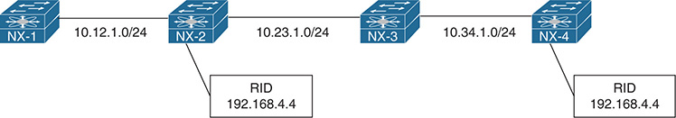
Figure 8-4 Duplicate Router ID Topology
From NX-1’s perspective, the first apparent issue is that NX-4’s loopback interface (192.168.4.4/32) is missing. Example 8-41 displays NX-1’s routing table.
Example 8-41 NX-1’s Routing Table with Missing NX-4’s Loopback Interface
10.23.1.0/24, ubest/mbest: 1/0
*via 10.12.1.2, Eth1/1, [110/80], 2d08h, ospf-NXOS, intra
10.34.1.0/24, ubest/mbest: 1/0
*via 10.12.1.2, Eth1/1, [110/120], 2d08h, ospf-NXOS, intra
192.168.2.2/32, ubest/mbest: 1/0
*via 10.12.1.2, Eth1/1, [110/41], 2d08h, ospf-NXOS, intra
192.168.3.3/32, ubest/mbest: 1/0
*via 10.12.1.2, Eth1/1, [110/81], 2d08h, ospf-NXOS, intra
On NX-2 and NX-4, there are complaints about LSAs and Possible router-id collision syslog messages, as shown in Example 8-42.
Example 8-42 Syslog Messages with LSAs with Duplicate RIDs
05:16:55 NX-4 %OSPF-4-SELF_LSA: ospf-NXOS [8486] context default: Received updated self-originated router LSA. Possible router-id collision
Example 8-43 displays the routing table of the two Nexus switches with the Possible router-id collision syslog messages. Notice that NX-2 is missing NX-1’s loopback interface (192.168.1.1/32) and NX-4’s loopback interface (192.168.4.4/32); whereas NX-4 is missing the 10.12.1.0/24 and NX-2’s loopback interface (192.168.2.2/32) network interface.
Example 8-43 Routing Tables of NX-2 and NX-4
10.34.1.0/24, ubest/mbest: 1/0
*via 10.23.1.3, Eth1/2, [110/80], 2d08h, ospf-NXOS, intra
192.168.1.1/32, ubest/mbest: 1/0
*via 10.12.1.1, Eth1/1, [110/41], 2d08h, ospf-NXOS, intra
192.168.3.3/32, ubest/mbest: 1/0
*via 10.23.1.3, Eth1/2, [110/41], 2d08h, ospf-NXOS, intra
10.23.1.0/24, ubest/mbest: 1/0
*via 10.34.1.3, Eth1/1, [110/80], 2d08h, ospf-NXOS, intra
192.168.3.3/32, ubest/mbest: 1/0
*via 10.34.1.3, Eth1/1, [110/41], 2d08h, ospf-NXOS, intra
A quick check of the RIDs is done by examining the OSPF processes on both Nexus switches that reported the Possible router-id collision using the show ip ospf command. Notice that in Example 8-44, NX-2 and NX-4 have the same RID.
Example 8-44 Syslog Messages with LSAs with Duplicate RIDs
Routing Process NXOS with ID 192.168.4.4 VRF default
Routing Process NXOS with ID 192.168.4.4 VRF default
Remember that the RID can be dynamically set or statically set. Generally, this problem is a result of a configuration being copied from one router to another and not changing the RID. The RID is changed using the command router-id router-id under the OSPF process. The OSPF process restarts upon changing the RID on a Nexus switch.
Filtering Routes
NX-OS provides multiple methods of filtering networks after they are entered into the OSPF database. Filtering of routes occurs on ABRs for internal OSPF networks and ASBRs for external OSPF networks. The following includes some configurations that should be examined when routes are present in one area but not present in a different area.
Area Filtration: Routes are filtered upon receipt or advertisement to an ABR with the process level configuration command area area-id filter-list route-map route-map-name {in|out}.
Route Summarization: Internal routes are summarized on ABRs using the command area area-id range summary-network [not-advertise]. If the not-advertise keyword is configured, a Type-3 LSA is not generated for any of the component routes; thereby hiding them to only the area of origination.
External routes are summarized on ASBRs using the command summary-address summary-network [not-advertise]. The not-advertise keyword stops the generation of any Type-5/Type-7 LSAs for component routes within the summary network.
Note
ABRs for NSSA areas act as an ASBR when the Type 7 LSAs are converted to Type 5 LSA. External summarization is performed only on ABRs when they match this scenario.
Redistribution
Redistributing into OSPF uses the command redistribute [bgp asn | direct | eigrp process-tag | isis process-tag | ospf process-tag | rip process-tag | static] route-map route-map-name. A route-map is required as part of the redistribution process on Nexus switches.
Every protocol provides a seed metric at the time of redistribution that allows the destination protocol to calculate a best path. OSPF uses the following default settings for seed metrics:
The network is configured as an OSPF Type-2 external network.
The default redistribution metric is set to 20 unless the source protocol is BGP which provides a default seed metric of 1.
The default seed metrics can be changed to different values for OSPF external network type (1 versus 2), redistribution metric, and a route-tag if desired.
Example 8-45 provides the necessary configuration to demonstrate the process of redistribution. NX-1 redistributes the connected routes for 10.1.1.0/24 and 10.11.11.0/24 in lieu of them being advertised with the OSPF routing protocol. Notice that the route-map can be a simple permit statement without any conditional matches.
Example 8-45 NX-1 Redistribution Configuration
redistribute direct route-map REDIST
!
route-map REDIST permit 10
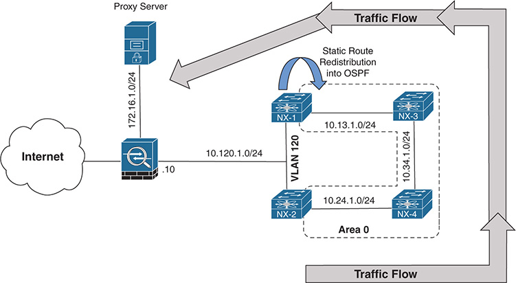
OSPF Forwarding Address
OSPF Type-5 LSAs include a field known as the forwarding address that optimizes forwarding traffic when the source uses a shared network segment. The forwarding address scenario defined in RFC 2328 is not common, but Figure 8-5 provides a sample topology. The following is included in this topology:
OSPF is enabled on all the links in Area 0 (10.13.1.0/24, 10.24.1.0/24, and 10.34.1.0/24).
Users are trying to connect to the proxy server that is located in a DMZ (172.16.1.1) off of the firewall.
NX-1 has a static route for the 172.16.1.0/24 network pointing toward the firewall (10.120.1.10).
NX-1 is redistributing the route into OSPF as a Type-1 External route.
NX-1 and NX-2 have direct connectivity using VLAN 120 (10.120.1.0/24) to the firewall.
Figure 8-5 Default OSPF Forwarding Address
Example 8-46 displays NX-1’s configuration for advertising the 172.16.1.0/24 network into the OSPF domain. In addition, NX-1’s static route is verified for installation into the OSPF database and is then checked on NX-3.
Example 8-46 NX-1 Configuration to Redistribute 172.16.1.0/24 into OSPF
ip route 172.16.1.0/24 10.120.1.10
!
route-map REDIST permit 10
set metric-type type-1
!
router ospf NXOS
redistribute static route-map REDIST
log-adjacency-changes
!
interface Ethernet1/1
ip router ospf NXOS area 0.0.0.0
*via 10.13.1.1, Eth2/1, [0/0], 00:09:19, direct
..
10.120.1.0/24, ubest/mbest: 1/0, attached
*via 10.120.1.1, Eth2/9, [0/0], 00:09:15, direct
..
172.16.1.0/24, ubest/mbest: 1/0
*via 10.34.1.4, Eth2/2, [110/80], 00:09:57, ospf-NXOS, intra
Example 8-47 displays the Type-5 LSA for the external route for the 172.16.1.0/24 network to the proxy server. The ASBR is identified as NX-1 (192.168.1.1), which is the device that all Nexus switches forward packets to in order to reach the 172.16.1.0/24 network. Notice that the forwarding address is the default value of 0.0.0.0.
Example 8-47 Default FA in OSPF Type-5 LSA
OSPF Router with ID (192.168.4.4) (Process ID NXOS VRF default)
Type-5 AS External Link States
LS age: 199
Options: 0x2 (No TOS-capability, No DC)
LS Type: Type-5 AS-External
Link State ID: 172.16.1.0 (Network address)
Advertising Router: 192.168.1.1
LS Seq Number: 0x80000002
Checksum: 0x7c98
Length: 36
Network Mask: /24
Metric Type: 1 (Same units as link state path)
TOS: 0
Metric: 20
Forward Address: 0.0.0.0
External Route Tag: 0
Routing Process NXOS with ID 192.168.1.1 VRF default
Traffic from NX-2 (and NX-4) takes the non-optimal route (NX-2→NX-4→NX-3→ NX-1→FW), as shown in Example 8-48. The optimal route would allow NX-2 to use the directly connected 10.120.1.0/24 network toward the firewall.
Example 8-48 Verification of Suboptimal Routing
traceroute to 172.16.1.1 (172.16.1.1), 30 hops max, 40 byte packets
1 10.24.1.4 (10.24.1.4) 1.402 ms 1.369 ms 1.104 ms
2 10.34.1.3 (10.34.1.3) 2.886 ms 2.846 ms
3 10.13.1.1 (10.13.1.1) 4.052 ms 3.527 ms 3.659 ms
4 10.120.1.10 (10.120.1.10) 5.221 ms *
NX-4# trace 172.16.1.1
traceroute to 172.16.1.1 (172.16.1.1), 30 hops max, 40 byte packets
1 10.34.1.3 (10.34.1.3) 1.485 ms 1.29 ms 1.18 ms
2 10.13.1.1 (10.13.1.1) 2.385 ms 2.34 ms 2.478 ms
3 10.120.1.10 (10.120.1.10) 3.856 ms * *
The forwarding address in OSPF Type-5 LSAs is specified in RFC 2328 for scenarios such as this. When the forwarding address is 0.0.0.0, all routers forward packets to the ASBR, introducing the potential for suboptimal routing.
The OSPF forwarding address changes from 0.0.0.0 to the next-hop IP address in the source routing protocol when the following occurs:
OSPF is enabled on the ASBR’s interface that points to the next-hop IP address. In this scenario, NX-1’s VLAN120 interface has OSPF enabled, which correlates to the 172.16.1.0/24 static route’s next-hop address of 10.120.1.10.
That interface is not set to passive.
That interface is a broadcast or nonbroadcast OSPF network type.
Now OSPF is enabled on the NX-1’s and NX-2’s VLAN120 interface, which has been associated to area 120. Figure 8-6 illustrates the current topology. VLAN interfaces default to the broadcast OSPF network type, and all conditions were met to set the FA to an explicit IP address.
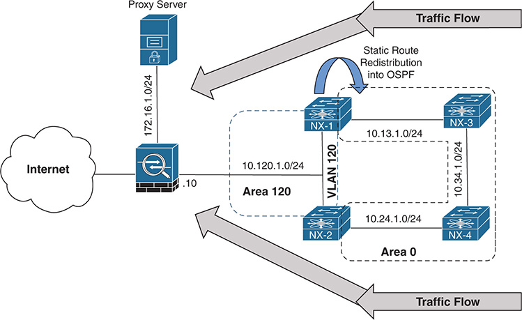
Figure 8-6 OSPF Forwarding Address Nondefault
Example 8-49 displays the Type-5 LSA for the 172.16.1.0/24 network. Now that OSPF is enabled on NX-1’s 10.120.1.1 interface and the interface is a broadcast network type, the forwarding address changed from 0.0.0.0 to 10.120.1.10.
Example 8-49 Viewing the Nondefault OSPF Forwarding Address
OSPF Router with ID (192.168.2.2) (Process ID NXOS VRF default)
Type-5 AS External Link States
LS Type: Type-5 AS-External
Link State ID: 172.16.1.0 (Network address)
Advertising Router: 192.168.1.1
Network Mask: /24
Metric Type: 1 (Same units as link state path)
TOS: 0
Metric: 20
Forward Address: 10.120.1.10
External Route Tag: 0
Example 8-50 verifies that connectivity from NX-2 and NX-4 now takes the optimal path because the forwarding address changed to 10.120.1.10.
Example 8-50 Verification of Optimal Routing
traceroute to 172.16.1.1 (172.16.1.1), 30 hops max, 40 byte packets
1 10.120.1.10 (10.120.1.10) 2.845 ms * 3.618 ms
traceroute to 172.16.1.1 (172.16.1.1), 30 hops max, 40 byte packets
1 10.24.1.2 (10.24.1.2) 1.539 ms 1.288 ms 1.071 ms
2 10.120.1.10 (10.120.1.10) 3.4 ms * 3.727 ms
A junior network engineer identified that the 10.120.1.0/24 network is no longer needed. The engineer implemented filtering on Area 120 LSAs from being advertised into Area 0, as shown in Example 8-51.
Example 8-51 Configuration to Filter 10.120.1.10 Network in OSPF
router ospf NXOS
redistribute static route-map REDIST
router ospf NXOS
After the junior network engineer made the change, the 172.16.1.0/24 network disappeared on all the routers in Area 0. Only the other peering network is present, as shown in Example 8-52.
Example 8-52 Verification of Missing 172.16.1.0/24 Network
10.24.1.0/24, ubest/mbest: 1/0
*via 10.34.1.4, Eth1/2, [110/80], 00:23:31, ospf-NXOS, intra
10.13.1.0/24, ubest/mbest: 1/0
*via 10.34.1.3, Eth1/2, [110/80], 00:23:42, ospf-NXOS, intra
If the Type-5 LSA forwarding address is not a default value, the address must be an intra-area or inter-area OSPF route. If the FA is not resolved, the LSA is ignored and does not install into the RIB. The FA provides a mechanism to introduce multiple paths to the external next-hop address. Otherwise, there is not a reason to include the FA in the LSA. Removing the filtering on NX-1 and NX-2 restores connectivity.
Note
In the scenario provided, there was not any redundancy to provide connectivity in the event that NX-1 failed. Typically, the configuration is repeated on other routers, which provides resiliency. Be considerate of the external networks when applying filtering of routes on ABRs.
Troubleshooting OSPF Path Selection
OSPF executes Dijkstra’s Shortest Path First (SPF) algorithm to create a loop-free topology of shortest paths. All routers use the same logic to calculate the shortest path for each network. Path selection prioritizes paths by using the following order of path selection:
Intra-Area
Inter-Area
External Type-1
External Type-2
The following sections explain each component in detail.
Intra-Area Routes
Routes advertised via a Type-1 LSA for an Area are always preferred over Type-3 and Type-5 LSAs. If multiple intra-area routes exist, the path with the lowest total path metric is installed in the RIB. If there is a tie in metric, both routes install into the RIB.
Note
Even if the path metric from an intra-area route is higher than an inter-area path metric; the intra-area path is selected.
Inter-Area Routes
Inter-area routes take the lowest total path metric to the destination. If there is a tie in metric, both routes install into the RIB. All inter-area paths for a route must go through Area 0.
In Figure 8-7, NX-1 is computing the path to NX-6. NX-1 uses the path NX-1→ NX-3→NX-5→NX-6 because its total path metric is 35 versus the NX-1→NX-2→ NX-4→NX-6 path with a metric of 40.
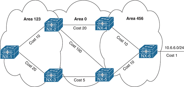
Figure 8-7 Inter-Area Route Selection
External Route Selection
Earlier in this chapter, OSPF external routes were briefly explained as Type-1 or Type-2. The main differences between Type-1 and Type-2 external OSPF routes include the following:
Type-1 routes are preferred over Type-2.
The Type-1 path metric equals the following: redistribution metric + total path metric to reach the ASBR.
The Type-2 path metrics equals only the redistribution metric.
Another critical factor to identify is whether the devices are operating in RFC 1583 or RFC 2328 mode. Cisco NX-OS switches operate in 2328 mode by default, whereas Cisco IOS, IOS XE, and IOS XR operate only in 1583 mode. The following subsection explains the path selection logic depending on whether the device is operating in RFC 1583 or RFC 2328 mode.
E1 and N1 External Routes
The following are the differences in path selection for OSPF External Type-1 routes:
RFC 1583 Mode: External OSPF Type-1 route calculation uses the redistribution metric + the lowest path metric to reach the ASBR that advertised the network. Type-1 path metrics are lower for routers closer to the originating ASBR, whereas generally the path metric is higher for a router 10 hops away from the ASBR.
If there is a tie in the path metric, both routes install into the RIB. If the ASBR is in a different area, the path of the traffic must go through Area 0. An ABR router does not install an O E1 and O N1 route into the RIB at the same time. O N1 is given preference for a typical NSSA area and prevents the O E1 from installing on the ABR.
RFC 2328 Mode: Preference first goes to the ASBR in the same area as the calculating router. In the event that the ASBR is not in the same area as the calculating router, the rules for calculating the best path follow those as RFC 1583 Mode.
Note
There is an option with NSSA areas that prevents the redistributed routes from being advertised outside of the NSSA area (setting the P-bit to zero), which may change the behavior. This concept is outside of the scope of this book; it is explained in depth in RFC 2328 and 3101.
Figure 8-8 shows the topology for NX-1 and NX-3 computing a path to the external network (100.65.0.0/16) that is being redistributed on NX-6 and NX7.
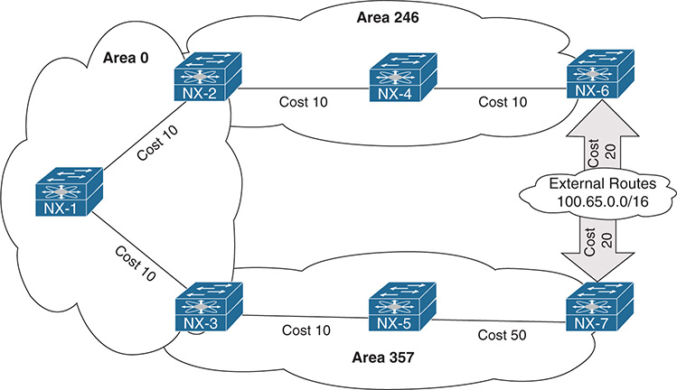
Figure 8-8 External Type-2 Route Selection Topology
The path NX-1→NX-2→NX-4→NX-6 has a metric of 50, which is less than the path NX-1→NX-3→NX-5→NX-7, which has a path metric of 90. NX-1 selects the NX-1→NX-2→NX-4→NX-6 path to reach the 100.65.0.0/16 network, whereas NX-3 selects the NX-3→NX-5→NX-7 path that has a higher metric.
The decisions were made based upon RFC 2328 logic because NX-1 is not in an area with an ASBR, whereas NX-3 is in the same area as NX-7. Example 8-53 displays the routing tables and path metrics from NX-1 and NX-3’s perspective.
Example 8-53 External OSPF Path Selection for Type-1 Networks
100.65.0.0/16, ubest/mbest: 1/0
*via 10.12.1.2, Eth1/1, [110/50], 00:33:55, ospf-NXOS, type-1
100.65.0.0/16, ubest/mbest: 1/0
*via 10.35.1.5, Eth1/1, [110/80], 00:00:15, ospf-NXOS, type-1
E2 and N2 External Routes
Here are the differences in path selection for OSPF External Type-2 routes:
RFC 1583 Mode: External OSPF Type-2 routes do not increment in metric respective of the path metric to the ASBR. If there is a tie in the redistribution metric, the router compares the forwarding cost. The forwarding cost is the metric to the ASBR that advertised the network, and the lower forwarding cost is preferred. If there is a tie in forwarding cost, both routes install into the routing table. An ABR router does not install an O E2 and O N2 route into the RIB at the same time. O N2 is given preference for a typical NSSA area and prevents the O E2 from installing on the ABR.
RFC 2328 Mode: Preference first goes to the ASBR in the same area as the calculating router. In the event that the ASBR is not in the same area as the calculating router, the rules for calculating the best path follow those as RFC 1583 Mode.
Reusing the topology from Figure 8-6, all paths reflect a metric of 20. The first deciding step is to check to see if the ASBR for the 100.65.0.0/16 network is in the same area as the ASBR. NX-1 is not, so it selects the path based on forwarding cost. Forwarding cost is calculated on NX-OS.
Example 8-54 walks through the steps for calculating the forwarding cost.
Step 1. The ASBRs must be identified by looking at the OSPF LSDB with the command show ip ospf database external network.
Step 2. The metric reported by the ABR for the ASBR address (Type-4 LSA) is examined with the command show ip ospf database asbr-summary detail. (This provides the path metric from the ASBR to the area’s ABR.)
Step 3. Find the metric to the ABR of the Type-4 LSA with the command show ip ospf database router abr-ip-address detail.
Step 4. Combine the two metrics to calculate a forwarding cost of 30 from NX-1 to NX-6, and a forwarding cost of 70 from NX-1 to NX-7. The path to NX-6 is the lowest and is selected by NX-1.
Example 8-54 NX-1 External OSPF Path Selection for Type-2 Network
100.65.0.0/16, ubest/mbest: 1/0
*via 10.12.1.2, Eth1/1, [110/20], 00:04:33, ospf-NXOS, type-2
OSPF Router with ID (192.168.1.1) (Process ID NXOS VRF default)
Type-5 AS External Link States
Link ID ADV Router Age Seq# Checksum Tag
100.65.0.0 192.168.6.6 31 0x80000002 0x277b 0
100.65.0.0 192.168.7.7 375 0x80000002 0x1a86 0
OSPF Router with ID (192.168.1.1) (Process ID NXOS VRF default)
Link State ID: 192.168.6.6 (AS Boundary Router address)
TOS: 0 Metric: 20
Link State ID: 192.168.7.7 (AS Boundary Router address)
TOS: 0 Metric: 60
OSPF Router with ID (192.168.1.1) (Process ID NXOS VRF default)
Router Link States (Area 0.0.0.0)
LS Type: Router Links
Advertising Router: 192.168.2.2
Link connected to: a Router (point-to-point)
(Link ID) Neighboring Router ID: 192.168.1.1
(Link Data) Router Interface address: 10.12.1.2
TOS 0 Metric: 10
TOS 0 Metric: 10
OSPF Router with ID (192.168.1.1) (Process ID NXOS VRF default)
Router Link States (Area 0.0.0.0)
LS Type: Router Links
Advertising Router: 192.168.3.3
Link connected to: a Router (point-to-point)
(Link ID) Neighboring Router ID: 192.168.1.1
(Link Data) Router Interface address: 10.13.1.3
TOS 0 Metric: 10
TOS 0 Metric: 10
NX-3’s path is selected based on RFC 2328’s guidelines because NX-3 is in the same area as NX-7. Example 8-55 confirms the path from NX-3 → NX-5 → NX-7.
Example 8-55 NX-3 External OSPF Path Selection for Type-2 Network
100.65.0.0/16, ubest/mbest: 1/0
*via 10.35.1.5, Eth1/1, [110/80], 00:00:15, ospf-NXOS, type-1
Problems with Intermixed RFC 1583 and RFC 2328 Devices
RFC 2328 logic is generally sufficient for finding the next-hop for external routes, but it could lead to suboptimal paths (as shown in the previous section) or cause routing loops when combined with devices that do not use RFC 2328 logic. Figure 8-9 displays a sample topology that creates a routing loop because IOS routers operate with RFC 1583 logic.
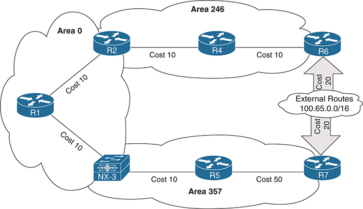
Figure 8-9 External Type-2 Route Selection with Nexus and IOS Devices
NX-3 selects R7 as the ASBR for the 100.65.0.0/16 network using RFC 2328 standards and forwards packets toward R5. R5 uses RFC 1583 standards and forwards packets back to NX-3, causing a loop. Example 8-56 verifies that the loop exists using a simple traceroute from NX-3 toward the 100.65.0.0/16 network.
Example 8-56 Routing Loop Because of Intermixed OSPF Devices
traceroute to 100.65.1.1 (100.65.1.1), 30 hops max, 40 byte packets
1 10.35.1.5 (10.35.1.5) 1.819 ms 1.124 ms 0.982 ms
2 10.35.1.3 (10.35.1.3) 1.9 ms 1.459 ms 1.534 ms
3 10.35.1.5 (10.35.1.5) 2.427 ms 2.214 ms 2.111 ms
The solution involves placing the Nexus switches into RFC 1583 mode with the OSPF command rfc1583compatibility. Example 8-57 displays the configuration to remove the routing loop.
Example 8-57 Verification of RFC1583 Compatibility
rfc1583compatibility
Note
Another significant change between RFC 1583 and RFC 2328 is the summarization metric. With RFC 1583, an ABR uses the lowest metric from any of the component routes for the metric of the summarized network. RFC 2328 uses the highest metric from any of the component routes for the metric of the summarized route. Deploying rfc1583compatibility on the ABR changes the behavior.
Interface Link Costs
Interface cost is essential component for Dijkstra’s SPF calculation because the shortest path metric is based on the cumulative interface cost (metric) from the router to the destination. OSPF assigns the OSPF link cost (metric) for an interface using the following formula:
Cost = Interface Bandwidth/Reference Bandwidth
The default reference bandwidth for NX-OS is 40 Gbps, whereas for other Cisco OSs (IOS and IOS XR) it is 100 Mbps. Table 8-9 provides the OSPF cost for common network interface types using the default reference bandwidth.
Table 8-9 OSPF Interface Costs Using Default Settings
Interface Type |
Default NX-OS OSPF Cost |
Default IOS OSPF Cost |
T1 |
N/A |
64 |
Ethernet |
4000 |
10 |
FastEthernet |
400 |
1 |
GigabitEthernet |
40 |
1 |
10-GigabitEthernet |
4 |
1 |
40-GigabitEthernet |
1 |
1 |
100-GigabitEthernet |
1 |
1 |
Notice in Table 8-9 that there is no differentiation in the link cost associated to a FastEthernet interface and a 100-Gigabit Ethernet interface on IOS routers. This can result in suboptimal path selection and is magnified when a NX-OS switch is inserted into a path.
Figure 8-10 displays a topology that introduces problems because of the reference bandwidth not being set properly. Connectivity between the two WAN service providers should take the 10 Gigabit Path (R1→NX-3→NX-4→R2) and use the 1 Gigabit link between R1 and R2 only as a backup path, because traffic is likely be dropped by the QoS policy to support only business-critical traffic.
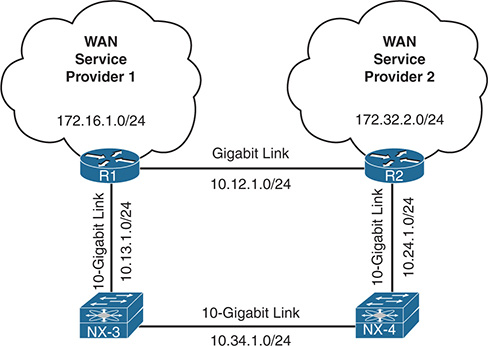
Figure 8-10 Topology to Demonstrate Problems with Reference Bandwidth
Example 8-58 displays the routing table of R1 with the default reference bandwidth. Traffic between 172.16.1.0/24 and 172.32.2.0/24 flows across the backup 1 Gigabit link (10.12.1.0/24), which does not follow the intended traffic patterns. Notice that the OSPF path metric is 2 to the 172.32.2.0/24 network using the 1 Gigabit link.
Example 8-58 R1’s Routing Table with Default OSPF Auto-Cost Bandwidth
Gateway of last resort is not set
10.0.0.0/8 is variably subnetted, 6 subnets, 2 masks
10.24.1.0/24 [110/2] via 10.12.1.2, 00:10:24, GigabitEthernet0/1
10.34.1.0/24 [110/5] via 10.13.1.3, 00:10:09, TenGigabitEthernet1/2
172.32.0.0/24 is subnetted, 1 subnets
172.32.2.0 [110/2] via 10.12.1.2, 00:03:20, GigabitEthernet0/1
Now let’s shut down the 1 Gigabit link and examine the OSPF metrics using the 10 Gigabit path. Example 8-59 displays the process. Notice that R1’s path metric is 10 to the 172.32.2.0/24 network using the 10 Gigabit link path.
Example 8-59 R1’s Routing Table with 1 Gigabit Link Shutdown
Enter configuration commands, one per line. End with CNTL/Z.
R1(config)# int gi0/1
R1(config-if)# shut
16:04:43.107: %OSPF-5-ADJCHG: Process 1, Nbr 192.168.2.2 on GigabitEthernet0/1 from FULL to DOWN, Neighbor Down: Interface down or detached
16:04:45.077: %LINK-5-CHANGED: Interface GigabitEthernet0/1, changed state to administratively down
16:04:46.077: %LINEPROTO-5-UPDOWN: Line protocol on Interface GigabitEthernet0/1, changed state to down
R1(config-if)# do show ip route ospf | b Gatewa
Gateway of last resort is not set
10.0.0.0/8 is variably subnetted, 5 subnets, 2 masks
10.12.1.0/24 [110/10] via 10.13.1.3, 00:00:09, TenGigabitEthernet1/2
10.24.1.0/24 [110/9] via 10.13.1.3, 00:00:09, TenGigabitEthernet1/2
10.34.1.0/24 [110/5] via 10.13.1.3, 00:11:40, TenGigabitEthernet1/2
172.32.0.0/24 is subnetted, 1 subnets
172.32.2.0 [110/10] via 10.13.1.3, 00:00:09, TenGigabitEthernet1/2
R1 and R2 are taking the suboptimal path because of the differences in reference bandwidth. Change the reference bandwidth to match the NX-OS’s default setting of 40 Gbps. The reference bandwidth on IOS and NX-OS devices is set with the command auto-cost reference-bandwidth speed-in-megabits. Example 8-60 displays the reference bandwidth being changed on R1 and R2.
Example 8-60 Changing of OSPF Reference Bandwidth on R1 and R2
R1(config-router)# auto-cost reference-bandwidth ?
<1-4294967> The reference bandwidth in terms of Mbits per second
R1(config-router)# auto-cost reference-bandwidth 40000
% OSPF: Reference bandwidth is changed.
Please ensure reference bandwidth is consistent across all routers.
Enter configuration commands, one per line. End with CNTL/Z.
R2(config)# router ospf 1
R2(config-router)# auto-cost reference-bandwidth 40000
% OSPF: Reference bandwidth is changed.
Please ensure reference bandwidth is consistent across all routers.
Now let’s examine the new OSPF metric cost using the 10 Gigabit path, and then reactivate the 1 Gigabit link on R1. Example 8-61 demonstrates this change and then verifies which path is now used to connect the 172.16.1.0/24 and 172.32.2.0/24 networks.
Example 8-61 Verification of New Path After New Reference OSPF Bandwidth Is Configured on R1 and R2
Gateway of last resort is not set
10.0.0.0/8 is variably subnetted, 5 subnets, 2 masks
10.12.1.0/24 [110/13] via 10.13.1.3, 00:01:55, TenGigabitEthernet1/2
10.24.1.0/24 [110/12] via 10.13.1.3, 00:01:55, TenGigabitEthernet1/2
10.34.1.0/24 [110/8] via 10.13.1.3, 00:01:55, TenGigabitEthernet1/2
172.32.0.0/24 is subnetted, 1 subnets
172.32.2.0 [110/13] via 10.13.1.3, 00:01:55, TenGigabitEthernet1/2
Enter configuration commands, one per line. End with CNTL/Z.
R1(config)# int gi0/1
R1(config-if)# no shut
16:09:10.887: %LINK-3-UPDOWN: Interface GigabitEthernet0/1, changed state to up
16:09:11.887: %LINEPROTO-5-UPDOWN: Line protocol on Interface GigabitEthernet0/1, changed state to up
16:09:16.623: %OSPF-5-ADJCHG: Process 1, Nbr 192.168.2.2 on GigabitEthernet0/1 from LOADING to FULL, Loading Done
R1(config-if)# do show ip route ospf | b Gate
Gateway of last resort is not set
10.0.0.0/8 is variably subnetted, 6 subnets, 2 masks
10.24.1.0/24 [110/12] via 10.13.1.3, 00:02:46, TenGigabitEthernet1/2
10.34.1.0/24 [110/8] via 10.13.1.3, 00:02:46, TenGigabitEthernet1/2
172.32.0.0/24 is subnetted, 1 subnets
172.32.2.0 [110/13] via 10.13.1.3, 00:02:46, TenGigabitEthernet1/2
The path between 172.16.1.0/24 and 172.32.2.0/24 continues to use the 10 Gigabit path because the path metric cost using the 1 Gigabit path would be 41 ((1,000/40,000) + 1 (for loopback).
Note
Another solution involves statically setting the OSPF cost on an interface with the command ip ospf cost 1-65535 for NX-OS and IOS devices.
Summary
This chapter provided a brief review of the OSPF routing protocols, and then explored the methods for troubleshooting adjacency issues between devices, missing routes, and path selection.
The following parameters must be compatible for the two routers to become neighbors:
Interfaces must be Active.
Connectivity between devices must exist using the primary subnet.
MTU matches between devices.
Router-IDs are unique.
Interface Area must match.
Need for Designated Router matches based on OSPF network types.
OSPF stub area flags match.
OSPF is a link state routing protocol that builds a complete map based on LSAs. Routes are missing from the OSPF routing domain typically because of bad network design or through filtering of routes as they are advertised across area boundaries. This chapter provided some common bad OSPF designs that cause loss of path information.
OSPF builds a loop-free topology from the computing router to all destination networks. All routers use the same logic to calculate the shortest-path for each network. Path selection prioritizes paths by using the following logic:
Intra-Area
Inter-Area
External Type-1
External Type-2
When the redistribution metric is the same, Nexus switches select external paths using RFC 2328 by default, which states to prefer intra-area connectivity over inter-area connectivity when multiple ABSRs are present. Cisco IOS and IOS XR routers use RFC 1583 external path selection, which selects an ABSR by the lowest forwarding cost. This can cause routing loops when Nexus switches are intermixed with IOS or IOS XR routers, but the Nexus switches can be placed in RFC 1583 compatibility mode.
References
RFC 1583, OSPF Version 2. IETF, http://www.ietf.org/rfc/rfc1583.txt, March 1997.
RFC 2328, OSPF Version 2. IETF, http://www.ietf.org/rfc/rfc2328.txt, April 1998.
Edgeworth, Brad, Aaron Foss, Ramiro Garza Rios. IP Routing on Cisco IOS, IOS XE and IOS XR. Indianapolis: Cisco Press, 2014.
Cisco. Cisco NX-OS Software Configuration Guides, http://www.cisco.com.