Chapter 3. Fundamentals of WANs and IP Routing
This chapter covers the following exam topics:
1.0 Network Fundamentals
1.1 Explain the role and function of network components
1.1.a Routers
1.2 Describe characteristics of network topology architectures
1.2.d WAN
This chapter introduces WANs and the various features of the TCP/IP network layer.
First, for WANs, note that the current CCNA blueprint does not examine WANs in detail as an end to themselves. However, to understand IP routing, you need to understand the basics of the two types of WAN links introduced in the first major section of this chapter: serial links and Ethernet WAN links. In their most basic form, these WAN links connect routers that sit at sites that can be miles to hundreds of miles apart, allowing communications between remote sites.
The rest of the chapter then turns to the TCP/IP Network layer, with IP as the center of the discussion. The second section of the chapter discusses the major features of IP: routing, addressing, and routing protocols. The final section of the chapter examines a few protocols other than IP that also help the TCP/IP Network layer create a network that allows end-to-end communication between endpoints.
“Do I Know This Already?” Quiz
Take the quiz (either here or use the PTP software) if you want to use the score to help you decide how much time to spend on this chapter. The letter answers are listed at the bottom of the page following the quiz. Appendix C, found both at the end of the book as well as on the companion website, includes both the answers and explanations. You can also find both answers and explanations in the PTP testing software.
Table 3-1 “Do I Know This Already?” Foundation Topics Section-to-Question Mapping
Foundation Topics Section |
Questions |
|---|---|
Wide-Area Networks |
1, 2 |
IP Routing |
3–6 |
Other Network Layer Functions |
7 |
1. Which of the following fields in the HDLC header used by Cisco routers does Cisco add, beyond the ISO standard HDLC?
a. Flag
b. Type
c. Address
d. FCS
2. Two routers, R1 and R2, connect using an Ethernet over MPLS service. The service provides point-to-point service between these two routers only, as a Layer 2 Ethernet service. Which of the following are the most likely to be true about this WAN? (Choose two answers.)
a. R1 will connect to a physical Ethernet link, with the other end of the cable connected to R2.
b. R1 will connect to a physical Ethernet link, with the other end of the cable connected to a device at the WAN service provider point of presence.
c. R1 will forward data-link frames to R2 using an HDLC header/trailer.
d. R1 will forward data-link frames to R2 using an Ethernet header/trailer.
3. Imagine a network with two routers that are connected with a point-to-point HDLC serial link. Each router has an Ethernet, with PC1 sharing the Ethernet with Router1 and PC2 sharing the Ethernet with Router2. When PC1 sends data to PC2, which of the following is true?
a. Router1 strips the Ethernet header and trailer off the frame received from PC1, never to be used again.
b. Router1 encapsulates the Ethernet frame inside an HDLC header and sends the frame to Router2, which extracts the Ethernet frame for forwarding to PC2.
c. Router1 strips the Ethernet header and trailer off the frame received from PC1, which is exactly re-created by Router2 before forwarding data to PC2.
d. Router1 removes the Ethernet, IP, and TCP headers and rebuilds the appropriate headers before forwarding the packet to Router2.
4. Which of the following does a router normally use when making a decision about routing TCP/IP packets?
a. Destination MAC address
b. Source MAC address
c. Destination IP address
d. Source IP address
e. Destination MAC and IP addresses
5. Which of the following are true about a LAN-connected TCP/IP host and its IP routing (forwarding) choices?
a. The host always sends packets to its default gateway.
b. The host never sends packets to its default gateway.
c. The host sends packets to its default gateway if the destination IP address is in a different subnet than the host.
d. The host sends packets to its default gateway if the destination IP address is in the same subnet as the host.
6. Which of the following are functions of a routing protocol? (Choose two answers.)
a. Advertising known routes to neighboring routers
b. Learning routes for subnets directly connected to the router
c. Learning routes and putting those routes into the routing table for routes advertised to the router by its neighboring routers
d. Forwarding IP packets based on a packet’s destination IP address
7. A company implements a TCP/IP network, with PC1 sitting on an Ethernet LAN. Which of the following protocols and features requires PC1 to learn information from some other server device?
a. ARP
b. ping
c. DNS
d. None of these answers is correct.
Answers to the “Do I Know This Already?” quiz:
1 B
2 B, D
3 A
4 C
5 C
6 A, C
7 C
Foundation Topics
Wide-Area Networks
Imagine a typical day at the branch office at some enterprise. The user sits at some endpoint device: a PC, tablet, phone, and so on. It connects to a LAN, either via an Ethernet cable or using a wireless LAN. However, the user happens to be checking information on a website, and that web server sits at the home office of the company. To make that work, the data travels over one or more wide-area network (WAN) links.
WAN technologies define the physical (Layer 1) standards and data-link (Layer 2) protocols used to communicate long distances. This first section examines two such technologies: leased-line WANs and Ethernet WANs. Leased-line WANs have been an option for networks for half a century, are becoming much less common today, but you may still see some leased-line WAN links in the exam. Ethernet WAN links do use the same data-link protocols as Ethernet LANs, but they use additional features to make the links work over the much longer distances required for WANs. The next few pages examine leased-line WANs first, followed by Ethernet WANs.
Leased-Line WANs
To connect LANs using a WAN, the internetwork uses a router connected to each LAN, with a WAN link between the routers. First, the enterprise’s network engineer would order some kind of WAN link. A router at each site connects to both the WAN link and the LAN, as shown in Figure 3-1. Note that a crooked line between the routers is the common way to represent a leased line when the drawing does not need to show any of the physical details of the line.

Figure 3-1 Small Enterprise Network with One Leased Line
This section begins by examining the physical details of leased lines, followed by a discussion of the default data-link protocol for leased lines (HDLC).
Physical Details of Leased Lines
The leased line service delivers bits in both directions, at a predetermined speed, using full-duplex logic. In fact, conceptually it acts as if you had a full-duplex crossover Ethernet link between two routers, as shown in Figure 3-2. The leased line uses two pairs of wires, one pair for each direction of sending data, which allows full-duplex operation.
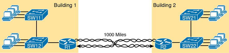
Figure 3-2 Conceptual View of the Leased-Line Service
Of course, leased lines have many differences compared to an Ethernet crossover cable. To create such possibly long links, or circuits, a leased line does not actually exist as a single long cable between the two sites. Instead, the telephone company (telco) that creates the leased line installs a large network of cables and specialized switching devices to create its own computer network. The telco network creates a service that acts like a crossover cable between two points, but the physical reality is hidden from the customer.
Leased lines come with their own set of terminology as well. First, the term leased line refers to the fact that the company using the leased line does not own the line but instead pays a monthly lease fee to use it. Table 3-2 lists some of the many names for leased lines, mainly so that in a networking job, you have a chance to translate from the terms each person uses with a basic description as to the meaning of the name.
Table 3-2 Different Names for a Leased Line
Name |
Meaning or Reference |
|---|---|
Leased circuit, Circuit |
The words line and circuit are often used as synonyms in telco terminology; circuit makes reference to the electrical circuit between the two endpoints. |
Serial link, Serial line |
The words link and line are also often used as synonyms. Serial in this case refers to the fact that the bits flow serially and that routers use serial interfaces. |
Point-to-point link, Point-to-point line |
These terms refer to the fact that the topology stretches between two points, and two points only. (Some older leased lines allowed more than two devices.) |
T1 |
This specific type of leased line transmits data at 1.544 megabits per second (1.544 Mbps). |
WAN link, Link |
Both of these terms are very general, with no reference to any specific technology. |
Private line |
This term refers to the fact that the data sent over the line cannot be copied by other telco customers, so the data is private. |
To create a leased line, some physical path must exist between the two routers on the ends of the link. The physical cabling must leave the customer buildings where each router sits. However, the telco does not simply install one cable between the two buildings. Instead, it uses what is typically a large and complex network that creates the appearance of a cable between the two routers.
Figure 3-3 gives a little insight into the cabling that could exist inside the telco for a short leased line. Telcos put their equipment in buildings called central offices (CO). The telco installs cables from the CO to most every other building in the city, expecting to sell services to the people in those buildings one day. The telco would then configure its switches to use some of the capacity on each cable to send data in both directions, creating the equivalent of a crossover cable between the two routers.

Figure 3-3 Possible Cabling Inside a Telco for a Short Leased Line
Although the customer does not need to know all the details of how a telco creates a particular leased line, enterprise engineers do need to know about the parts of the link that exist inside the customer’s building at the router. However, for the purposes of CCNA, you can think of any serial link as a point-to-point connection between two routers.
HDLC Data-Link Details of Leased Lines
A leased line provides a Layer 1 service. In other words, it promises to deliver bits between the devices connected to the leased line. However, the leased line itself does not define a data-link layer protocol to be used on the leased line.
Because leased lines define only the Layer 1 transmission service, many companies and standards organizations have created data-link protocols to control and use leased lines. Today, the two most popular data-link layer protocols used for leased lines between two routers are High-Level Data Link Control (HDLC) and Point-to-Point Protocol (PPP).
All data-link protocols perform a similar role: to control the correct delivery of data over a physical link of a particular type. For example, the Ethernet data-link protocol uses a destination address field to identify the correct device that should receive the data and an FCS field that allows the receiving device to determine whether the data arrived correctly. HDLC provides similar functions.
HDLC has less work to do than Ethernet because of the simple point-to-point topology of a leased line. When one router sends an HDLC frame, the frame can go only one place: to the other end of the link. So, while HDLC has an address field, the destination is implied, and the actual address is unimportant. The idea is sort of like when I have lunch with my friend Gary, and only Gary. I do not need to start every sentence with “Hey, Gary”—he knows I am talking to him.
HDLC has other fields and functions similar to Ethernet as well. Table 3-3 lists the HDLC fields, with the similar Ethernet header/trailer field, just for the sake of learning HDLC based on something you have already learned about (Ethernet).
Table 3-3 Comparing HDLC Header Fields to Ethernet
HDLC Field |
Ethernet Equivalent |
Description |
|---|---|---|
Flag |
Preamble, SFD |
Lists a recognizable bit pattern so that the receiving nodes realize that a new frame is arriving. |
Address |
Destination Address |
Identifies the destination device. |
Control |
N/A |
Mostly used for purposes no longer in use today for links between routers. |
Type |
Type |
Identifies the type of Layer 3 packet encapsulated inside the frame. |
FCS |
FCS |
Identifies a field used by the error detection process. (It is the only trailer field in this table.) |
HDLC exists today as a standard of the International Organization for Standardization (ISO), the same organization that brought us the OSI model. However, ISO standard HDLC does not have a Type field, and routers need to know the type of packet inside the frame. So, Cisco routers use a Cisco-proprietary variation of HDLC that adds a Type field, as shown in Figure 3-4.
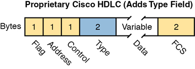
Figure 3-4 HDLC Framing
How Routers Use a WAN Data Link
Leased lines connect to routers, and routers focus on delivering packets to a destination host. However, routers physically connect to both LANs and WANs, with those LANs and WANs requiring that data be sent inside data-link frames. So, now that you know a little about HDLC, it helps to think about how routers use the HDLC protocol when sending data.
First, the TCP/IP network layer focuses on forwarding IP packets from the sending host to the destination host. The underlying LANs and WANs just act as a way to move the packets to the next router or end-user device. Figure 3-5 shows that network layer perspective.
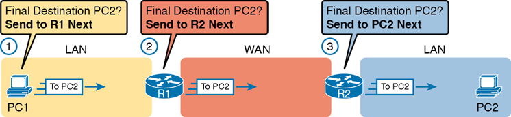
Figure 3-5 IP Routing Logic over LANs and WANs
Following the steps in the figure, for a packet sent by PC1 to PC2’s IP address:
PC1’s network layer (IP) logic tells it to send the packet to a nearby router (R1).
Router R1’s network layer logic tells it to forward (route) the packet out the leased line to Router R2 next.
Router R2’s network layer logic tells it to forward (route) the packet out the LAN link to PC2 next.
While Figure 3-5 shows the network layer logic, the PCs and routers must rely on the LANs and WANs in the figure to actually move the bits in the packet. Figure 3-6 shows the same figure, with the same packet, but this time showing some of the data-link layer logic used by the hosts and routers. Basically, three separate data-link layer steps encapsulate the packet, inside a data-link frame, over three hops through the internetwork: from PC1 to R1, from R1 to R2, and from R2 to PC2.

Figure 3-6 General Concept of Routers De-encapsulating and Re-encapsulating IP Packets
Following the steps in the figure, again for a packet sent by PC1 to PC2’s IP address:
To send the IP packet to Router R1 next, PC1 encapsulates the IP packet in an Ethernet frame that has the destination MAC address of R1.
Router R1 de-encapsulates (removes) the IP packet from the Ethernet frame, encapsulates the packet into an HDLC frame using an HDLC header and trailer, and forwards the HDLC frame to Router R2 next.
Router R2 de-encapsulates (removes) the IP packet from the HDLC frame, encapsulates the packet into an Ethernet frame that has the destination MAC address of PC2, and forwards the Ethernet frame to PC2.
In summary, a leased line with HDLC creates a WAN link between two routers so that they can forward packets for the devices on the attached LANs. The leased line itself provides the physical means to transmit the bits, in both directions. The HDLC frames provide the means to encapsulate the network layer packet correctly so that it crosses the link between routers.
Leased lines have many benefits that have led to their relatively long life in the WAN marketplace. These lines are simple for the customer, are widely available, are of high quality, and are private. However, they do have some negatives as well compared to newer WAN technologies, including a higher cost and typically longer lead times to get the service installed. Additionally, by today’s standards, leased-line LANs are slow, with faster speeds in the tens of megabits per second (Mbps). New faster WAN technology has been replacing leased lines for a long time, including the second WAN technology discussed in this book: Ethernet.
Ethernet as a WAN Technology
For the first several decades of the existence of Ethernet, Ethernet was only appropriate for LANs. The restrictions on cable lengths and devices might allow a LAN that stretched a kilometer or two, to support a campus LAN, but that was the limit.
As time passed, the IEEE improved Ethernet standards in ways that made Ethernet a reasonable WAN technology. For example, the 1000BASE-LX standard uses single-mode fiber cabling, with support for a 5-km cable length; the 1000BASE-ZX standard supports an even longer 70-km cable length. As time went by, and as the IEEE improved cabling distances for fiber Ethernet links, Ethernet became a reasonable WAN technology.
Today, many WAN service providers (SP) offer WAN services that take advantage of Ethernet. SPs offer a wide variety of these Ethernet WAN services, with many different names. But all of them use a similar model, with Ethernet used between the customer site and the SP’s network, as shown in Figure 3-7.
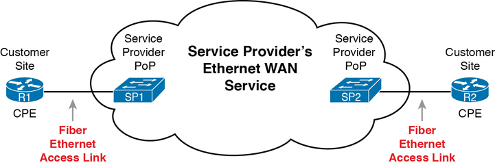
Figure 3-7 Fiber Ethernet Link to Connect a CPE Router to a Service Provider’s WAN
The model shown in Figure 3-7 has many of the same ideas of how a telco creates a leased line, as shown earlier in Figure 3-3, but now with Ethernet links and devices. The customer connects to an Ethernet link using a router interface. The (fiber) Ethernet link leaves the customer building and connects to some nearby SP location called a point of presence (PoP). Instead of a telco switch as shown in Figure 3-3, the SP uses an Ethernet switch. Inside the SP’s network, the SP uses any technology that it wants to create the specific Ethernet WAN services.
Ethernet WANs That Create a Layer 2 Service
Ethernet WAN services include a variety of specific services that vary in ways that change how routers use those services. However, for the purposes of CCNA, you just need to understand the most basic Ethernet WAN service, one that works much like an Ethernet crossover cable—just over a WAN. In other words:
Logically, behaves like a point-to-point connection between two routers
Physically, behaves as if a physical fiber Ethernet link existed between the two routers
Note
For perspective about the broad world of the service provider network shown in Figure 3-7, look for more information about the Cisco CCNA, CCNP Service Provider, and CCIE Service Provider certifications. See www.cisco.com/go/certifications for more details.
This book refers to this particular Ethernet WAN service with a couple of the common names:
Ethernet WAN: A generic name to differentiate it from an Ethernet LAN.
Ethernet Line Service (E-Line): A term from the Metro Ethernet Forum (MEF) for the kind of point-to-point Ethernet WAN service shown throughout this book.
Ethernet emulation: A term emphasizing that the link is not a literal Ethernet link from end to end.
Ethernet over MPLS (EoMPLS): A term that refers to Multiprotocol Label Switching (MPLS), a technology that can be used to create the Ethernet service for the customer.
So, if you can imagine two routers, with a single Ethernet link between the two routers, you understand what this particular EoMPLS service does, as shown in Figure 3-8. In this case, the two routers, R1 and R2, connect with an EoMPLS service instead of a serial link. The routers use Ethernet interfaces, and they can send data in both directions at the same time. Physically, each router actually connects to some SP PoP, as shown earlier in Figure 3-7, but logically, the two routers can send Ethernet frames to each other over the link.
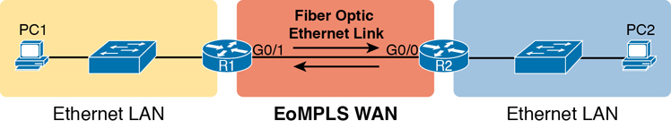
Figure 3-8 EoMPLS Acting Like a Simple Ethernet Link Between Two Routers
How Routers Route IP Packets Using Ethernet Emulation
WANs, by their very nature, give IP routers a way to forward IP packets from a LAN at one site, over the WAN, and to another LAN at another site. Routing over an EoMPLS WAN link still uses the WAN like a WAN, as a way to forward IP packets from one site to another. However, the WAN link happens to use the same Ethernet protocols as the Ethernet LAN links at each site.
The EoMPLS link uses Ethernet for both Layer 1 and Layer 2 functions. That means the link uses the same familiar Ethernet header and trailer, as shown in the middle of Figure 3-9. Note that the figure shows a small cloud over the Ethernet link as a way to tell us that the link is an Ethernet WAN link, rather than an Ethernet LAN link.
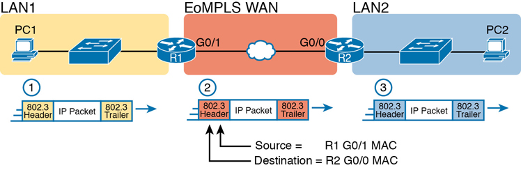
Figure 3-9 Routing over an EoMPLS Link
Note
The 802.3 headers/trailers in the figure are different at each stage! Make sure to notice the reasons in the step-by-step explanations that follow.
The figure shows the same three routing steps as shown with the serial link in the earlier Figure 3-6. In this case, all three routing steps use the same Ethernet (802.3) protocol. However, note that each frame’s data-link header and trailer are different. Each router discards the old data-link header/trailer and adds a new set, as described in these steps. Focus mainly on Step 2, because compared to the similar example shown in Figure 3-6, Steps 1 and 3 are unchanged:
To send the IP packet to Router R1 next, PC1 encapsulates the IP packet in an Ethernet frame that has the destination MAC address of R1.
Router R1 de-encapsulates (removes) the IP packet from the Ethernet frame and encapsulates the packet into a new Ethernet frame, with a new Ethernet header and trailer. The destination MAC address is R2’s G0/0 MAC address, and the source MAC address is R1’s G0/1 MAC address. R1 forwards this frame over the EoMPLS service to R2 next.
Router R2 de-encapsulates (removes) the IP packet from the Ethernet frame, encapsulates the packet into an Ethernet frame that has the destination MAC address of PC2, and forwards the Ethernet frame to PC2.
Throughout this book, the WAN links (serial and Ethernet) will connect routers as shown here, with the focus being on the LANs and IP routing. The rest of the chapter turns our attention to a closer look at IP routing.
IP Routing
Many protocol models have existed over the years, but today the TCP/IP model dominates. And at the network layer of TCP/IP, two options exist for the main protocol around which all other network layer functions revolve: IP version 4 (IPv4) and IP version 6 (IPv6). Both IPv4 and IPv6 define the same kinds of network layer functions, but with different details. This chapter introduces these network layer functions for IPv4.
Note
All references to IP in this chapter refer to the older and more established IPv4.
Internet Protocol (IP) focuses on the job of routing data, in the form of IP packets, from the source host to the destination host. IP does not concern itself with the physical transmission of data, instead relying on the lower TCP/IP layers to do the physical transmission of the data. Instead, IP concerns itself with the logical details, rather than physical details, of delivering data. In particular, the network layer specifies how packets travel end to end over a TCP/IP network, even when the packet crosses many different types of LAN and WAN links.
This next major section of the chapter examines IP routing in more depth. First, IP defines what it means to route an IP packet from sending host to destination host, while using successive data-link protocols. This section then examines how IP addressing rules help to make IP routing much more efficient by grouping addresses into subnets. This section closes by looking at the role of IP routing protocols, which give routers a means by which to learn routes to all the IP subnets in an internetwork.
Network Layer Routing (Forwarding) Logic
Routers and end-user computers (called hosts in a TCP/IP network) work together to perform IP routing. The host operating system (OS) has TCP/IP software, including the software that implements the network layer. Hosts use that software to choose where to send IP packets, often to a nearby router. Those routers make choices of where to send the IP packet next. Together, the hosts and routers deliver the IP packet to the correct destination, as shown in the example in Figure 3-10.
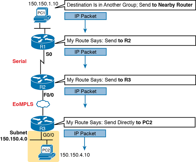
Figure 3-10 Routing Logic: PC1 Sending an IP Packet to PC2
The IP packet, created by PC1, goes from the top of the figure all the way to PC2 at the bottom of the figure. The next few pages discuss the network layer routing logic used by each device along the path.
Note
The term path selection is sometimes used to refer to the routing process shown in Figure 3-10. At other times, it refers to routing protocols, specifically how routing protocols select the best route among the competing routes to the same destination.
Host Forwarding Logic: Send the Packet to the Default Router
In this example, PC1 does some basic analysis and then chooses to send the IP packet to the router so that the router will forward the packet. PC1 analyzes the destination address and realizes that PC2’s address (150.150.4.10) is not on the same LAN as PC1. So PC1’s logic tells it to send the packet to a device whose job it is to know where to route data: a nearby router, on the same LAN, called PC1’s default router.
To send the IP packet to the default router, the sender sends a data-link frame across the medium to the nearby router; this frame includes the packet in the data portion of the frame. That frame uses data-link layer (Layer 2) addressing in the data-link header to ensure that the nearby router receives the frame.
Note
The default router is also referred to as the default gateway.
R1 and R2’s Logic: Routing Data Across the Network
All routers use the same general process to route the packet. Each router keeps an IP routing table. This table lists IP address groupings, called IP networks and IP subnets. When a router receives a packet, it compares the packet’s destination IP address to the entries in the routing table and makes a match. This matching entry also lists directions that tell the router where to forward the packet next.
In Figure 3-10, R1 would have matched the destination address (150.150.4.10) to a routing table entry, which in turn told R1 to send the packet to R2 next. Similarly, R2 would have matched a routing table entry that told R2 to send the packet, over an Ethernet WAN link, to R3 next.
The routing concept works a little like driving down the freeway when approaching a big interchange. You look up and see signs for nearby towns, telling you which exits to take to go to each town. Similarly, the router looks at the IP routing table (the equivalent of the road signs) and directs each packet over the correct next LAN or WAN link (the equivalent of a road).
R3’s Logic: Delivering Data to the End Destination
The final router in the path, R3, uses almost the same logic as R1 and R2, but with one minor difference. R3 needs to forward the packet directly to PC2, not to some other router. On the surface, that difference seems insignificant. In the next section, when you read about how the network layer uses LANs and WANs, the significance of the difference will become obvious.
How Network Layer Routing Uses LANs and WANs
While the network layer routing logic ignores the physical transmission details, the bits still have to be transmitted. To do that work, the network layer logic in a host or router must hand off the packet to the data-link layer protocols, which, in turn, ask the physical layer to actually send the data. The data-link layer adds the appropriate header and trailer to the packet, creating a frame, before sending the frames over each physical network.
The routing process forwards the network layer packet from end to end through the network, while each data-link frame only takes a smaller part of the trip. Each successive data-link layer frame moves the packet to the next device that thinks about network layer logic. In short, the network layer thinks about the bigger view of the goal, like “Send this packet to the specified next router or host…,” while the data-link layer thinks about the specifics, like “Encapsulate the packet in a data-link frame and transmit it.” The following list summarizes the major steps in a router’s internal network layer routing for each packet beginning with the a frame arriving in a router interface:
Step 1. Use the data-link Frame Check Sequence (FCS) field to ensure that the frame had no errors; if errors occurred, discard the frame.
Step 2. Assuming that the frame was not discarded at Step 1, discard the old data-link header and trailer, leaving the IP packet.
Step 3. Compare the IP packet’s destination IP address to the routing table, and find the route that best matches the destination address. This route identifies the outgoing interface of the router and possibly the next-hop router IP address.
Step 4. Encapsulate the IP packet inside a new data-link header and trailer, appropriate for the outgoing interface, and forward the frame.
Figure 3-11 works through a repeat example of a packet sent by PC1 to PC2, followed by a detailed analysis of each device’s routing logic. Each explanation includes the details about how PC1 and each of the three routers builds the appropriate new data-link headers.
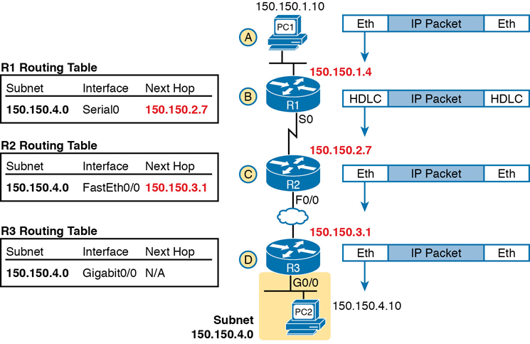
Figure 3-11 Network Layer and Data-Link Layer Encapsulation
The following list explains the forwarding logic at each router, focusing on how the routing integrates with the data link.
Step A. PC1 sends the packet to its default router. PC1’s network layer logic builds the IP packet, with a destination address of PC2’s IP address (150.150.4.10). The network layer also performs the analysis to decide that 150.150.4.10 is not in the local IP subnet, so PC1 needs to send the packet to R1 (PC1’s default router). PC1 places the IP packet into an Ethernet data-link frame, with a destination Ethernet address of R1’s Ethernet address. PC1 sends the frame on to the Ethernet.
Step B. R1 processes the incoming frame and forwards the packet to R2. Because the incoming Ethernet frame has a destination MAC of R1’s Ethernet MAC, R1 decides to process the frame. R1 checks the frame’s FCS for errors, and if none, R1 discards the Ethernet header and trailer. Next, R1 compares the packet’s destination address (150.150.4.10) to its routing table and finds the entry for subnet 150.150.4.0. Because the destination address of 150.150.4.10 is in that subnet, R1 forwards the packet out the interface listed in that matching route (Serial0) to next-hop Router R2 (150.150.2.7). R1 must first encapsulate the IP packet into an HDLC frame.
Step C. R2 processes the incoming frame and forwards the packet to R3. R2 repeats the same general process as R1 when R2 receives the HDLC frame. R2 checks the FCS field and finds that no errors occurred and then discards the HDLC header and trailer. Next, R2 compares the packet’s destination address (150.150.4.10) to its routing table and finds the entry for subnet 150.150.4.0, a route that directs R2 to send the packet out interface Fast Ethernet 0/0 to next-hop router 150.150.3.1 (R3). But first, R2 must encapsulate the packet in an Ethernet header. That header uses R2’s MAC address and R3’s MAC address on the Ethernet WAN link as the source and destination MAC address, respectively.
Step D. R3 processes the incoming frame and forwards the packet to PC2. Like R1 and R2, R3 checks the FCS, discards the old data-link header and trailer, and matches its own route for subnet 150.150.4.0. R3’s routing table entry for 150.150.4.0 shows that the outgoing interface is R3’s Ethernet interface, but there is no next-hop router because R3 is connected directly to subnet 150.150.4.0. All R3 has to do is encapsulate the packet inside a new Ethernet header and trailer, but with a destination Ethernet address of PC2’s MAC address.
Because the routers build new data-link headers and trailers, and because the new headers contain data-link addresses, the PCs and routers must have some way to decide what data-link addresses to use. An example of how the router determines which data-link address to use is the IP Address Resolution Protocol (ARP). ARP dynamically learns the data-link address of an IP host connected to a LAN. For example, at the last step, at the bottom of Figure 3-11, Router R3 would use ARP once to learn PC2’s MAC address before sending any packets to PC2.
How IP Addressing Helps IP Routing
IP defines network layer addresses that identify any host or router interface that connects to a TCP/IP network. The idea basically works like a postal address: Any interface that expects to receive IP packets needs an IP address, just like you need a postal address before receiving mail from the postal service. This next short topic introduces the idea of IP networks and subnets, which are the groups of addresses defined by IP.
Note
IP defines the word network to mean a very specific concept. To avoid confusion when writing about IP addressing, this book (and others) often avoids using the term network for other uses. In particular, this book uses the term internetwork to refer more generally to a network made up of routers, switches, cables, and other equipment.
Rules for Groups of IP Addresses (Networks and Subnets)
TCP/IP groups IP addresses together so that IP addresses used on the same physical network are part of the same group. IP calls these address groups an IP network or an IP subnet. Using that same postal service analogy, each IP network and IP subnet works like a postal code (or in the United States, a ZIP code). All nearby postal addresses are in the same postal code (ZIP code), while all nearby IP addresses must be in the same IP network or IP subnet.
IP defines specific rules about which IP address should be in the same IP network or IP subnet. Numerically, the addresses in the same group have the same value in the first part of the addresses. For example, Figures 3-10 and 3-11 could have used the following conventions:
Hosts on the top Ethernet: Addresses start with 150.150.1
Hosts on the R1–R2 serial link: Addresses start with 150.150.2
Hosts on the R2–R3 EoMPLS link: Addresses start with 150.150.3
Hosts on the bottom Ethernet: Addresses start with 150.150.4
From the perspective of IP routing, the grouping of IP addresses means that the routing table can be much smaller. A router can list one routing table entry for each IP network or subnet, instead of one entry for every single IP address.
While the list shows just one example of how IP addresses may be grouped, the rules for how to group addresses using subnets will require some work to master the concepts and math. Part III of this book details IP addressing and subnetting, and you can find other subnetting video and practice products listed in the Introduction to the book. However, the brief version of two of the foundational rules of subnetting can be summarized as follows:
Two IP addresses, not separated from each other by a router, must be in the same group (subnet).
Two IP addresses, separated from each other by at least one router, must be in different groups (subnets).
It’s similar to the USPS ZIP code system and how it requires local governments to assign addresses to new buildings. It would be ridiculous to have two houses next door to each other, whose addresses had different postal/ZIP codes. Similarly, it would be silly to have people who live on opposite sides of the country to have addresses with the same postal/ZIP code.
The IP Header
The routing process also makes use of the IPv4 header, as shown in Figure 3-12. The header lists a 32-bit source IP address, as well as a 32-bit destination IP address. The header, of course, has other fields, a few of which matter for other discussions in this book. The book will refer to this figure as needed, but otherwise, be aware of the 20-byte IP header and the existence of the source and destination IP address fields. Note that in the examples so far in this chapter, while routers remove and add data-link headers each time it routes a packet, the IP header remains, with the IP addresses unchanged by the IP routing process.
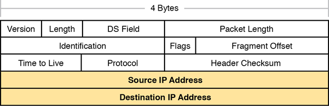
Figure 3-12 IPv4 Header, Organized as 4 Bytes Wide for a Total of 20 Bytes
How IP Routing Protocols Help IP Routing
For routing logic to work on both hosts and routers, each host and router needs to know something about the TCP/IP internetwork. Hosts need to know the IP address of their default router so that hosts can send packets to remote destinations. Routers, however, need to know routes so they forward packets to each and every reachable IP network and IP subnet.
The best method for routers to know all the useful routes is to configure the routers to use the same IP routing protocol. Alternately, a network engineer could configure (type) all the required routes, on every router. However, if you enable the same routing protocol on all the routers in a TCP/IP internetwork, with the correct settings, the routers will send routing protocol messages to each other. As a result, all the routers will learn routes for all the IP networks and subnets in the TCP/IP internetwork.
IP supports a small number of different IP routing protocols. All use some similar ideas and processes to learn IP routes, but different routing protocols do have some internal differences; otherwise, you would not need more than one routing protocol. However, many routing protocols use the same general steps for learning routes:
Step 1. Each router, independent of the routing protocol, adds a route to its routing table for each subnet directly connected to the router.
Step 2. Each router’s routing protocol tells its neighbors about the routes in its routing table, including the directly connected routes and routes learned from other routers.
Step 3. After learning a new route from a neighbor, the router’s routing protocol adds a route to its IP routing table, with the next-hop router of that route typically being the neighbor from which the route was learned.
Also, note that at the final step, routers may have to choose between multiple routes to reach a single subnet. When that happens, routers place the best currently available route to reach a subnet (based on a measurement called a metric) into the routing table.
Figure 3-13 shows an example of how a routing protocol works, using the same diagram as in Figures 3-10 and 3-11. In this case, IP subnet 150.150.4.0, which consists of all addresses that begin with 150.150.4.0, sits on the Ethernet at the bottom of the figure. The figure shows the advertisement of routes for subnet 150.150.4.0 from bottom to top, as described in detail following the figure.


Figure 3-13 Example of How Routing Protocols Advertise About Networks and Subnets
Follow items A through F shown in the figure to see how each router learns its route to 150.150.4.0.
Step A. Subnet 150.150.4.0 exists as a subnet at the bottom of the figure, connected to Router R3.
Step B. R3 adds a connected route for 150.150.4.0 to its IP routing table; this happens without help from the routing protocol.
Step C. R3 sends a routing protocol message, called a routing update, to R2, causing R2 to learn about subnet 150.150.4.0.
Step D. R2 adds a route for subnet 150.150.4.0 to its routing table.
Step E. R2 sends a similar routing update to R1, causing R1 to learn about subnet 150.150.4.0.
Step F. R1 adds a route for subnet 150.150.4.0 to its routing table. The route lists R1’s own Serial0 as the outgoing interface and R2 as the next-hop router IP address (150.150.2.7).
Other Network Layer Features
The TCP/IP network layer defines many functions beyond IP. Sure, IP plays a huge role in networking today, defining IP addressing and IP routing. However, other protocols and standards, defined in other Requests For Comments (RFC), play an important role for network layer functions as well. For example, routing protocols like Open Shortest Path First (OSPF) exist as separate protocols, defined in separate RFCs.
This last short section of the chapter introduces three other network layer features that should be helpful to you when reading through the rest of this book. These last three topics just help fill in a few holes, helping to give you some perspective and helping you make sense of later discussions as well. The three topics are
Domain Name System (DNS)
Address Resolution Protocol (ARP)
Ping
Using Names and the Domain Name System
Can you imagine a world in which every time you used an application, you had to refer to it by IP address? Instead of using easy names like google.com or facebook.com, you would have to remember and type IP addresses, like 64.233.177.100. (At press time, 64.233.177.100 was an address used by Google, and you could reach Google’s website by typing that address in a browser.) Certainly, asking users to remember IP addresses would not be user friendly and could drive some people away from using computers at all.
Thankfully, TCP/IP defines a way to use hostnames to identify other computers. The user either never thinks about the other computer or refers to the other computer by name. Then, protocols dynamically discover all the necessary information to allow communications based on that name.
For example, when you open a web browser and type in the hostname www.google.com, your computer does not send an IP packet with destination IP address www.google.com; it sends an IP packet to an IP address used by the web server for Google. TCP/IP needs a way to let a computer find the IP address used by the listed hostname, and that method uses the Domain Name System (DNS).
Enterprises use the DNS process to resolve names into the matching IP address, as shown in the example in Figure 3-14. In this case, PC11, on the left, needs to connect to a server named Server1. At some point, the user either types in the name Server1 or some application on PC11 refers to that server by name. At Step 1, PC11 sends a DNS message—a DNS query—to the DNS server. At Step 2, the DNS server sends back a DNS reply that lists Server1’s IP address. At Step 3, PC11 can now send an IP packet to destination address 10.1.2.3, the address used by Server1.

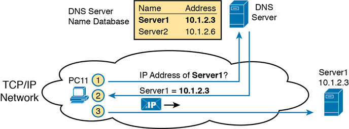
Figure 3-14 Basic DNS Name Resolution Request
Note that the example in Figure 3-14 shows a cloud for the TCP/IP network because the details of the network, including routers, do not matter to the name resolution process. Routers treat the DNS messages just like any other IP packet, routing them based on the destination IP address. For example, at Step 1 in the figure, the DNS query will list the DNS server’s IP address as the destination address, which any routers will use to forward the packet.
Finally, DNS defines much more than just a few messages. DNS defines protocols, as well as standards for the text names used throughout the world, and a worldwide set of distributed DNS servers. The domain names that people use every day when web browsing, which look like www.example.com, follow the DNS naming standards. Also, no single DNS server knows all the names and matching IP addresses, but the information is distributed across many DNS servers. So, the DNS servers of the world work together, forwarding queries to each other, until the server that knows the answer supplies the desired IP address information.
The Address Resolution Protocol
As discussed in depth throughout this chapter, IP routing logic requires that hosts and routers encapsulate IP packets inside data-link layer frames. For Ethernet interfaces, how does a router know what MAC address to use for the destination? It uses ARP.
On Ethernet LANs, whenever a host or router needs to encapsulate an IP packet in a new Ethernet frame, the host or router knows all the important facts to build that header—except for the destination MAC address. The host knows the IP address of the next device, either another host IP address or the default router IP address. A router knows the IP route used for forwarding the IP packet, which lists the next router’s IP address. However, the hosts and routers do not know those neighboring devices’ MAC addresses beforehand.
TCP/IP defines the Address Resolution Protocol (ARP) as the method by which any host or router on a LAN can dynamically learn the MAC address of another IP host or router on the same LAN. ARP defines a protocol that includes the ARP Request, which is a message that makes the simple request “if this is your IP address, please reply with your MAC address.” ARP also defines the ARP Reply message, which indeed lists both the original IP address and the matching MAC address.
Figure 3-15 shows an example that uses the same router and host from the bottom part of the earlier Figure 3-13. The figure shows the ARP Request sent by router R3, on the left of the figure, as a LAN broadcast. All devices on the LAN will then process the received frame. On the right, at Step 2, host PC2 sends back an ARP Reply, identifying PC2’s MAC address. The text beside each message shows the contents inside the ARP message itself, which lets PC2 learn R3’s IP address and matching MAC address, and R3 learn PC2’s IP address and matching MAC address.
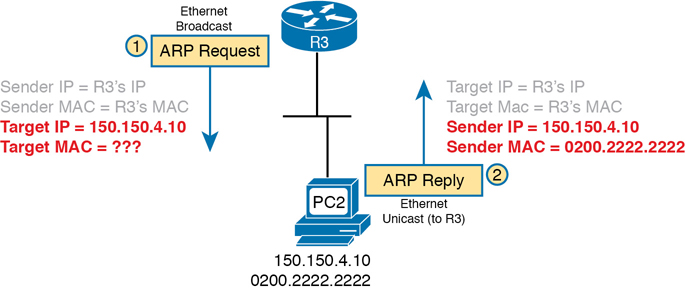
Figure 3-15 Sample ARP Process
Note that hosts and routers remember the ARP results, keeping the information in their ARP cache or ARP table. A host or router only needs to use ARP occasionally, to build the ARP cache the first time. Each time a host or router needs to send a packet encapsulated in an Ethernet frame, it first checks its ARP cache for the correct IP address and matching MAC address. Hosts and routers will let ARP cache entries time out to clean up the table, so occasional ARP Requests can be seen.
Note
You can see the contents of the ARP cache on most PC operating systems by using the arp -a command from a command prompt.
ICMP Echo and the ping Command
After you have implemented a TCP/IP internetwork, you need a way to test basic IP connectivity without relying on any applications to be working. The primary tool for testing basic network connectivity is the ping command.
Ping (Packet Internet Groper) uses the Internet Control Message Protocol (ICMP), sending a message called an ICMP echo request to another IP address. The computer with that IP address should reply with an ICMP echo reply. If that works, you successfully have tested the IP network. In other words, you know that the network can deliver a packet from one host to the other and back. ICMP does not rely on any application, so it really just tests basic IP connectivity—Layers 1, 2, and 3 of the OSI model. Figure 3-16 outlines the basic process.
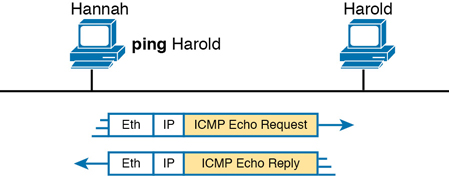
Figure 3-16 Sample Network, ping Command
Note that while the ping command uses ICMP, ICMP does much more. ICMP defines many messages that devices can use to help manage and control the IP network.
Chapter Review
The “Your Study Plan” element, just before Chapter 1, discusses how you should study and practice the content and skills for each chapter before moving on to the next chapter. That element introduces the tools used here at the end of each chapter. If you haven’t already done so, take a few minutes to read that section. Then come back here and do the useful work of reviewing the chapter to help lock into memory what you just read.
Review this chapter’s material using either the tools in the book or interactive tools for the same material found on the book’s companion website. Table 3-4 outlines the key review elements and where you can find them. To better track your study progress, record when you completed these activities in the second column.
Table 3-4 Chapter Review Tracking
Review Element |
Review Date(s) |
Resource Used |
|---|---|---|
Review key topics |
|
Book, website |
Review key terms |
|
Book, website |
Answer DIKTA questions |
|
Book, PTP |
Review memory tables |
|
Book, website |
Review All the Key Topics
Table 3-5 Key Topics for Chapter 3
Key Topic Element |
Description |
Page Number |
|---|---|---|
Ethernet over MPLS—physical connections |
66 |
|
List |
Four-step process of how routers route (forward) packets |
70 |
IP Routing and Encapsulation |
71 |
|
List |
Two statements about how IP expects IP addresses to be grouped into networks or subnets |
73 |
List |
Three-step process of how routing protocols learn routes |
74 |
IP Routing Protocol Basic Process |
75 |
|
Example that shows the purpose and process of DNS name resolution |
76 |
|
Example of the purpose and process of ARP |
78 |
Key Terms You Should Know
Ethernet Line Service (E-Line)