Chapter 7
WAN Concepts
Objectives
Upon completion of this chapter, you will be able to answer the following questions:
What is the purpose of a WAN?
How do WANs operate?
What are traditional WAN connectivity options?
What are modern WAN connectivity options?
What are internet-based connectivity options?
Key Terms
This chapter uses the following key terms. You can find the definitions in the Glossary.
enterprise campus network page 272
point-to-point topology page 274
hub-and-spoke topology page 274
fully meshed topology page 274
partially meshed topology page 274
single-homed topology page 275
single point of failure page 275
service level agreement (SLA) page 278
single-carrier connection page 278
dual-carrier connection page 278
digital subscriber line (DSL) page 280
virtual private network (VPN) page 282
Telecommunications Industry Association (TIA) page 283
Electronic Industries Alliance (EIA) page 283
International Organization for Standardization (ISO) page 283
Institute of Electrical and Electronics Engineers (IEEE) page 283
Synchronous Digital Hierarchy (SDH) page 284
Synchronous Optical Networking (SONET) page 284
Dense wavelength-division multiplexing (DWDM) page 284
Metro Ethernet (MetroE) page 285
Multiprotocol Label Switching (MPLS) page 285
Point-to-Point Protocol (PPP) page 285
High-Level Data Link Control (HDLC) page 285
Asynchronous Transfer Mode (ATM) page 285
data terminal equipment (DTE) page 286
data communications equipment (DCE) page 286
customer premises equipment (CPE) page 286
point of presence (POP) page 286
local loop (or last mile) page 286
circuit-switched communication page 290
public switched telephone network (PSTN) page 290
Integrated Services Digital Network (ISDN) page 290
packet-switched communication page 290
light-emitting diode (LED) page 291
non-broadcast multiaccess (NBMA) page 295
permanent virtual circuit (PVC) page 295
data-link connection identifier (DLCI) page 296
Ethernet over MPLS (EoMPLS) page 299
Virtual Private LAN Service (VPLS) page 299
asymmetric DSL (ADSL) page 303
DSL access multiplexer (DSLAM) page 303
PPP over Ethernet (PPPoE) page 304
Data over Cable Service Interface Specification (DOCSIS) page 305
hybrid fiber-coaxial (HFC) page 305
cable modem termination system (CMTS) page 305
fiber-to-the-home (FTTH) page 306
fiber-to-the-building (FTTB) page 306
fiber-to-the-node/neighborhood (FTTN) page 306
Long-Term Evolution (LTE) page 307
Worldwide Interoperability for Microwave Access (WiMAX) page 307
Introduction (7.0)
As you know, local-area networks are called LANs. The name implies that a LAN is local to you and your small home or office business. But what if your network is for a larger business or perhaps even a global enterprise? You cannot operate a large business with multiple sites without a wide-area network, which is called a WAN. This chapter explains what WANs are and how they connect to the internet and also back to your LAN. Understanding the purpose and functions of WANs is foundational to your understanding of modern networks. Let’s jump in!
Purpose of WANs (7.1)
In this section, you will learn about WAN access technologies available to small to medium-sized business networks.
LANs and WANs (7.1.1)
Whether at work or at home, we all use local-area networks (LANs). However, LANs are limited to a small geographic area. A wide-area network (WAN) is required to connect beyond the boundaries of a LAN. A WAN is a telecommunications network that spans a relatively large geographic area and operates beyond the geographic scope of a LAN.
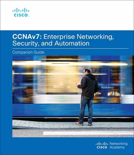
In Figure 7-1, WAN services are required to interconnect an enterprise campus network to remote LANs at branch sites, telecommuter sites, and remote users.
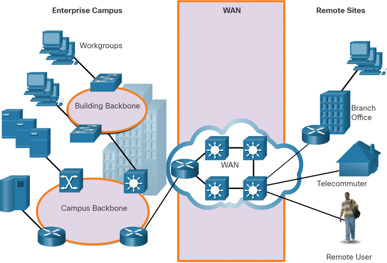
Figure 7-1 Examples of Different Types of WAN Services
Table 7-1 highlights the differences between LANs and WANs.
Table 7-1 Differences Between LANs and WANs
Local-Area Networks (LANs) |
Wide-Area Networks (WANs) |
LANs provide networking services within a small geographic area (such as a home network, office network, building network, or campus network). |
WANs provide networking services over large geographic areas (such as in and between cities, countries, and continents). |
LANs are used to interconnect local computers, peripherals, and other devices. |
WANs are used to interconnect remote users, networks, and sites. |
A LAN is owned and managed by an organization or a home user. |
WANs are owned and managed by internet service, telephone, cable, and satellite providers. |
Other than the network infrastructure costs, there is no fee to use a LAN. |
WAN services are provided for a fee. |
LANs provide high-bandwidth speeds using wired Ethernet and Wi-Fi services. |
WANs providers offer low- to high-bandwidth speeds over long distances using complex physical networks. |
Private and Public WANs (7.1.2)
WANs may be built by a variety of different types of organizations, including the following:
An organization that wants to connect users in different locations
An ISP that wants to connect customers to the internet
An ISP or telecommunications provider that wants to interconnect ISPs
A private WAN connection is dedicated to a single customer. It provides for the following:
Guaranteed service level
Consistent bandwidth
Security
A public WAN connection is typically provided by an ISP or a telecommunications service provider using the internet. With a public WAN, the service levels and bandwidth may vary, and the shared connections do not guarantee security.
WAN Topologies (7.1.3)
A physical topology describes the physical network infrastructure used by data when it is traveling from a source to a destination. The physical WAN topology used in WANs is complex and, for the most part, unknown to users. Consider a user in New York establishing a video conference call with a user in Tokyo, Japan. Other than the user’s internet connection in New York, it would not be feasible to identify all the actual physical connections needed to support the video call.
A WAN topology is described using a logical topology, which includes the virtual connection between the source and destination. For example, a video conference call between a user in New York and a user in Japan would be a logical point-to-point connection.
WANs are implemented using the following logical topology designs:
Note
Large networks usually deploy a combination of these topologies.
Point-to-Point Topology
A point-to-point topology, as shown in Figure 7-2, uses a point-to-point circuit between two endpoints.

Figure 7-2 Point-to-Point Topology
Point-to-point links often involve dedicated, leased-line connections from the corporate edge point to the provider networks. A point-to-point connection involves a Layer 2 transport service through the service provider network. Packets sent from one site are delivered to the other site and vice versa. A point-to-point connection is transparent to the customer network. It seems as if there is a direct physical link between two endpoints.
Point-to-point topology can become expensive if many point-to-point connections are required.
Hub-and-Spoke Topology
A hub-and-spoke topology enables a single interface on the hub router to be shared by all spoke circuits. Spoke routers can be interconnected through the hub router using virtual circuits and routed subinterfaces. Figure 7-3 displays a sample hub-and-spoke topology consisting of three spoke routers connecting to a hub router across a WAN cloud.

Figure 7-3 Hub-and-Spoke Topology
A hub-and-spoke topology is a single-homed topology. There is only one hub router, and all communication must go through it. Therefore, spoke routers can only communicate with each other through the hub router. Consequently, the hub router represents a single point of failure. If it fails, inter-spoke communication also fails.
Dual-homed Topology
A dual-homed topology provides redundancy. Figure 7-4 shows such a topology, with two hub routers dual-homed and redundantly attached to three spoke routers across a WAN cloud.
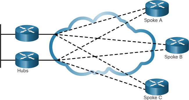
Figure 7-4 Dual-Homed Topology
The advantage of dual-homed topologies is that they offer enhanced network redundancy, load balancing, distributed computing and processing, and the ability to implement backup service provider connections.
The disadvantage is that they are more expensive to implement than single-homed topologies. This is because they require additional networking hardware, such as additional routers and switches. Dual-homed topologies are also more difficult to implement because they require additional, and more complex, configurations.
Fully Meshed Topology
A fully meshed topology uses multiple virtual circuits to connect all sites, as shown in Figure 7-5.
This is the most fault-tolerant topology of the five shown in this chapter. For instance, if site B lost connectivity to site A, it could send the data through either site C or site D.
Figure 7-5 Fully Meshed Topology
Partially Meshed Topology
A partially meshed topology connects many but not all sites. For example, in Figure 7-6, sites A, B, and C are fully meshed, but site D must connect to site A to reach sites B and C.

Figure 7-6 Partially Meshed Topology
Carrier Connections (7.1.4)
An important aspect of WAN design is how an organization connects to the internet. An organization usually signs a service level agreement (SLA) with a service provider. The SLA outlines the expected services related to the reliability and availability of the connection. The service provider may or may not be the actual carrier. A carrier owns and maintains the physical connection and equipment between the provider and the customer. Typically, an organization chooses either a single-carrier or dual-carrier WAN connection.
Single-Carrier WAN Connection
With a single-carrier connection, an organization connects to only one service provider, as shown in Figure 7-7. An SLA is negotiated between the organization and the service provider. The disadvantage of this design is that the carrier connection and service provider are both single points of failure. Connectivity to the internet would be lost if the carrier link failed or if the provider router failed.

Figure 7-7 Example of a Single-Carrier WAN Connection
Dual-Carrier WAN Connection
A dual-carrier connection provides redundancy and increases network availability, as shown in Figure 7-8. The organization negotiates separate SLAs with two different service providers. The organization should ensure that the two providers each use a different carrier. Although a dual-carrier connection is more expensive to implement than a single-carrier connection, the second connection can be used for redundancy (that is, as a backup link). It can also be used to improve network performance and load balance internet traffic.
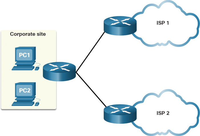
Figure 7-8 Example of a Dual-Carrier WAN Connection
Evolving Networks (7.1.5)
A company’s network requirements can change dramatically as the company grows over time. Distributing employees saves costs in many ways, but it puts increased demands on the network. A network must meet the day-to-day operational needs of the business, and it also must be able to adapt and grow as the company changes. Network designers and administrators meet these challenges by carefully choosing network technologies, protocols, and service providers. They must also optimize their networks by using a variety of network design techniques and architectures.
To illustrate differences between networks of various sizes, in this chapter we use a fictitious company called SPAN Engineering and watch as it grows from a small local business into a global enterprise. SPAN Engineering, an environmental consulting firm, has developed a special process for converting household waste into electricity and is developing a small pilot project for a municipal government in its local area.
Small Network
SPAN Engineering initially consisted of 15 employees working in a small office, as shown in Figure 7-9.

Figure 7-9 Example of a Small Network
They used a single LAN connected to a wireless router for sharing data and peripherals. The connection to the internet was through a common broadband service called digital subscriber line (DSL), supplied by the local telephone service provider. To support the company IT requirements, SPAN contracted services from the DSL provider.
Campus Network
Within a few years, SPAN Engineering grew to require several floors of a building, as shown in Figure 7-10.
The company now required a campus-area network (CAN). A CAN interconnects several LANs within a limited geographic area. Multiple LANs are required to segment the various departments that are connecting to multiple switches in a campus network environment.
The network includes dedicated servers for email, data transfer, file storage, and web-based productivity tools and applications. A firewall secures internet access to corporate users. The business now requires in-house IT staff to support and maintain the network.

Figure 7-10 Example of a Campus Network
Branch Network
A few years later, SPAN Engineering expanded and added a branch site in the city and remote and regional sites in other cities, as shown in Figure 7-11.
The company now required a metropolitan-area network (MAN) to interconnect sites within the city. A MAN is larger than a LAN but smaller than a WAN.
To connect to the central office, branch offices in nearby cities used private dedicated lines through their local service provider. Offices in other cities and countries require the services of a WAN or may use internet services to connect distant locations. However, the internet introduces security and privacy issues that the IT team must address.
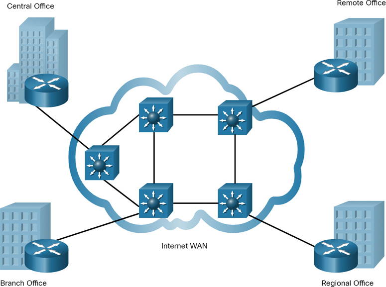
Figure 7-11 Example of a Branch Network
Distributed Network
SPAN Engineering has now been in business for 20 years and has grown to having thousands of employees distributed in offices worldwide, as shown in Figure 7-12.
To reduce network costs, SPAN encouraged teleworking and virtual teams using web-based applications, including web conferencing, e-learning, and online collaboration tools to increase productivity and reduce costs. Site-to-site and remote-access virtual private networks (VPNs) enable the company to use the internet to connect easily and securely with employees and facilities around the world.
Check Your Understanding—Purpose of WANs (7.1.6)

Refer to the online course to complete this activity.

Figure 7-12 Example of a Distributed Network
WAN Operations (7.2)
Now that you understand how critical WANs are to large networks, this section discusses how they work. The concept of a WAN has been around for many years. Consider that the telegraph system was the first large-scale WAN, followed by radio, telephone system, television, and now data networks. Many of the technologies and standards developed for these WANs were used as the basis for network WANs.
WAN Standards (7.2.1)
Modern WAN standards are defined and managed by a number of recognized authorities, including the following:
WANs in the OSI Model (7.2.2)
Most WAN standards focus on the physical layer (OSI Layer 1) and the data link layer (OSI Layer 2), as shown in Figure 7-13.

Figure 7-13 WAN Services and the OSI Model
Layer 1 Protocols
Layer 1 protocols describe the electrical, mechanical, and operational components needed to transmit bits over a WAN. For example, service providers commonly use high-bandwidth optical fiber media to span long distances (that is, long haul) using the following Layer 1 optical fiber protocol standards:
SDH and SONET essentially provide the same services, and their transmission capacity can be increased by using DWDM technology.
Layer 2 Protocols
Layer 2 protocols define how data will be encapsulated into a frame. Several Layer 2 protocols have evolved over the years, including the following:
Broadband (such as DSL and cable)
Wireless
Point-to-Point Protocol (PPP) (not commonly used)
High-Level Data Link Control (HDLC) (not commonly used)
Frame Relay (legacy)
Asynchronous Transfer Mode (ATM) (legacy)
Common WAN Terminology (7.2.3)
The WAN physical layer describes the physical connections between the company network and the service provider network.
Specific terms are used to describe WAN connections between the subscriber that is, the company/client) and the WAN service provider, as shown in Figure 7-14.
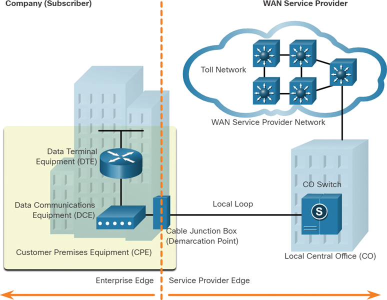
Figure 7-14 Topology Example with Common WAN Terminology
Table 7-2 explains the terms shown in Figure 7-14, as well as some additional WAN-related terms.
Table 7-2 WAN Terminology
WAN Term |
Description |
|
|
|
|
|
|
|
|
|
|
|
|
|
|
|
|
|
|
|
WAN Devices (7.2.4)
Many types of devices are specific to WAN environments. However, the end-to-end data path over a WAN is usually from the source DTE to the DCE, then to the WAN cloud, then to the DCE, and finally to the destination DTE, as shown in Figure 7-15.
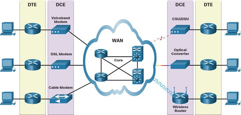
Figure 7-15 Examples of DTE and DCE in WAN Services
Table 7-3 describes the WAN devices shown in Figure 7-15.
Table 7-3 WAN Device Descriptions
WAN Device |
Description |
|
|
DSL modem and cable modem |
|
|
|
|
|
Wireless router or access point |
|
WAN core devices |
|
Note
The list in Table 7-3 is not exhaustive, and other devices may be required, depending on the WAN access technology chosen.
Serial Communication (7.2.5)
Almost all network communications occur using serial communication delivery. Serial communication transmits bits sequentially over a single channel. In contrast, parallel communications simultaneously transmit several bits using multiple wires.
Figure 7-16 demonstrates the difference between serial and parallel communications.

Figure 7-16 Serial and Parallel Communications
Although a parallel connection theoretically transfers data eight times faster than a serial connection, it is prone to synchronization problems. As the cable length increases, the synchronization timing between multiple channels becomes more sensitive to distance. For this reason, parallel communication is limited to very short distances only; for example, copper media is limited to less than 8 meters (that is, 26 feet).
Parallel communication is not a viable WAN communication method because of its length restriction. It is, however, a viable solution in data centers, where distances between servers and switches are relatively short. For instance, the Cisco Nexus switches in data centers support parallel optics solutions to transfer more data signals and achieve higher speeds (such as 40 Gbps and 100 Gbps).
Circuit-Switched Communication (7.2.6)
Network communication can be implemented using circuit-switched communication. A circuit-switched network establishes a dedicated circuit (or channel) between endpoints before the users can communicate. Specifically, circuit switching dynamically establishes a dedicated virtual connection through the service provider network before voice or data communication can start, as shown in Figure 7-17.

Figure 7-17 Example of Circuit-Switched Communications
For example, when a user makes a telephone call using a landline, the number called is used by the provider equipment to create a dedicated circuit from the caller to the called party.
Note
A landline is a telephone situated in a fixed location that is connected to the provider using copper or fiber-optic media.
During transmission over a circuit-switched network, all communication uses the same path. The entire fixed capacity allocated to the circuit is available for the duration of the connection, regardless of whether there is information to transmit. This can lead to inefficiencies in circuit usage. For this reason, circuit switching is generally not suited for data communication.
The two most common types of circuit-switched WAN technologies are the public switched telephone network (PSTN) and the legacy Integrated Services Digital Network (ISDN).
Packet-Switched Communications (7.2.7)
Network communication is most commonly implemented using packet-switched communication. In contrast to circuit switching, packet switching segments traffic data into packets that are routed over a shared network. Packet-switched networks do not require a circuit to be established, and they allow many pairs of nodes to communicate over the same channel, as shown in Figure 7-18.

Figure 7-18 Example of Packet-Switched Communications
Packet switching is much less expensive and more flexible than circuit switching. Although susceptible to delays (latency) and variability of delay (jitter), modern packet-switching technology allows satisfactory transport of voice and video communications on these networks.
Examples of packet-switched WAN technologies are Ethernet WAN (Metro Ethernet) and Multiprotocol Label Switching (MPLS), as well as the legacy technologies Frame Relay and Asynchronous Transfer Mode (ATM).
SDH, SONET, and DWDM (7.2.8)
Service provider networks use fiber-optic infrastructures to transport user data between destinations. Fiber-optic cable is far superior to copper cable for long-distance transmissions due to its much lower attenuation and interference.
There are two optical fiber OSI Layer 1 standards available to service providers:
SDH: Synchronous Digital Hierarchy (SDH) is a global standard for transporting data over fiber-optic cable.
SONET: Synchronous Optical Networking (SONET) is the North American standard that provides the same services as SDH.
These two standards are essentially the same, and they are therefore often listed as SONET/SDH.
SONET and SDH define how to transfer multiple data, voice, and video communications over optical fiber using lasers or light-emitting diodes (LEDs) over great distances. Both standards are used on the ring network topology, which contains the redundant fiber paths that allow traffic to flow in both directions.
Dense wavelength-division multiplexing (DWDM) is a newer technology that increases the data-carrying capacity of SDH and SONET by simultaneously sending multiple streams of data (multiplexing) using different wavelengths of light, as shown in Figure 7-19.

Figure 7-19 DWDM Multiplexing
DWDM has the following features:
It supports SONET and SDH standards.
It can multiplex more than 80 different channels of data (that is, wavelengths) onto a single fiber.
Each channel is capable of carrying a 10 Gbps multiplexed signal.
It assigns incoming optical signals to specific wavelengths of light (that is, frequencies).
Note
DWDM circuits are used in long-haul systems and modern submarine communications cable systems.
Check Your Understanding—WAN Operations (7.2.9)
Refer to the online course to complete this activity.
Traditional WAN Connectivity (7.3)
To understand the WANs of today, it helps to know where they started. This section discusses WAN connectivity options from the beginning.
Traditional WAN Connectivity Options (7.3.1)
When LANs appeared in the 1980s, organizations began to see the need to interconnect with other locations. To do so, they needed their networks to connect to the local loop of a service provider. This was accomplished by using dedicated lines or by using switched services from a service provider.
Figure 7-20 summarizes the traditional WAN connectivity options.
Note
There are several WAN access connection options that the enterprise edge can use to connect over the local loop to the provider. These WAN access options differ in technology, bandwidth, and cost. Each has distinct advantages and disadvantages. Familiarity with these technologies is an important part of network design.

Figure 7-20 Traditional WAN Connectivity Options
Common WAN Terminology (7.3.2)
When permanent dedicated connections were required, a point-to-point link using copper media was used to provide a preestablished WAN communications path from the customer premises to the provider network. Point-to-point lines could be leased from a service provider. These lines are called leased lines because the organization pays a monthly lease fee to a service provider to use the lines.
Leased lines have existed since the early 1950s. They are referred to by different names, such as leased circuits, serial links, serial lines, point-to-point links, and T1/E1 or T3/E3 lines.
Leased lines are available in different fixed capacities and are generally priced based on the bandwidth required and the distance between the two connected points.
There are two systems used to define the digital capacity of a copper media serial link:
T-carrier: Used in North America, T-carrier provides T1 links supporting bandwidth up to 1.544 Mbps and T3 links supporting bandwidth up to 43.7 Mbps.
E-carrier: Used in Europe, E-carrier provides E1 links supporting bandwidth up to 2.048 Mbps and E3 links supporting bandwidth up to 34.368 Mbps.
Note
The copper cable physical infrastructure has largely been replaced by optical fiber networks. Transmission rates in optical fiber networks are given in terms of Optical Carrier (OC) transmission rates, which define the digital transmitting capacity of a fiber-optic network.
Table 7-4 summarizes the advantages and disadvantages of leased lines.
Table 7-4 Advantages and Disadvantages of Leased Lines
Advantage |
Description |
Simplicity |
Point-to-point communication links require minimal expertise to install and maintain. |
Quality |
Point-to-point communication links usually offer high-quality service if they have adequate bandwidth. The dedicated capacity removes latency or jitter between the endpoints. |
Availability |
Constant availability is essential for some applications, such as e-commerce. Point-to-point communication links provide permanent, dedicated capacity, which is required for voice over IP (VoIP) or video over IP. |
Disadvantage |
Description |
Cost |
Point-to-point links are generally the most expensive type of WAN access. The cost of leased line solutions can become significant when they are used to connect many sites over increasing distances. In addition, each endpoint requires an interface on the router, which increases equipment costs. |
Limited flexibility |
WAN traffic is often variable, and leased lines have a fixed capacity, so that the bandwidth of the line seldom matches the need exactly. Any change to the leased line generally requires a site visit by ISP personnel to adjust capacity. |
Circuit-Switched Options (7.3.3)
Circuit-switched connections are provided by public switched telephone network (PSTN) carriers. The local loop connecting the CPE to the CO is copper media. There are two traditional circuit-switched options: the PSTN and ISDN.
Public Service Telephone Network (PSTN)
Dialup WAN access uses the PSTN as its WAN connection. Traditional local loops can transport binary computer data through the voice telephone network using a voiceband modem. The modem modulates the digital data into an analog signal at the source and demodulates the analog signal to digital data at the destination. The physical characteristics of the local loop and its connection to the PSTN limit the rate of the signal to less than 56 kbps.
Dialup access is considered a legacy WAN technology. However, it may still be a viable solution when no other WAN technology is available.
Integrated Services Digital Network (ISDN)
ISDN is a circuit-switching technology that enables the PSTN local loop to carry digital signals. It provided higher-capacity switched connections than dialup access. ISDN provides for data rates from 45 Kbps to 2.048 Mbps.
ISDN has declined greatly in popularity due to high-speed DSL and other broadband services. ISDN is considered a legacy technology, and most major providers have discontinued this service.
Packet-Switched Options (7.3.4)
Packet switching segments data into packets that are routed over a shared network. Circuit-switched networks require a dedicated circuit to be established. In contrast, packet-switching networks allow many pairs of nodes to communicate over the same channel.
There are two traditional (legacy) packet-switched connectivity options: Frame Relay and ATM.
Frame Relay
Frame Relay is a simple Layer 2 non-broadcast multiaccess (NBMA) WAN technology that is used to interconnect enterprise LANs. A single router interface can be used to connect to multiple sites using different permanent virtual circuits (PVCs). PVCs are used to carry both voice and data traffic between a source and destination, and they support data rates up to 4 Mbps, with some providers offering even higher rates.
Frame Relay creates PVCs that are uniquely identified by data-link connection identifiers (DLCIs). The PVCs and DLCIs ensure bidirectional communication from one DTE device to another.
Frame Relay networks have been largely replaced by faster Metro Ethernet and internet-based solutions.
Asynchronous Transfer Mode (ATM)
Asynchronous Transfer Mode (ATM) technology is capable of transferring voice, video, and data through private and public networks. It is built on a cell-based architecture rather than on a frame-based architecture. ATM cells are always a fixed length of 53 bytes. An ATM cell contains a 5-byte ATM header followed by 48 bytes of ATM payload. Small, fixed-length cells are well suited for carrying voice and video traffic because this traffic is intolerant of delay. Video and voice traffic do not have to wait for larger data packets to be transmitted.
The 53-byte ATM cell is less efficient than the bigger frames and packets of Frame Relay. Furthermore, the ATM cell has at least 5 bytes of overhead for each 48-byte payload. When a cell is carrying segmented network layer packets, the overhead is higher because the ATM switch must be able to reassemble the packets at the destination. A typical ATM line needs almost 20% greater bandwidth than Frame Relay to carry the same volume of network layer data.
ATM networks have been largely replaced by faster Metro Ethernet and internet-based solutions.
Check Your Understanding—Traditional WAN Connectivity (7.3.5)
Refer to the online course to complete this activity.
Modern WAN Connectivity (7.4)
This section discusses the various modern WAN services available.
Modern WANs (7.4.1)
Modern WANs have more connectivity options than traditional WANs. Enterprises now require faster and more flexible WAN connectivity options. Traditional WAN connectivity options have rapidly declined in use because they are either no longer available, too expensive, or have limited bandwidth.
Figure 7-21 displays the local loop connections most likely to be encountered today.

Figure 7-21 Modern WAN Connection Options
Modern WAN Connectivity Options (7.4.2)
New technologies are continually emerging. Figure 7-22 summarizes the modern WAN connectivity options.

Figure 7-22 Modern WAN Connectivity Options
Dedicated Broadband
In the late 1990s, many telecommunication companies built optical fiber networks with enough fiber to satisfy projected next generation needs. However, optical technologies such as wavelength-division multiplexing (WDM) were developed and dramatically increased the transmitting ability of a single strand of optical fiber. Consequently, many fiber-optic cable runs are not in use. Fiber-optic cable that is not in use and is therefore “unlit” (that is, dark) is referred to as dark fiber.
Fiber can be installed independently by an organization to connect remote locations directly together. However, dark fiber could also be leased or purchased from a supplier. Leasing dark fiber is typically more expensive than any other WAN option available today. However, it provides the greatest flexibility, control, speed, and security.
Packet-Switched
Two packet-switched WAN network options are available.
Advances in Ethernet LAN technology have enabled Ethernet to expand into the MAN and WAN areas. Metro Ethernet provides fast bandwidth links and has been responsible for replacing many traditional WAN connectivity options.
Multi-protocol Label Switching (MPLS) enables the WAN provider network to carry any protocol (for example, IPv4 packets, IPv6 packets, Ethernet, DSL) as payload data. This enables different sites to connect to the provider network, regardless of its access technologies.
Internet-Based Broadband
Organizations are now commonly using the global internet infrastructure for WAN connectivity. To address security concerns, the connectivity options are often combined with VPN technologies.
Valid WAN network options include digital subscriber line (DSL), cable, wireless, and fiber.
Note
There are several WAN access connection options that the enterprise edge can use to connect over the local loop to the provider. These WAN access options differ in technology, bandwidth, and cost. Each has distinct advantages and disadvantages. Familiarity with these technologies is an important part of network design.
Ethernet WAN (7.4.3)
Ethernet was originally developed as a LAN access technology and was not suitable as a WAN access technology due primarily to the limited distance provided by copper media.
However, newer Ethernet standards using fiber-optic cables have made Ethernet a reasonable WAN access option. For instance, the IEEE 1000BASE-LX standard supports fiber-optic cable lengths of 5 km, and the IEEE 1000BASE-ZX standard supports cable lengths up to 70 km.
Service providers now offer Ethernet WAN service using fiber-optic cabling. The Ethernet WAN service can go by many names, including the following:
Metropolitan Ethernet (MetroE)
Figure 7-23 shows a simple Metro Ethernet topology example.
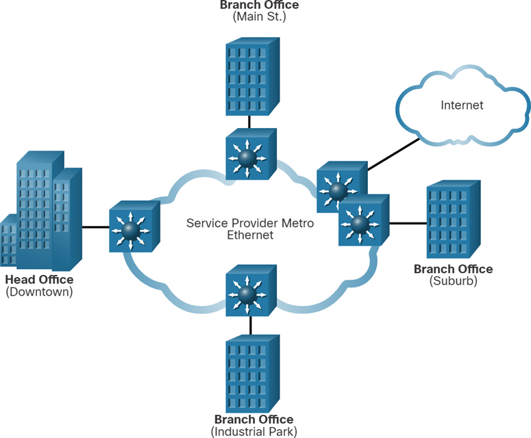
Figure 7-23 Sample Metro Ethernet Topology
The following are several benefits of an Ethernet WAN:
Reduced expenses and administration: An Ethernet WAN provides a switched, high-bandwidth Layer 2 network capable of managing data, voice, and video all on the same infrastructure. This increases bandwidth and eliminates expensive conversions to other WAN technologies. The technology enables businesses to inexpensively connect numerous sites in a metropolitan area to each other and to the internet.
Easy integration with existing networks: An Ethernet WAN connects easily to existing Ethernet LANs, reducing installation costs and time.
Enhanced business productivity: An Ethernet WAN enables businesses to take advantage of productivity-enhancing IP applications that are difficult to implement on TDM or Frame Relay networks, such as hosted IP communications, VoIP, and streaming and broadcast video.
Note
Ethernet WANs have gained in popularity and are now commonly being used to replace the traditional serial point-to-point, Frame Relay, and ATM WAN links.
MPLS (7.4.4)
Multiprotocol Label Switching (MPLS) is a high-performance service provider WAN routing technology to interconnect clients without regard to access method or payload. MPLS supports a variety of client access methods (for example, Ethernet, DSL, cable, Frame Relay). MPLS can encapsulate all types of protocols, including IPv4 and IPv6 traffic.
The sample topology in Figure 7-24 is a simple MPLS-enabled network.
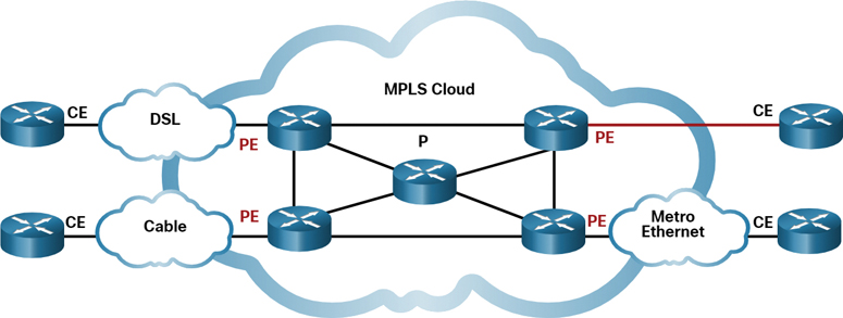
Figure 7-24 Sample MPLS Topology
An MPLS router can be a customer edge (CE) router, a provider edge (PE) router, or an internal provider (P) router. Notice that MPLS supports a variety of client access connections.
MPLS routers are label switched routers (LSRs). This means that they attach labels to packets that are then used by other MPLS routers to forward traffic. When traffic is leaving the CE, the MPLS PE router adds a short fixed-length label in between the frame header and the packet header. MPLS P routers use the label to determine the next hop of the packet. The label is removed by the egress PE router when the packet leaves the MPLS network.
MPLS also provides services for QoS support, traffic engineering, redundancy, and VPNs.
Check Your Understanding—Modern WAN Connectivity (7.4.5)
Refer to the online course to complete this activity.
Internet-Based Connectivity (7.5)
This section discusses the different internet-based connectivity services available.
Internet-Based Connectivity Options (7.5.1)
Modern WAN connectivity options do not end with Ethernet WAN and MPLS. Today, there are a host of internet-based wired and wireless options from which to choose. Internet-based broadband connectivity is an alternative to using dedicated WAN options.
Figure 7-25 lists the internet-based connectivity options.
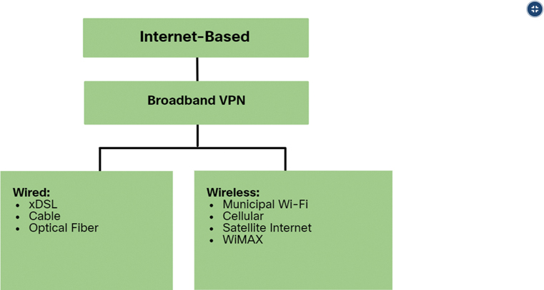
Figure 7-25 Internet-Based Connectivity Options
Internet-based connectivity can be divided into wired and wireless options.
Wired Options
Wired options use permanent cabling (such as copper or fiber) to provide consistent bandwidth and reduce error rates and latency. Examples of wired broadband connectivity are digital subscriber line (DSL), cable connections, and optical fiber networks.
Wireless Options
Wireless options are less expensive to implement compared to other WAN connectivity options because they use radio waves instead of wired media to transmit data. However, wireless signals can be negatively affected by factors such as distance from radio towers, interference from other sources, weather, and the number of users accessing the shared space. Examples of wireless broadband include cellular 3G/4G/5G and satellite internet services. Wireless carrier options vary depending on location.
DSL Technology (7.5.2)
Digital subscriber line (DSL) is a high-speed, always-on connection technology that uses existing twisted-pair telephone lines to provide IP services to users. DSL is a popular choice for home users and for enterprise IT departments to support teleworkers.
Figure 7-26 shows a representation of bandwidth space allocation on a copper wire for asymmetric DSL (ADSL).
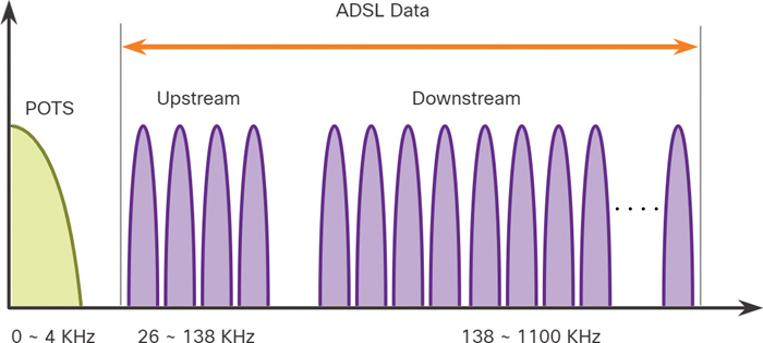
Figure 7-26 DSL Bandwidth Space Allocation
The area of the figure labeled POTS (plain old telephone system) identifies the frequency range used by the voice-grade telephone service. The area labeled ADSL represents the frequency space used by the upstream and downstream DSL signals. The area that encompasses both the POTS area and the ADSL area represents the entire frequency range supported by the copper wire pair.
There are several xDSL varieties offering different upload and download transmission rates. However, all forms of DSL are categorized as either asymmetric DSL (ADSL) or symmetric DSL (SDSL). ADSL and ADSL2+ provide higher downstream bandwidth to the user than upload bandwidth. SDSL provides the same capacity in both directions.
The transfer rates are also dependent on the actual length of the local loop and the type and condition of the cabling. For example, an ADSL loop must be less than 5.46 km (3.39 miles) for guaranteed signal quality.
Security risks are incurred with DSL technology but can be mediated with security measures such as VPNs.
DSL Connections (7.5.3)
Service providers deploy DSL connections in the local loop. As shown in Figure 7-27, a connection is set up between the DSL modem and the DSL access multiplexer (DSLAM).
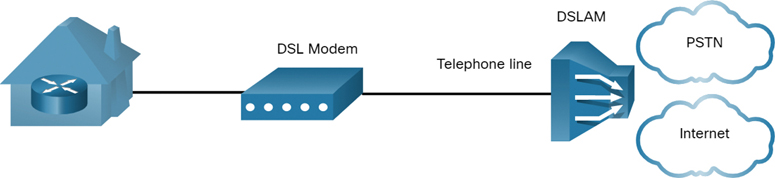
Figure 7-27 Example of a DSL Connection
A DSL modem converts the Ethernet signals from the teleworker device to a DSL signal, which is transmitted to a DSLAM at the provider location.
A DSLAM is the device located at the CO of the provider and concentrates connections from multiple DSL subscribers. A DSLAM is often built into an aggregation router.
The advantage that DSL has over cable technology is that DSL is not a shared medium. Each user has a separate direct connection to the DSLAM. Adding users does not impede performance, unless the DSLAM internet connection to the ISP or to the internet becomes saturated.
DSL and PPP (7.5.4)
Point-to-Point Protocol (PPP) is a Layer 2 protocol that was commonly used by telephone service providers to establish router-to-router and host-to-network connections over dialup and ISDN access networks.
ISPs still use PPP as the Layer 2 protocol for broadband DSL connections for several reasons:
PPP can be used to authenticate the subscriber.
PPP can assign a public IPv4 address and/or IPv6 prefix to the subscriber.
PPP provides link-quality management features.
In PPP over Ethernet (PPPoE), a DSL modem has a DSL interface to connect to the DSL network and an Ethernet interface to connect to the client device. However, Ethernet links do not natively support PPP.
Host with PPPoE Client
In the example in Figure 7-28, the host runs a PPPoE client to obtain a public IPv4 address and/or IPv6 prefix from a PPPoE server located at the provider site. The PPPoE client software communicates with the DSL modem using PPPoE, and the modem communicates with the ISP using PPP. In this topology, only one client can use the connection. Also, notice that there is no router to protect the inside network.

Figure 7-28 Example of a Host with PPPoE Client
Router PPPoE Client
Another solution is to configure a router to be a PPPoE client, as shown in Figure 7-29. The router is the PPPoE client and obtains its configuration from the provider. The clients communicate with the router using only Ethernet and are unaware of the DSL connection. In this topology, multiple clients can share the DSL connection.
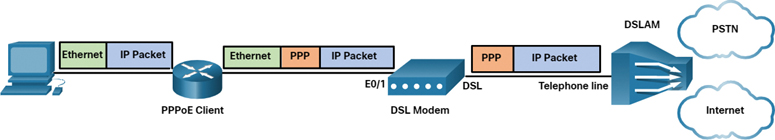
Figure 7-29 Example of a Router PPPoE Client
Cable Technology (7.5.5)
Cable technology is a high-speed always-on connection technology that uses a coaxial cable from the cable company to provide IP services to users. Like DSL, cable technology is a popular choice for home users and for enterprise IT departments to support remote workers.
Modern cable systems offer customers advanced telecommunications services, including high-speed internet access, digital cable television, and residential telephone service.
Data over Cable Service Interface Specification (DOCSIS) is the international standard for adding high-bandwidth data to an existing cable system.
Cable operators deploy hybrid fiber-coaxial (HFC) networks to enable high-speed transmission of data to cable modems. The cable system uses a coaxial cable to carry radio frequency (RF) signals to the end user.
HFC uses fiber-optic and coaxial cable in different portions of the network. For example, the connection between the cable modem and optical node is coaxial cable, as shown in Figure 7-30.

Figure 7-30 Example of Cable Technology Connections
The optical node performs optical-to-RF signal conversion. Specifically, it converts RF signals to light pulses over fiber-optic cable. The fiber media enables the signals to travel over long distances to the provider headend, where a cable modem termination system (CMTS) is located. The headend contains the databases needed to provide internet access, and the CMTS is responsible for communicating with the cable modems.
All the local subscribers share the same cable bandwidth. As more users join the service, available bandwidth may drop below the expected rate.
Optical Fiber (7.5.6)
Many municipalities, cities, and providers install fiber-optic cable to the user location. This is commonly referred to as fiber-to-the-x (FTTx) and includes the following:
Fiber-to-the-home (FTTH): Fiber reaches the boundary of the residence. Passive optical networks and point-to-point Ethernet are architectures that can deliver cable TV, internet, and phone services over FTTH networks directly from the service provider central office.
Fiber-to-the-building (FTTB): Fiber reaches the boundary of the building, such as the basement in a multi-dwelling unit, with the final connection to the individual living space being made via alternative means, like curb or pole technologies.
Fiber-to-the-node/neighborhood (FTTN): Optical cabling reaches an optical node that converts optical signals to a format acceptable for twisted pair or coaxial cable to the premises.
FTTx can deliver the highest bandwidth of all broadband options.
Wireless Internet-Based Broadband (7.5.7)
Wireless technology uses the unlicensed radio spectrum to send and receive data. The unlicensed spectrum is accessible to anyone who has a wireless router and wireless technology in the device he or she is using.
Until recently, one limitation of wireless access has been the need to be within the local transmission range (typically less than 100 feet) of a wireless router or a wireless modem with a wired connection to the internet.
Municipal Wi-Fi
Many cities have begun setting up municipal wireless networks. Some of these networks provide high-speed internet access for free or for substantially less than the price of other broadband services. Others are for city use only, allowing police and fire departments and other city employees to do certain aspects of their jobs remotely. To connect to municipal Wi-Fi, a subscriber typically needs a wireless modem, which provides a stronger radio and directional antenna than conventional wireless adapters. Most service providers provide the necessary equipment for free or for a fee, much as they do with DSL or cable modems.
Cellular
Increasingly, cellular service is another wireless WAN technology being used to connect users and remote locations where no other WAN access technology is available. Many users with smartphones and tablets can use cellular data to email, surf the web, download apps, and watch videos.
Phones, tablet computers, laptops, and even some routers can communicate through the internet using cellular technology. These devices use radio waves to communicate through a nearby mobile phone tower. The device has a small radio antenna, and the provider has a much larger antenna sitting at the top of a tower somewhere within miles of the phone.
The following are two common cellular industry terms:
3G/4G/5G wireless: These are abbreviations for third-generation, fourth-generation, and the emerging fifth-generation mobile wireless technologies. These technologies support wireless internet access. The 4G standard supports bandwidths up to 450 Mbps download and 100 Mbps upload. The emerging 5G standard should support 100 Mbps to 10 Gbps and beyond.
Long-Term Evolution (LTE): This newer and faster technology is part of 4G technology.
Satellite Internet
Satellite internet is typically used by rural users and in remote locations where cable and DSL are not available. To access satellite internet services, subscribers need a satellite dish, two modems (uplink and downlink), and coaxial cables between the dish and the modem.
Specifically, a router connects to a satellite dish that is pointed to a service provider satellite. This satellite is in geosynchronous orbit in space. The signals must travel approximately 35,786 kilometers (22,236 miles) to the satellite and back.
The primary installation requirement is for the antenna to have a clear view toward the equator, where most orbiting satellites are stationed. Trees and heavy rains can affect signal reception.
Satellite internet provides two-way (upload and download) data communications. Upload speeds are about one-tenth of the download speed. Download speeds range from 5 Mbps to 25 Mbps.
WiMAX
Worldwide Interoperability for Microwave Access (WiMAX), described in the IEEE standard 802.16, provides high-speed broadband service with wireless access and provides broad coverage like a cellphone network rather than through small Wi-Fi hotspots.
WiMAX operates in a similar way to Wi-Fi but at higher speeds, over greater distances, and for a greater number of users. It uses a network of WiMAX towers that are like cellphone towers. To access a WiMAX network, users must subscribe to an ISP with a WiMAX tower that is within 30 miles of their location. They also need some type of WiMAX receiver and a special encryption code to get access to the base station.
WiMAX has largely been replaced by LTE for mobile access and by cable or DSL for fixed access.
VPN Technology (7.5.8)
Security risks are incurred when a teleworker or a remote office worker uses a broadband service to access the corporate WAN over the internet.
To address security concerns, broadband services provide virtual private network (VPN) connections to a network device that accepts VPN connections. The network device is typically located at the corporate site.
A VPN is an encrypted connection between private networks over a public network, such as the internet. Instead of using a dedicated Layer 2 connection, such as a leased line, a VPN uses virtual connections called VPN tunnels. VPN tunnels are routed through the internet from the private network of the company to the remote site or employee host.
The following are several benefits to using VPN:
Cost savings: VPNs enable organizations to use the global internet to connect remote offices and to connect remote users to the main corporate site. This eliminates the need for expensive, dedicated WAN links and modem banks.
Security: VPNs provide the highest level of security by using advanced encryption and authentication protocols that protect data from unauthorized access.
Scalability: Because VPNs use the internet infrastructure within ISPs and devices, it is easy to add new users. Corporations can add large amounts of capacity without adding significant infrastructure.
Compatibility with broadband technology: VPN technology is supported by broadband service providers such as DSL and cable. VPNs allow mobile workers and telecommuters to take advantage of their home high-speed internet service to access their corporate networks. Business-grade, high-speed broadband connections can also provide a cost-effective solution for connecting remote offices.
VPNs are commonly implemented as the following:
Site-to-site VPN: VPN settings are configured on routers. Clients are unaware that their data is being encrypted.
Remote access VPN: The user initiates remote-access connection (such as by using HTTPS in a browser to connect to the bank). Alternatively, the user can run VPN client software on his or her host to connect to and authenticate with the destination device.
Note
VPNs are discussed in more detail in Chapter 8, “VPN and IPsec Concepts.”
ISP Connectivity Options (7.5.9)
This section explains the different ways an organization can connect to an ISP. The choice depends on the needs and budget of the organization.
Single-Homed
Single-homed ISP connectivity is used by the organization when internet access is not crucial to the operation. As shown in Figure 7-31, the client connects to the ISP using one link. This topology provides no redundancy, and it is the least expensive solution of the four described in this section.
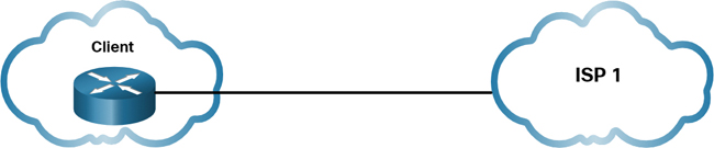
Figure 7-31 Single-Homed Example
Dual-Homed
Dual-homed ISP connectivity is used by an organization when internet access is somewhat crucial to the operation. As shown in Figure 7-32, the client connects to the same ISP using two links. The topology provides both redundancy and load balancing. If one link fails, the other link can carry the traffic. If both links are operational, traffic can be load balanced over them. However, the organization loses internet connectivity if the ISP experiences an outage.

Figure 7-32 Dual-Homed Example
Multihomed
Multihomed ISP connectivity is used by an organization when internet access is crucial to the operation. The client connects to two different ISPs, as shown in Figure 7-33. This design provides increased redundancy and enables load balancing, but it can be expensive.

Figure 7-33 Multihomed Example
Dual-Multihomed
Dual-multihomed ISP is the most resilient topology of the four described in this section. The client connects with redundant links to multiple ISPs, as shown in Figure 7-34. This topology provides the most redundancy possible, and it is the most expensive option of the four.

Figure 7-34 Dual-Multihomed Example
Broadband Solution Comparison (7.5.10)
Each broadband solution has advantages and disadvantages. The ideal solution is to have a fiber-optic cable directly connected to a client network. Some locations have only one option, such as cable or DSL. Some locations have only broadband wireless options for internet connectivity.
If there are multiple broadband solutions available, a cost-versus-benefit analysis should be performed to determine the best solution.
Some factors to consider include the following:
Cable: Bandwidth is shared by many users. Therefore, upstream data rates are often slow during high-usage hours in areas with oversubscription.
DSL: DSL has limited bandwidth and is distance sensitive (in relation to the ISP central office). The upload rate is proportionally lower than the download rate.
Fiber-to-the-home: This option requires fiber installation directly to the home.
Cellular/mobile: With this option, coverage is often an issue, even within a small office or home office where bandwidth is relatively limited.
Municipal Wi-Fi: Most municipalities do not have a mesh Wi-Fi network deployed. If municipal Wi-Fi is available and in range, however, it is a viable option.
Satellite: This option is expensive and provides limited capacity per subscriber. It is typically used when no other option is available.
Lab—Research Broadband Internet Access Options (7.5.11)
![]()
In this lab, you will complete the following objectives:
Part 1: Investigate broadband distribution
Part 2: Research broadband access options for specific scenarios
Summary (7.6)
The following is a summary of the sections in this chapter.
Purpose of WANs
A wide-area network (WAN) is required to connect beyond the boundaries of a LAN. A WAN is a telecommunications network that spans a relatively large geographic area. A WAN operates beyond the geographic scope of a LAN. A private WAN is a connection that is dedicated to a single customer. A public WAN connection is typically provided by an ISP or a telecommunications service provider using the internet. A WAN topology is described using a logical topology. WANs are implemented using the following logical topologies: point-to-point, hub-and-spoke, dual-homed, fully meshed, and partially meshed. With a single-carrier connection, an organization connects to only one service provider. A dual-carrier connection provides redundancy and increases network availability. The organization negotiates separate SLAs with two different service providers. Network requirements of a company can change dramatically as the company grows over time. Distributing employees saves costs in many ways, but it puts increased demands on the network. Small companies may use a single LAN connected to a wireless router to share data and peripherals. Connection to the internet is through a broadband service provider. A slightly larger company may use a campus-area network (CAN), which interconnects several LANs within a limited geographic area. An even larger company may require a metropolitan-area network (MAN) to interconnect sites within the city. A MAN is larger than a LAN but smaller than a WAN. A global company may require teleworking and virtual teams using web-based applications, including web conferencing, e-learning, and online collaboration tools. Site-to-site and remote-access virtual private networks (VPNs) enable a company to use the internet to securely connect with employees and facilities around the world.
WAN Operations
Modern WAN standards are defined and managed by a number of recognized authorities, including TIA/EIA, ISO, and IEEE. Most WAN standards focus on the physical layer (OSI Layer 1) and the data link layer (OSI Layer 2). Layer 1 protocols describe the electrical, mechanical, and operational components needed to transmit bits over a WAN. Layer 1 optical fiber protocol standards include SDH, SONET, and DWDM. Layer 2 protocols define how data is encapsulated into a frame. Layer 2 protocols include broadband, wireless, Ethernet WAN, MPLS, PPP, and HDLC. The WAN physical layer describes the physical connections between a company network and a service provider network. There are specific terms used to describe WAN connections between the subscriber (that is, the company/client) and a WAN service provider, including DTE, DCE, CPE, POP, demarcation point, local loop, CO, toll network, backhaul network, and backbone network. The end-to-end data path over a WAN is usually from source DTE to the DCE, then to the WAN cloud, then to the DCE, and finally to the destination DTE. Devices used in this path include voiceband modems, DSL and cable modems, CSUs/DSUs, optical converters, wireless routers or access points, and other WAN core devices. Serial communication transmits bits sequentially over a single channel. In contrast, parallel communications simultaneously transmit several bits using multiple wires. A circuit-switched network establishes a dedicated circuit (or channel) between endpoints before the users can communicate. During transmission over a circuit-switched network, all communication uses the same path. The two most common types of circuit-switched WAN technologies are PSTN and ISDN. Packet-switching segments traffic data into packets that are routed over a shared network. Common types of packet-switched WAN technologies are Ethernet WAN and MPLS. There are two optical fiber OSI Layer 1 standards. SDH/SONET define how to transfer multiple data, voice, and video communications over optical fiber using lasers or LEDs over great distances. Both standards are used on the ring network topology, which contains redundant fiber paths allowing traffic to flow in both directions. DWDM is a newer technology that increases the data-carrying capacity of SDH and SONET by simultaneously sending multiple streams of data (multiplexing) using different wavelengths of light.
Traditional WAN Connectivity
In the 1980s, organizations started to see the need to interconnect their LANs with other locations. They needed their networks to connect to the local loop of a service provider by using dedicated lines or by using switched services from a service provider. When permanent dedicated connections were required, a point-to-point link using copper media was used to provide a preestablished WAN communications path from the customer premises to the provider network. Dedicated leased lines were T1/E1 or T3/E3 lines. Circuit-switched connections were provided by PSTN carriers. The local loop connecting the CPE to the CO was copper media. ISDN is a circuit-switching technology that enables the PSTN local loop to carry digital signals. It provided higher-capacity switched connections than dialup access. Packet switching segments data into packets that are routed over a shared network. Packet-switching networks allow many pairs of nodes to communicate over the same channel. Frame Relay is a simple Layer 2 NBMA WAN technology used to interconnect enterprise LANs. ATM technology is capable of transferring voice, video, and data through private and public networks. It is built on a cell-based architecture rather than on a frame-based architecture.
Modern WAN Connectivity
Modern WAN connectivity options include dedicated broadband, Ethernet WAN, and MPLS (packet switched), along with various wired and wireless versions of internet-based broadband. Service providers now offer Ethernet WAN service using fiber-optic cabling. Ethernet WAN reduces expenses and administration, is easily integrated with existing networks, and enhances business productivity. MPLS is a high-performance service provider WAN routing technology for interconnecting clients. MPLS supports a variety of client access methods (such as Ethernet, DSL, cable, and Frame Relay). MPLS can encapsulate all types of protocols, including IPv4 or IPv6 traffic.
Internet-Based Connectivity
Internet-based broadband connectivity is an alternative to using dedicated WAN options. There are wired and wireless versions of broadband VPN. Wired options use permanent cabling (such as copper or fiber) to provide consistent bandwidth and reduce error rates and latency. Examples of wired broadband connectivity are digital subscriber line (DSL), cable connections, and optical fiber networks. Examples of wireless broadband include cellular 3G/4G/5G and satellite internet services. DSL is a high-speed, always-on connection technology that uses existing twisted-pair telephone lines to provide IP services to users. All forms of DSL are categorized as either ADSL or SDSL. A DSL modem converts Ethernet signals from a teleworker’s device to a DSL signal, which is transmitted to a DSLAM at the provider location. The advantage that DSL has over cable technology is that DSL is not a shared medium. ISPs still use PPP as the Layer 2 protocol for broadband DSL connections. A DSL modem has a DSL interface to connect to the DSL network and an Ethernet interface to connect to the client device. Ethernet links do not natively support PPP. Cable technology is a high-speed always-on connection technology that uses a cable company coaxial cable to provide IP services to users. Cable operators deploy hybrid fiber-coaxial (HFC) networks to enable high-speed transmission of data to cable modems. The cable system uses a coaxial cable to carry radio frequency (RF) signals to the end user. Many municipalities, cities, and providers install fiber-optic cable to the user location. This is commonly referred to as fiber-to-the-x (FTTx), such as FTTH, FTTB, and FTTN.
Wireless technology uses the unlicensed radio spectrum to send and receive data. The unlicensed spectrum is accessible to anyone who has a wireless router and wireless technology in the device he or she is using. Until recently, one limitation of wireless access has been the need to be within the local transmission range (typically less than 100 feet) of a wireless router or a wireless modem that has a wired connection to the internet. Newer developments in wireless technology include municipal Wi-Fi, cellular, satellite internet, and WiMAX. To address security concerns, broadband services provide capabilities for using virtual private network (VPN) connections to a network device that accepts VPN connections, which is typically located at the corporate site. A VPN is an encrypted connection between private networks over a public network, such as the internet. Instead of using a dedicated Layer 2 connection, such as a leased line, a VPN uses virtual connections called VPN tunnels. VPN tunnels are routed through the internet from the private network of the company to the remote site or employee host. Common VPN implementations include site-to-site and remote-access VPNs. ISP connectivity options include single-homed, dual-homed, multihomed, and dual-multihomed. Cable, DSL, fiber-to-the-home, cellular/mobile, municipal Wi-Fi, and satellite internet all have advantages and disadvantages. Perform a cost-versus-benefit analysis before choosing an internet-based connectivity solution.
Packet Tracer—WAN Concepts (7.6.1)

In this Packet Tracer activity, you will explore various WAN technologies and implementations.
Practice
The following activities provide practice with the topics introduced in this chapter. The labs are available in the companion Enterprise Networking, Security, and Automation v7 Labs & Study Guide (ISBN 9780136634690). The Packet Tracer activity instructions are also in the Labs & Study Guide. The PKA files are found in the online course.
Lab
![]()
Lab 7.5.11: Research Broadband Internet Access Options
Packet Tracer Activity
Packet Tracer 7.6.1: WAN Concepts
Check Your Understanding Questions
Complete all the review questions listed here to test your understanding of the topics and concepts in this chapter. The appendix “Answers to ‘Check Your Understanding’ Questions” lists the answers.
1. Which type of internet connection would be suitable for a small 10-employee company with one local LAN?
A broadband DSL or cable connection to a service provider
A dialup connection to the local telephone service provider
A private dedicated line to the local service provider
A VSAT connection to a service provider
2. Which network scenario requires the use of a WAN?
Employee workstations need to obtain dynamically assigned IP addresses.
Employees in the branch office need to share files with the headquarters office that is located in a separate building on the same campus network.
Employees need to access web pages that are hosted on the corporate web servers in the DMZ within their building.
Traveling employees must connect to the corporate email server using a VPN.
3. Which statement is true of a WAN?
A WAN operates within the same geographic scope as a LAN but has serial links.
A WAN provides end-user network connectivity to the campus backbone.
All serial links are considered WAN connections.
WAN networks are owned by service providers.
4. Which device is needed when a digital leased line is used to provide a connection between a customer and a service provider?
Access server
CSU/DSU
Dialup modem
Layer 2 switch
5. What is a requirement of a connectionless packet-switched network?
A virtual circuit is created for the duration of the packet delivery.
Each packet has to carry only an identifier.
Full addressing information must be carried in each data packet.
The network predetermines the route for a packet.
6. What is an advantage of packet-switching technology over circuit-switching technology?
Packet-switched networks are less susceptible to jitter than circuit-switched networks.
Packet-switched networks can efficiently use multiple routes inside a service provider network.
Packet-switched networks require an expensive permanent connection to each endpoint.
Packet-switched networks usually experience lower latency than circuit-switched networks experience.
7. What is a long-distance fiber-optic media technology that supports both SONET and SDH and assigns incoming optical signals to specific wavelengths of light?
ATM
DWDM
ISDN
MPLS
8. What is the recommended technology to use over a public WAN infrastructure when a branch office is connected to a corporate site?
ATM
ISDN
Municipal Wi-Fi
VPN
9. What are two common high-bandwidth fiber-optic media standards? (Choose two.)
ANSI
ATM
ITU
SDH
SONET
10. Which WAN technology establishes a dedicated constant point-to-point connection between two sites?
ATM
Frame Relay
ISDN
Leased lines
11. A hospital is looking for a solution to connect multiple newly established remote branch medical offices. Which of the following is most important when selecting a private WAN connection rather than a public WAN connection?
Data security and confidentiality during transmission
Higher data transmission rate
Lower cost
Website and file exchange service support
12. A new corporation needs a data network that must meet certain requirements. The network must provide a low-cost connection to salespeople dispersed over a large geographic area. Which two types of WAN infrastructure would meet the requirements? (Choose two.)
Dedicated
Internet
Private infrastructure
Public infrastructure
Satellite
13. Which wireless technology provides internet access through cellular networks?
Bluetooth
LTE
Municipal Wi-Fi
Satellite
14. Which equipment is needed for an ISP to provide internet connections through cable service?
Access server
CMTS
CSU/DSU
DSLAM
15. A customer needs a WAN virtual connection that provides high-speed, dedicated bandwidth between two sites. Which type of WAN connection would best fulfill this need?
Circuit-switched network
Ethernet WAN
MPLS
Packet-switched network