Chapter 9
QoS Concepts
Objectives
Upon completion of this chapter, you will be able to answer the following questions:
How do network transmission characteristics impact quality?
What are the minimum network requirements for voice, video, and data traffic?
What queuing algorithms do networking devices use?
What are the different QoS models?
What QoS mechanisms ensure transmission quality?
Key Terms
This chapter uses the following key terms. You can find the definitions in the Glossary.
digital signal processor (DSP) page 357
Cisco Visual Networking Index (VNI) page 357
first-in, first-out (FIFO) page 361
Weighted Fair Queuing (WFQ) page 361
Class-Based Weighted Fair Queuing (CBWFQ) page 361
Low Latency Queuing (LLQ) page 361
Type of Service (ToS) page 363
Integrated Services (IntServ) page 366
Differentiated Services (DiffServ) page 366
Resource Reservation Protocol (RSVP) page 368
weighted random early detection (WRED) page 371
Network Based Application Recognition (NBAR) page 372
Class of Service (CoS) page 373
Differentiated Services Code Point (DSCP) page 373
Tag Control Information (TCI) field page 373
Type of Service (ToS) field page 374
Expedited Forwarding (EF) page 376
Introduction (9.0)
Imagine driving on a heavily congested road and being in a rush to meet a friend for dinner. You hear the siren and see the lights of an ambulance behind you. You need to move off the road to let the ambulance through. The ambulance getting to the hospital takes priority over you getting to the restaurant on time.
Much like the ambulance taking priority in the traffic on the highway, some forms of network traffic need priority over others. Why? Get started with this chapter to find out!
Network Transmission Quality (9.1)
In this section, you will learn how network transmission characteristics impact quality.
Video Tutorial—The Purpose of QoS (9.1.1)

Refer to the online course to view this video.
Prioritizing Traffic (9.1.2)
Quality of service (QoS) is an ever-increasing requirement of networks today. New applications, such as voice and live video transmissions, create higher expectations for quality delivery among users.
Congestion occurs when multiple communication lines aggregate onto a single device such as a router and then much of that data is placed on just a few outbound interfaces or onto a slower interface. Congestion can also occur when large data packets prevent smaller packets from being transmitted in a timely manner.
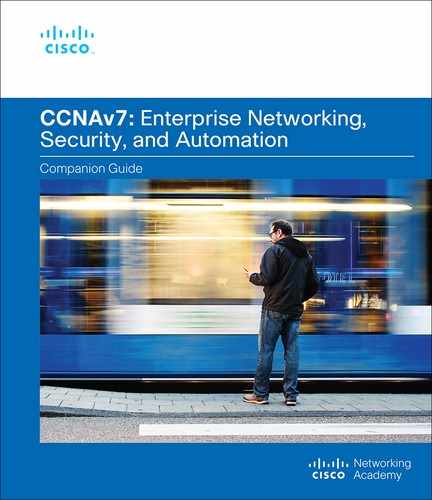
When the volume of traffic is greater than what can be transported across the network, devices queue (hold) the packets in memory until resources become available to transmit them. Queuing packets causes delay because new packets cannot be transmitted until previous packets have been processed. If the number of packets queued continues to increase, the memory within the device fills up, and the device drops packets. One QoS technique that can help with this problem is to classify data into multiple queues, as shown in Figure 9-1.
Note
A device implements QoS only when it is experiencing some type of congestion.
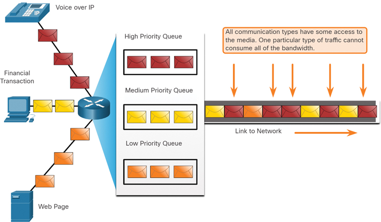
Figure 9-1 Using Queues to Prioritize Communications
Bandwidth, Congestion, Delay, and Jitter (9.1.3)
Network bandwidth is measured in the number of bits that can be transmitted in a single second, or bits per second (bps). For example, a network device may be described as having the capability to perform at 10 gigabits per second (Gbps).
Network congestion causes delay. An interface experiences congestion when it is presented with more traffic than it can handle. Network congestion points are ideal candidates for QoS mechanisms. Figure 9-2 shows three examples of typical congestion points.
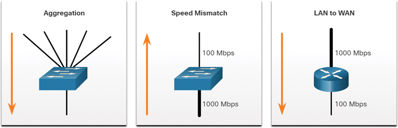
Figure 9-2 Examples of Congestion Points
Delay, or latency, refers to the time it takes for a packet to travel from the source to the destination. Two types of delays are fixed and variable. A fixed delay is a specific amount of time a specific process takes, such as how long it takes to place a bit on the transmission media. A variable delay takes an unspecified amount of time and is affected by factors such as how much traffic is being processed.
The types of delay are summarized in Table 9-1.
Table 9-1 Types of Delay
Delay Type |
Description |
Code delay |
The fixed amount of time it takes to compress data at the source before transmitting to the first internetworking device, usually a switch. |
Packetization delay |
The fixed time it takes to encapsulate a packet with all the necessary header information. |
Queuing delay |
The variable amount of time a frame or packet waits to be transmitted on the link. |
Serialization delay |
The fixed amount of time it takes to transmit a frame onto the wire. |
Propagation delay |
The variable amount of time it takes for a frame to travel between the source and destination. |
De-jitter delay |
The fixed amount of time it takes to buffer a flow of packets and then send them out in evenly spaced intervals. |
Jitter is the variation in the delay of received packets. At the sending side, packets are sent in a continuous stream, with the packets spaced evenly apart. Due to network congestion, improper queuing, or configuration errors, the delay between packets can vary instead of remaining constant. Both delay and jitter need to be controlled and minimized to support real-time and interactive traffic.
Packet Loss (9.1.4)
Without any QoS mechanisms in place, packets are processed in the order in which they are received. When congestion occurs, network devices such as routers and switches can drop packets. This means that time-sensitive packets, such as real-time video and voice, will be dropped with the same frequency as data that is not time sensitive, such as email and web browsing.
When a router receives a Real-Time Protocol (RTP) digital audio stream for voice over IP (VoIP), it must compensate for the jitter that is encountered. The mechanism that handles this function is the playout delay buffer. This buffer must buffer these packets and then play them out in a steady stream, as shown in Figure 9-3. The digital packets are later converted back to an analog audio stream.
Figure 9-3 Playout Delay Buffer Compensates for Jitter
If the jitter is so severe that it causes packets to be received out of the range of this buffer, the out-of-range packets are discarded, and dropouts are heard in the audio, as shown in Figure 9-4.
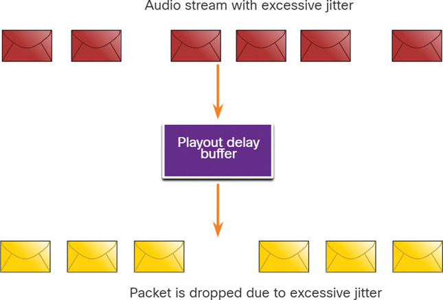
Figure 9-4 Packet Dropped Due to Excessive Jitter
For losses as small as one packet, the digital signal processor (DSP) interpolates what it thinks the audio should be, and no problem is audible to the user. However, when jitter exceeds what the DSP can do to make up for the missing packets, audio problems are heard.
Packet loss is a very common cause of voice quality problems on an IP network. In a properly designed network, packet loss should be near zero. The voice codecs used by the DSP can tolerate some degree of packet loss without a dramatic effect on voice quality. Network engineers use QoS mechanisms to classify voice packets for zero packet loss. Bandwidth is guaranteed for the voice calls by giving priority to voice traffic over traffic that is not sensitive to delays.
Check Your Understanding—Network Transmission Quality (9.1.5)

Refer to the online course to complete this activity.
Traffic Characteristics (9.2)
In this section, you will learn about the minimum network requirements to support voice, video, and data traffic.
Video Tutorial—Traffic Characteristics (9.2.1)
Refer to the online course to view this video.
Network Traffic Trends (9.2.2)
Earlier in this chapter, you learned about network transmission quality. In this section you will learn about traffic characteristics (voice, video, and data). In the early 2000s, the predominant types of IP traffic were voice and data. Voice traffic has a predictable bandwidth need and known packet arrival times. Data traffic is not real time and has unpredictable bandwidth need. Data traffic can temporarily burst, as when a large file is being downloaded. This bursting can consume the entire bandwidth of a link.
More recently, video traffic has become increasingly important to business communications and operations. Consider that organizations now commonly use video conferencing to meet with users and clients, high-definition video surveillance to remotely monitor facilities and equipment, and video streaming for a variety of purposes, including training. According to the Cisco Visual Networking Index (VNI), by 2022 video will represent 82% of all internet traffic. In addition, mobile video traffic will reach 60.9 exabytes per month by 2022.
The type of demands that voice, video, and data traffic place on the network are very different.
Voice (9.2.3)
Voice traffic is predictable and smooth. However, voice is very sensitive to delays and dropped packets. It makes no sense to re-transmit voice if packets are lost; therefore, voice packets must receive a higher priority than other types of traffic. For example, Cisco products use the RTP port range 16,384 to 32,767 to prioritize voice traffic. Voice can tolerate a certain amount of latency, jitter, and loss without any noticeable effects. Latency should be no more than 150 milliseconds (ms). Jitter should be no more than 30 ms, and voice packet loss should be no more than 1%. Voice traffic requires at least 30 kbps of bandwidth. Table 9-2 gives a summary of voice traffic characteristics and requirements.
Table 9-2 Voice Traffic Characteristics
Characteristics |
One-Way Requirements |
|
|
Video (9.2.4)
Without QoS and a significant amount of extra bandwidth capacity, video quality typically degrades. The picture appears blurry, jagged, or too slow. The audio portion of the feed may become unsynchronized with the video.
Video traffic tends to be unpredictable, inconsistent, and bursty compared to voice traffic. Compared to voice, video is less resilient to loss and has a higher volume of data per packet. Notice in Figure 9-5 that voice packets arrive every 20 ms and are a predictable 200 bytes each.
In contrast, the number and size of video packets vary every 33 ms, based on the content of the video, as shown in Figure 9-6.
For example, if the video stream consists of content that is not changing much from frame to frame, the video packets are small, and fewer of them are required to maintain acceptable user experience. However, if the video steam consists of content that is rapidly changing, such as an action sequence in a movie, the video packets are larger, and more of them are required per the 33 ms time slot to maintain an acceptable user experience.
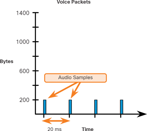
Figure 9-5 Voice Packet Size and Timing
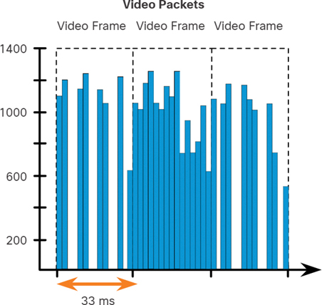
Figure 9-6 Video Packet Size and Timing
UDP ports such as 554 are used for the Real-Time Streaming Protocol (RTSP) and should be given priority over other, less delay-sensitive, network traffic. Similar to voice, video can tolerate a certain amount of latency, jitter, and loss without any noticeable effects. Latency should be no more than 400 milliseconds (ms). Jitter should be no more than 50 ms, and video packet loss should be no more than 1%. Video traffic requires at least 384 kbps of bandwidth. Table 9-3 gives a summary of video traffic characteristics and requirements.
Table 9-3 Video Traffic Characteristics
Characteristics |
One-Way Requirements |
|
|
Data (9.2.5)
Most applications use either TCP or UDP. Unlike UDP, TCP performs error recovery. Data applications that have no tolerance for data loss, such as email and web pages, use TCP to ensure that, if packets are lost in transit, they are re-sent. Data traffic can be smooth or bursty. Network control traffic is usually smooth and predictable. When there is a topology change, the network control traffic may burst for a few seconds. But the capacity of today’s networks can easily handle the increase in network control traffic as the network converges.
However, some TCP applications can consume a large portion of network capacity. For example, FTP consumes as much bandwidth as it can get when you download a large file, such as a movie or game. Table 9-4 summarizes data traffic characteristics.
Table 9-4 Data Traffic Characteristics
|
Although data traffic is relatively insensitive to drops and delays compared to voice and video, a network administrator still needs to consider the quality of the user experience, sometimes referred to as quality of experience (QoE). There are two main factors that a network administrator needs to consider about the flow of data traffic:
Does the data come from an interactive application?
Is the data mission critical?
Table 9-5 compares these two factors.
Table 9-5 Factors to Consider for Data Delay
Factor |
Mission Critical |
Not Mission Critical |
Interactive |
Prioritize for the lowest delay of all data traffic and strive for a 1- to 2-second response time. |
Applications could benefit from lower delay. |
Not interactive |
Delay can vary greatly as long as the necessary minimum bandwidth is supplied. |
Gets any leftover bandwidth after all voice, video, and other data application needs are met. |
Check Your Understanding—Traffic Characteristics (9.2.6)
Refer to the online course to complete this activity.
Queuing Algorithms (9.3)
The previous section covers traffic characteristics. This section explains the queuing algorithms used to implement QoS.
Video Tutorial—QoS Algorithms (9.3.1)
Refer to the online course to view this video.
Queuing Overview (9.3.2)
The QoS policy implemented by a network administrator becomes active when congestion occurs on the link. Queuing is a congestion management tool that can buffer, prioritize, and, if required, reorder packets before they are transmitted to the destination.
A number of queuing algorithms are available. For the purposes of this chapter, we focus on the following:
First-In, First Out (9.3.3)
In its simplest form, first-in, first-out (FIFO) queuing, also known as first-come, first-served queuing, buffers and forwards packets in the order of their arrival.
FIFO has no concept of priority or classes of traffic. Consequently, it makes no decision about packet priority. There is only one queue, and all packets are treated equally. Packets are sent out an interface in the order in which they arrive, as shown in Figure 9-7.
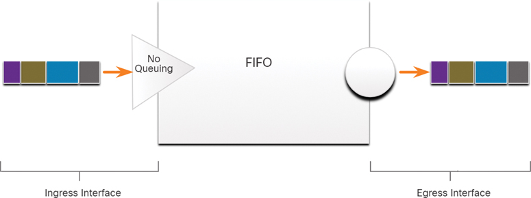
Figure 9-7 FIFO Queuing Example
Although some traffic may be more important or time-sensitive than other traffic, based on the priority classification, notice that the traffic is sent out in the order in which it is received.
When FIFO is used, important or time-sensitive traffic can be dropped when there is congestion on the router or switch interface. When no other queuing strategies are configured, all interfaces except serial interfaces at E1 (2.048 Mbps) and below use FIFO by default. (Serial interfaces at E1 and below use WFQ by default.)
FIFO, which is the fastest method of queuing, is effective for large links that have little delay and minimal congestion. If a link has very little congestion, FIFO queuing may be the only queuing needed.
Weighted Fair Queuing (WFQ) (9.3.4)
Weighted Fair Queuing (WFQ) is an automated scheduling method that provides fair bandwidth allocation to all network traffic. WFQ does not allow classification options to be configured. WFQ applies priority, or weights, to identified traffic and classifies it into conversations or flows, as shown in Figure 9-8.

Figure 9-8 Weighted Fair Queuing Example
WFQ then determines how much bandwidth each flow is allowed, relative to other flows. The flow-based algorithm used by WFQ simultaneously schedules interactive traffic to the front of a queue to reduce response time. It then fairly shares the remaining bandwidth among high-bandwidth flows. WFQ allows you to give low-volume, interactive traffic, such as Telnet sessions and voice, priority over high-volume traffic, such as FTP sessions. When multiple file transfer flows are occurring simultaneously, the transfers are given comparable bandwidth.
WFQ classifies traffic into different flows based on packet header addressing, including characteristics such as source and destination IP addresses, MAC addresses, port numbers, protocol, and Type of Service (ToS) value. The ToS value in the IP header can be used to classify traffic.
Low-bandwidth traffic flows, which comprise the majority of traffic, receive preferential service that allows their entire offered loads to be sent in a timely fashion. High-volume traffic flows share the remaining capacity proportionally among themselves.
Limitations of WFQ
WFQ is not supported with tunneling and encryption because these features modify the packet content information required by WFQ for classification.
Although WFQ automatically adapts to changing network traffic conditions, it does not offer the degree of precise control over bandwidth allocation that CBWFQ offers.
Class-Based Weighted Fair Queuing (CBWFQ) (9.3.5)
Class-Based Weighted Fair Queuing (CBWFQ) extends the standard WFQ functionality to provide support for user-defined traffic classes. With CBWFQ, you define traffic classes based on match criteria including protocols, access control lists (ACLs), and input interfaces. Packets satisfying the match criteria for a class constitute the traffic for that class. A FIFO queue is reserved for each class, and traffic belonging to a class is directed to the queue for that class, as shown in Figure 9-9.
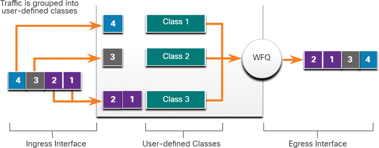
Figure 9-9 CBWFQ Example
When a class has been defined according to its match criteria, you can assign it characteristics. To characterize a class, you assign it bandwidth, weight, and a maximum packet limit. The bandwidth assigned to a class is the guaranteed bandwidth delivered to the class during congestion.
To characterize a class, you also specify the queue limit for that class, which is the maximum number of packets allowed to accumulate in the queue for the class. Packets belonging to a class are subject to the bandwidth and queue limits that characterize the class.
After a queue has reached its configured queue limit, adding more packets to the class causes tail drop or packet drop to occur, depending on how class policy is configured. Tail drop means a router simply discards any packet that arrives at the tail end of a queue that has completely used up its packet-holding resources. This is the default queuing response to congestion. Tail drop treats all traffic equally and does not differentiate between classes of service.
Low Latency Queuing (LLQ) (9.3.6)
The Low Latency Queuing (LLQ) feature brings strict priority queuing (PQ) to CBWFQ. Strict PQ allows delay-sensitive packets such as voice packets to be sent before packets in other queues. LLQ provides strict priority queuing for CBWFQ to reduce jitter in voice conversations, as shown in Figure 9-10.
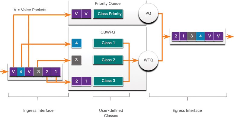
Figure 9-10 LLQ Example
Without LLQ, CBWFQ provides WFQ based on defined classes, with no strict priority queue available for real-time traffic. The weight for a packet belonging to a specific class is derived from the bandwidth you assigned to the class when you configured it. Therefore, the bandwidth assigned to the packets of a class determines the order in which packets are sent. All packets are serviced fairly, based on weight; no class of packets may be granted strict priority. This scheme poses problems for voice traffic that is largely intolerant of delay, especially variation in delay. For voice traffic, variations in delay introduce irregularities of transmission manifesting as jitter in the heard conversation.
LLQ allows delay-sensitive packets such as voice packets to be sent first (before packets in other queues), giving delay-sensitive packets preferential treatment over other traffic. Although it is possible to classify various types of real-time traffic to the strict priority queue, Cisco recommends that only voice traffic be directed to the priority queue.
Check Your Understanding—Queuing Algorithms (9.3.7)
Refer to the online course to complete this activity.
QoS Models (9.4)
In this section, you will learn how networking devices implement QoS.
Video Tutorial—QoS Models (9.4.1)
Refer to the online course to view this video.
Selecting an Appropriate QoS Policy Model (9.4.2)
How can QoS be implemented in a network? There are three models for implementing QoS:
Table 9-6 summarizes these three models. QoS is implemented in a network using either IntServ or DiffServ. While IntServ provides the highest guarantee of QoS, it is very resource intensive, and it is therefore not easily scalable. In contrast, DiffServ is less resource intensive and more scalable. The two are sometimes co-deployed in network QoS implementations.
Table 9-6 Models for Implementing QoS
Model |
Description |
Best-effort model |
|
Integrated Services (IntServ) |
|
Differentiated Services (DiffServ) |
|
Best Effort (9.4.3)
The basic design of the internet is best-effort packet delivery with no guarantees. This approach is still predominant on the internet today and remains appropriate for most purposes. The best-effort model treats all network packets in the same way, so an emergency voice message is treated the same way that a digital photograph attached to an email is treated. Without QoS, the network cannot tell the difference between packets and, as a result, cannot treat packets preferentially.
The best-effort model is similar in concept to sending a letter using standard postal mail. Your letter is treated exactly the same as every other letter. With the best-effort model, the letter may never arrive, and, unless you have a separate notification arrangement with the letter recipient, you may never know that the letter did not arrive.
Table 9-7 lists the benefits and drawbacks of the best-effort model.
Table 9-7 Benefits and Drawbacks of the Best-Effort Model
Benefits |
Drawbacks |
|
|
Integrated Services (9.4.4)
The Integrated Services (IntServ) architecture model (RFCs 1633, 2211, and 2212) was developed in 1994 to meet the needs of real-time applications, such as remote video, multimedia conferencing, data visualization applications, and virtual reality. IntServ is a multiple-service model that can accommodate many QoS requirements.
IntServ delivers the end-to-end QoS that real-time applications require. IntServ explicitly manages network resources to provide QoS to individual flows or streams, sometimes called microflows. It uses resource reservation and admission-control mechanisms as building blocks to establish and maintain QoS. This is similar to a concept known as “hard QoS.” Hard QoS guarantees traffic characteristics, such as bandwidth, delay, and packet-loss rates, from end to end. Hard QoS ensures both predictable and guaranteed service levels for mission-critical applications.
Figure 9-11 shows a simple illustration of the IntServ model.
IntServ uses a connection-oriented approach inherited from telephony network design. Each individual communication must explicitly specify its traffic descriptor and requested resources to the network. The edge router performs admission control to ensure that available resources are sufficient in the network. The IntServ standard assumes that routers along a path set and maintain the state for each individual communication.
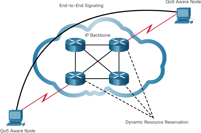
Figure 9-11 Simple IntServ Example
In the IntServ model, the application requests a specific kind of service from the network before sending data. The application informs the network of its traffic profile and requests a particular kind of service that can encompass its bandwidth and delay requirements. IntServ uses Resource Reservation Protocol (RSVP) to signal the QoS needs of an application’s traffic along devices in the end-to-end path through the network. If network devices along the path can reserve the necessary bandwidth, the originating application can begin transmitting. If the requested reservation fails along the path, the originating application does not send any data.
The edge router performs admission control based on information from the application and available network resources. The network commits to meeting the QoS requirements of the application as long as the traffic remains within the profile specifications. The network fulfills its commitment by maintaining the per-flow state and then performing packet classification, policing, and intelligent queuing based on that state.
Table 9-8 lists the benefits and drawbacks of the IntServ model.
Table 9-8 Benefits and Drawbacks of the IntServ Model
Benefits |
Drawbacks |
|
|
Differentiated Services (9.4.5)
The Differentiated Services (DiffServ) QoS model specifies a simple and scalable mechanism for classifying and managing network traffic. For example, DiffServ can provide low-latency guaranteed service to critical network traffic such as voice or video, while providing simple best-effort traffic guarantees to non-critical services such as web traffic or file transfers.
The DiffServ design overcomes the limitations of both the best-effort and IntServ models. The DiffServ model is described in RFCs 2474, 2597, 2598, 3246, and 4594. DiffServ can provide an “almost guaranteed” QoS while still being cost-effective and scalable.
The DiffServ model is similar in concept to sending a package using a delivery service. You request (and pay for) a level of service when you send a package. Throughout the package network, the level of service you paid for is recognized, and your package is given either preferential or normal service, depending on what you requested.
DiffServ is not an end-to-end QoS strategy because it cannot enforce end-to-end guarantees. However, DiffServ QoS is a more scalable approach to implementing QoS. Unlike IntServ and hard QoS, in which the end hosts signal their QoS needs to the network, DiffServ does not use signaling. Instead, DiffServ uses a “soft QoS” approach. It works on the provisioned-QoS model, where network elements are set up to service multiple classes of traffic, each with varying QoS requirements.
Figure 9-12 shows a simple illustration of the DiffServ model.
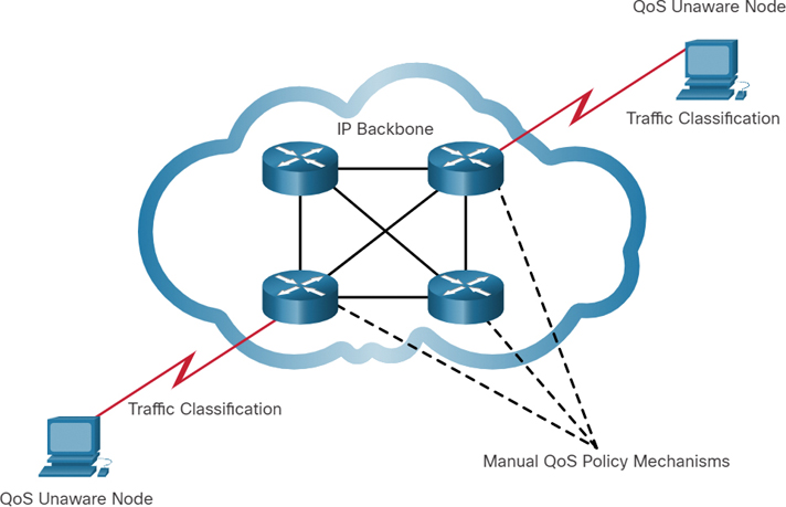
Figure 9-12 Simple DiffServ Example
As a host forwards traffic to a router, the router classifies the flows into aggregates (classes) and provides the appropriate QoS policy for the classes. DiffServ enforces and applies QoS mechanisms on a hop-by-hop basis, uniformly applying global meaning to each traffic class to provide both flexibility and scalability. For example, DiffServ could be configured to group all TCP flows as a single class and allocate bandwidth for that class rather than for the individual flows, as IntServ would do. In addition to classifying traffic, DiffServ minimizes signaling and state maintenance requirements on each network node.
Specifically, DiffServ divides network traffic into classes based on business requirements. Each of the classes can then be assigned a different level of service. As the packets traverse a network, each of the network devices identifies the packet class and services the packet according to that class. It is possible to choose many levels of service with DiffServ. For example, voice traffic from IP phones is usually given preferential treatment over all other application traffic, email is generally given best-effort service, and nonbusiness traffic can either be given very poor service or blocked entirely.
Table 9-9 lists the benefits and drawbacks of the DiffServ model.
Note
Modern networks primarily use the DiffServ model. However, due to the increasing volumes of delay- and jitter-sensitive traffic, IntServ and RSVP are sometimes co-deployed.
Table 9-9 Benefits and Drawbacks of the DiffServ Model
Benefits |
Drawbacks |
|
|
Check Your Understanding—QoS Models (9.4.6)
Refer to the online course to complete this activity.
QoS Implementation Techniques (9.5)
In this section, you’ll learn about the QoS mechanisms used to ensure transmission quality.
Video Tutorial—QoS Implementation Techniques (9.5.1)
Refer to the online course to view this video.
Avoiding Packet Loss (9.5.2)
Now that you have learned about traffic characteristics, queuing algorithms, and QoS models, it is time to learn about QoS implementation techniques.
Let’s start with packet loss. Packet loss is usually the result of congestion on an interface. Most applications that use TCP experience slowdown because TCP automatically adjusts to network congestion. Dropped TCP segments cause TCP sessions to reduce their window sizes. Some applications do not use TCP and cannot handle drops (fragile flows).
The following approaches can prevent drops in sensitive applications:
Increase link capacity to ease or prevent congestion.
Guarantee enough bandwidth and increase buffer space to accommodate bursts of traffic from fragile flows. WFQ, CBWFQ, and LLQ can guarantee bandwidth and provide prioritized forwarding to drop-sensitive applications.
Drop lower-priority packets before congestion occurs. Cisco IOS QoS provides queuing mechanisms, such as weighted random early detection (WRED), that start dropping lower-priority packets before congestion occurs.
QoS Tools (9.5.3)
There are three categories of QoS tools, as described in Table 9-10.
Table 9-10 Tools for Implementing QoS
QoS Tools |
Description |
Classification and marking tools |
|
Congestion avoidance tools |
|
Congestion management tools |
|
Refer to Figure 9-13 to better understand the sequence of how these tools are used when QoS is applied to packet flows.
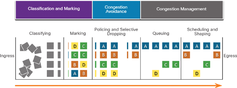
Figure 9-13 QoS Sequence
As shown in the figure, ingress packets (gray squares) are classified, and their respective IP header is marked (lettered squares). To avoid congestion, packets are then allocated resources based on defined policies. Packets are then queued and forwarded out the egress interface, based on their defined QoS shaping and policing policy.
Note
Classification and marking can be done on ingress or egress, whereas other QoS actions, such queuing and shaping, are usually done on egress.
Classification and Marking (9.5.4)
Before a packet can have a QoS policy applied to it, the packet has to be classified. Classification and marking allow you to identify or “mark” types of packets. Classification determines the class of traffic to which packets or frames belong. Only after traffic is marked can policies be applied to it.
How a packet is classified depends on the QoS implementation. Methods of classifying traffic flows at Layers 2 and 3 include using interfaces, ACLs, and class maps. Traffic can also be classified at Layers 4 to 7 using Network Based Application Recognition (NBAR).
Note
NBAR is a classification and protocol discovery feature of Cisco IOS software that works with QoS features. NBAR is beyond the scope of this chapter.
Marking involves adding a value to the packet header. Devices receiving the packet look at the marked field to see if it matches a defined policy. Marking should be done as close to the source device as possible to establish the trust boundary.
How traffic is marked usually depends on the technology. Table 9-11 lists some of the marking fields used in various technologies.
Table 9-11 Traffic Marking for QoS
QoS Tool |
Layer |
Marking Field |
Width, in Bits |
Ethernet (802.1Q, 802.1p) |
2 |
3 |
|
802.11 (Wi-Fi) |
2 |
Wi-Fi Traffic Identifier (TID) |
3 |
MPLS |
2 |
Experimental (EXP) |
3 |
IPv4 and IPv6 |
3 |
3 |
|
IPv4 and IPv6 |
3 |
6 |
The decision of whether to mark traffic at Layer 2 or Layer 3 (or both) is not trivial and should be made after consideration of the following points:
Layer 2 marking of frames can be performed for non-IP traffic.
Layer 2 marking of frames is the only QoS option available for switches that are not IP aware.
Layer 3 marking carries the QoS information from end to end.
Marking at Layer 2 (9.5.5)
802.1Q is the IEEE standard that supports VLAN tagging at Layer 2 on Ethernet networks. When 802.1Q is implemented, two fields are added to the Ethernet frame. As shown in Figure 9-14, these two fields are inserted into the Ethernet frame following the source MAC address field.
The 802.1Q standard also includes the QoS prioritization scheme known as IEEE 802.1p. The 802.1p standard uses the first 3 bits in the Tag Control Information (TCI) field. Known as the Priority (PRI) field, this 3-bit field identifies the Class of Service (CoS) markings. Three bits means that a Layer 2 Ethernet frame can be marked with one of eight levels of priority (values 0 through 7), as shown in Table 9-12.
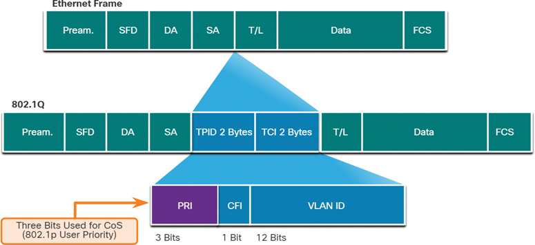
Figure 9-14 Ethernet Class of Service (CoS) Values
Table 9-12 Ethernet Class of Service (CoS) Values
CoS Value |
CoS Binary Value |
Description |
0 |
000 |
Best-effort data |
1 |
001 |
Medium-priority data |
2 |
010 |
High-priority data |
3 |
011 |
Call signaling |
4 |
100 |
Videoconferencing |
5 |
101 |
Voice bearer (voice traffic) |
6 |
110 |
Reserved |
7 |
111 |
Reserved |
Marking at Layer 3 (9.5.6)
IPv4 and IPv6 specify an 8-bit field in their packet headers to mark packets. As shown in Figure 9-15, both IPv4 and IPv6 support an 8-bit field for marking: the Type of Service (ToS) field for IPv4 and the Traffic Class field for IPv6.
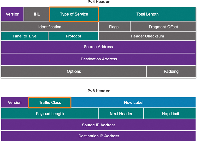
Figure 9-15 IPv4 and IPv6 Packet Headers
Type of Service and Traffic Class Field (9.5.7)
The Type of Service (IPv4) and Traffic Class (IPv6) fields carry the packet marking, as assigned by the QoS classification tools. The field is then referred to by receiving devices, which forward the packets based on the appropriate assigned QoS policy.
Figure 9-16 shows the contents of the 8-bit field. In RFC 791, the original IP standard specified the IP Precedence (IPP) field to be used for QoS markings. However, in practice, these 3 bits did not provide enough granularity to implement QoS.
RFC 2474 supersedes RFC 791 and redefines the ToS field by renaming and extending the IPP field. The new field, as shown in the figure, has 6 bits allocated for QoS and is called the Differentiated Services Code Point (DSCP) field. These 6 bits offer a maximum of 64 possible classes of service. The remaining 2 IP Extended Congestion Notification (ECN) bits can be used by ECN-aware routers to mark packets instead of dropping them. The ECN marking informs downstream routers that there is congestion in the packet flow.
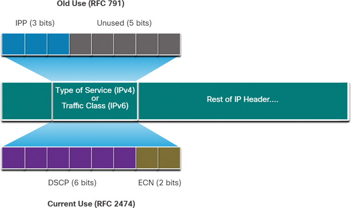
Figure 9-16 Type of Service and Traffic Class Fields in the Packet Header
DSCP Values (9.5.8)
The 64 DSCP values are organized into three categories:
Best Effort (BE): This is the default for all IP packets. The DSCP value is 0. The per-hop behavior is normal routing. When a router experiences congestion, these packets are dropped. No QoS plan is implemented.
Expedited Forwarding (EF): RFC 3246 defines EF as the DSCP decimal value 46 (binary 101110). The first 3 bits (101) map directly to the Layer 2 CoS value 5 used for voice traffic. At Layer 3, Cisco recommends that EF only be used to mark voice packets.
Assured Forwarding (AF): RFC 2597 defines AF to use the 5 most significant DSCP bits to indicate queues and drop preference. The definition of AF is illustrated in Figure 9-17.
The AFxy formula is specified as follows:
The first 3 most significant bits are used to designate the class. Class 4 is the best queue, and Class 1 is the worst queue.
The fourth and fifth most significant bits are used to designate the drop preference.
The sixth most significant bit is set to 0.
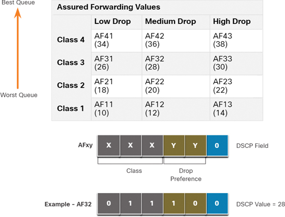
Figure 9-17 Assured Forwarding Values
For example, AF32 belongs to class 3 (binary 011) and has a medium drop preference (binary 10). The full DSCP value is 28 because you include the sixth 0 bit (binary 011100).
Class Selector Bits (9.5.9)
Because the first 3 most significant bits of the DSCP field indicate the class, these bits are also called the Class Selector (CS) bits. These 3 bits map directly to the 3 bits of the CoS field and the IPP field to maintain compatibility with 802.1p and RFC 791, as shown in Figure 9-18.
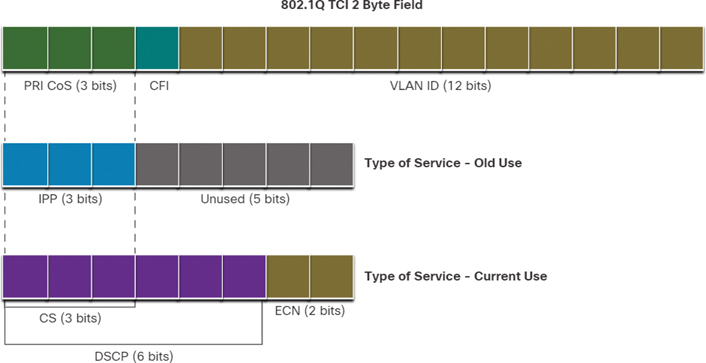
Figure 9-18 Layer 2 CoS and Layer 3 ToS
The table in Figure 9-19 shows how the CoS values map to the Class Selector bits and the corresponding DSCP 6-bit value. This same table can be used to map IPP values to the Class Selector bits.
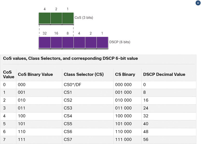
Figure 9-19 Mapping CoS to Class Selectors in DSCP
Trust Boundaries (9.5.10)
Where should markings occur? Traffic should be classified and marked as close to its source as technically and administratively feasible to define the trust boundary, as shown in Figure 9-20.
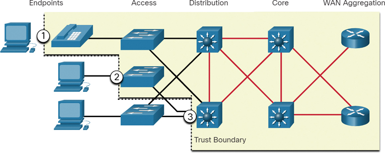
Figure 9-20 Various Trust Boundaries
The numbers in Figure 9-20 correspond to the following:
Trusted endpoints have the capabilities and intelligence to mark application traffic to the appropriate Layer 2 CoS and/or Layer 3 DSCP values. Examples of trusted endpoints include IP phones, wireless access points, videoconferencing gateways and systems, and IP conferencing stations.
Secure endpoints can have traffic marked at the Layer 2 switch.
Traffic can also be marked at Layer 3 switches / routers.
Re-marking traffic—for example, re-marking CoS values to IP Precedent or DSCP values—is typically necessary.
Congestion Avoidance (9.5.11)
Congestion management includes queuing and scheduling methods where excess traffic is buffered or queued (and sometimes dropped) while it waits to be sent out an egress interface. Congestion avoidance tools are simpler. They monitor network traffic loads in an effort to anticipate and avoid congestion at common network and internetwork bottlenecks before congestion becomes a problem. These tools can monitor the average depth of the queue, as represented in Figure 9-21. When the queue is below the minimum threshold, there are no drops. As the queue fills up to the maximum threshold, a small percentage of packets are dropped. When the maximum threshold is passed, all packets are dropped.
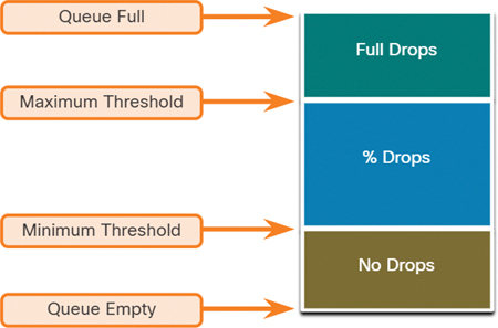
Figure 9-21 Congestion Avoidance Mechanisms
Some congestion avoidance techniques provide preferential treatment in terms of which packets will get dropped. For example, Cisco IOS QoS includes weighted random early detection (WRED) as a possible congestion avoidance solution. The WRED algorithm allows for congestion avoidance on network interfaces by providing buffer management and allowing TCP traffic to decrease, or throttle back, before buffers are exhausted. Using WRED helps avoid tail drops and maximizes network use and TCP-based application performance. There is no congestion avoidance for User Datagram Protocol (UDP)-based traffic, such as voice traffic. In case of UDP-based traffic, methods such as queuing and compression techniques help reduce and even prevent UDP packet loss.
Shaping and Policing (9.5.12)
Traffic shaping and traffic policing are two mechanisms provided by Cisco IOS QoS software to prevent congestion.
Traffic shaping retains excess packets in a queue and then schedules the excess for later transmission over increments of time. The result of traffic shaping is a smoothed packet output rate, as shown in Figure 9-22.
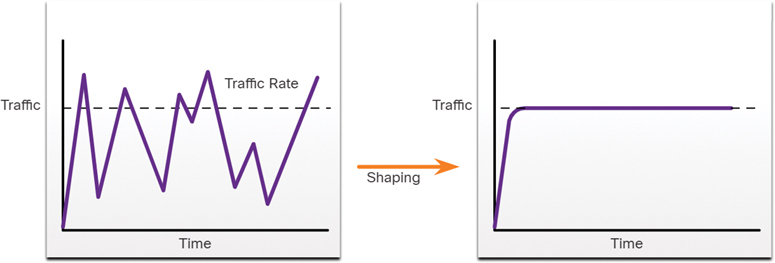
Figure 9-22 Traffic Shaping Example
Shaping implies the existence of a queue and of sufficient memory to buffer delayed packets, whereas policing does not.
Ensure that you have sufficient memory when enabling shaping. In addition, shaping requires a scheduling function for later transmission of any delayed packets. This scheduling function allows you to organize the shaping queue into different queues. Examples of scheduling functions are CBWFQ and LLQ.
Shaping is an outbound concept; packets going out an interface get queued and can be shaped. In contrast, policing is applied to inbound traffic on an interface. When the traffic rate reaches the configured maximum rate, excess traffic is dropped (or re-marked).
Policing is commonly implemented by service providers to enforce a contracted committed information rate (CIR), as shown in Figure 9-23. However, the service provider may also allow bursting over the CIR if the service provider’s network is not currently experiencing congestion.
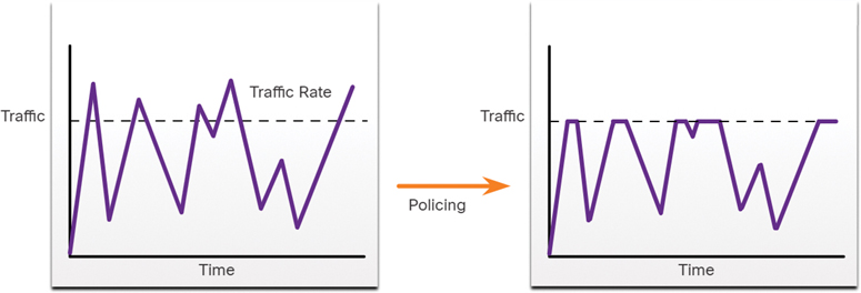
Figure 9-23 Traffic Policing Example
QoS Policy Guidelines (9.5.13)
A QoS policy must consider the full path from source to destination. If one device in the path is using a different policy than desired, then the entire QoS policy is impacted. For example, stutter in video playback could be the result of one switch in the path not having the CoS value set appropriately.
A few guidelines that help ensure the best experience for end users include the following:
Enable queuing at every device in the path between the source and the destination.
Classify and mark traffic as close to the source as possible.
Shape and police traffic flows as close to their sources as possible.
Check Your Understanding—QoS Implementation Techniques (9.5.14)
Refer to the online course to complete this activity.
Summary (9.6)
The following is a summary of the sections in this chapter.
Network Transmission Quality
Voice and live video transmissions create higher expectations for quality delivery among users and create a need for quality of service (QoS). Congestion occurs when multiple communication lines aggregate onto a single device, such as a router, and then much of that data is placed on just a few outbound interfaces or onto a slower interface. Congestion can also occur when large data packets prevent smaller packets from being transmitted in a timely manner. Without any QoS mechanisms in place, packets are processed in the order in which they are received. When congestion occurs, network devices such as routers and switches can drop packets. This means that time-sensitive packets, such as real-time video and voice, will be dropped with the same frequency as data that is not time sensitive, such as email and web browsing traffic. When the volume of traffic is greater than what can be transported across the network, devices queue (hold) the packets in memory until resources become available to transmit them. Queuing packets causes delay because new packets cannot be transmitted until previous packets have been processed. One QoS technique that can help with this problem is to classify data into multiple queues. Network congestion points are ideal candidates for QoS mechanisms to mitigate delay and latency. Two types of delays are fixed and variable. Sources of delay are code delay, packetization delay, queuing delay, serialization delay, propagation delay, and de-jitter delay. Jitter is the variation in the delay of received packets. Due to network congestion, improper queuing, or configuration errors, the delay between packets can vary instead of remaining constant. Both delay and jitter need to be controlled and minimized to support real-time and interactive traffic.
Traffic Characteristics
Voice and video traffic are two of the main reasons for QoS. Voice traffic is smooth and benign, but it is sensitive to drops and delays. Voice can tolerate a certain amount of latency, jitter, and loss without any noticeable effects. Latency should be no more than 150 milliseconds (ms). Jitter should be no more than 30 ms, and voice packet loss should be no more than 1%. Voice traffic requires at least 30 kbps of bandwidth. Video traffic is more demanding than voice traffic because of the size of the packets it sends across the network. Video traffic is bursty, greedy, drop sensitive, and delay sensitive. Without QoS and a significant amount of extra bandwidth, video quality typically degrades. UDP ports such as 554 are used for the Real-Time Streaming Protocol (RSTP) and should be given priority over other, less delay-sensitive, network traffic. Similar to voice, video can tolerate a certain amount of latency, jitter, and loss without any noticeable effects. Latency should be no more than 400 milliseconds (ms). Jitter should be no more than 50 ms, and video packet loss should be no more than 1%. Video traffic requires at least 384 kbps of bandwidth. Data traffic is not as demanding as voice and video traffic. Data packets often use TCP applications, which can retransmit data and, therefore, are not sensitive to drops and delays. Although data traffic is relatively insensitive to drops and delays compared to voice and video, a network administrator still needs to consider the quality of the user experience, sometimes referred to as quality of experience (QoE). The two main factors that a network administrator needs to consider about the flow of data traffic are whether the data comes from an interactive application and whether the data is mission critical.
Queuing Algorithms
The QoS policy implemented by a network administrator becomes active when congestion occurs on the link. Queuing is a congestion management tool that can buffer, prioritize, and, if required, reorder packets before being transmitted to the destination. This chapter focuses on the following queuing algorithms: first-in, first-out (FIFO), Weighted Fair Queuing (WFQ), Class-Based Weighted Fair Queuing (CBWFQ), and Low Latency Queuing (LLQ). FIFO queuing buffers and forwards packets in the order of their arrival. FIFO has no concept of priority or classes of traffic and, consequently, makes no decision about packet priority. When FIFO is used, important or time-sensitive traffic can be dropped when there is congestion on the router or switch interface. WFQ is an automated scheduling method that provides fair bandwidth allocation to all network traffic. WFQ applies priority, or weights, to identified traffic and classifies it into conversations or flows. WFQ classifies traffic into different flows based on packet header addressing, including such characteristics as source and destination IP addresses, MAC addresses, port numbers, protocol, and Type of Service (ToS) value. The ToS value in the IP header can be used to classify traffic. CBWFQ extends the standard WFQ functionality to provide support for user-defined traffic classes. With CBWFQ, you define traffic classes based on match criteria including protocols, access control lists (ACLs), and input interfaces. The LLQ feature brings strict priority queuing (PQ) to CBWFQ. Strict PQ allows delay-sensitive packets, such as voice, to be sent before packets in other queues, reducing jitter in voice conversations.
QoS Models
There are three models for implementing QoS: best-effort model, Integrated Services (IntServ), and Differentiated Services (DiffServ). The best-effort model is the most scalable but does not guarantee delivery and does not give any packets preferential treatment. The IntServ model was developed to meet the needs of real-time applications, such as remote video, multimedia conferencing, data visualization applications, and virtual reality. IntServ is a multiple-service model that can accommodate many QoS requirements. IntServ explicitly manages network resources to provide QoS to individual flows or streams, sometimes called microflows. It uses resource reservation and admission-control mechanisms as building blocks to establish and maintain QoS. The DiffServ QoS model specifies a simple and scalable mechanism for classifying and managing network traffic. The DiffServ design overcomes the limitations of both the best-effort and IntServ models. The DiffServ model can provide an “almost guaranteed” QoS while still being cost-effective and scalable. DiffServ divides network traffic into classes based on business requirements. Each of the classes can then be assigned a different level of service. As the packets traverse a network, each of the network devices identifies the packet class and services the packet according to that class. It is possible to choose many levels of service with DiffServ.
QoS Implementation Techniques
There are three categories of QoS tools: classification and marking tools, congestion avoidance tools, and congestion management tools. Before a packet can have a QoS policy applied to it, the packet has to be classified. Classification and marking enable you to identify, or “mark,” types of packets. Classification determines the class of traffic to which packets or frames belong. Methods of classifying traffic flows at Layers 2 and 3 include using interfaces, ACLs, and class maps. Traffic can also be classified at Layers 4 to 7 using Network Based Application Recognition (NBAR). The Type of Service (IPv4) and Traffic Class (IPv6) fields carry the packet marking as assigned by the QoS classification tools. The field is then referred to by receiving devices, which forward the packets based on the appropriate assigned QoS policy. These fields have 6 bits allocated for QoS. Called the Differentiated Services Code Point (DSCP) field, these 6 bits offer a maximum of 64 possible classes of service. The field is then referred to by receiving devices, which forward the packets based on the appropriate assigned QoS policy. The 64 DSCP values are organized into three categories: Best Effort (BE), Expedited Forwarding (EF), and Assured Forwarding (AF). Because the first 3 most significant bits of the DSCP field indicate the class, these bits are also called the Class Selector (CS) bits. Traffic should be classified and marked as close to its source as technically and administratively feasible to define the trust boundary. Congestion management includes queuing and scheduling methods where excess traffic is buffered or queued (and sometimes dropped) while it waits to be sent out an egress interface. Congestion avoidance tools help to monitor network traffic loads in an effort to anticipate and avoid congestion at common network and internetwork bottlenecks before congestion becomes a problem. Cisco IOS QoS includes weighted random early detection (WRED) as a possible congestion avoidance solution. The WRED algorithm allows for congestion avoidance on network interfaces by providing buffer management and allowing TCP traffic to decrease, or throttle back, before buffers are exhausted. Traffic shaping and traffic policing are two mechanisms provided by Cisco IOS QoS software to prevent congestion.
Practice
There are no labs or Packet Tracers for this chapter.
Check Your Understanding Questions
Complete all the review questions listed here to test your understanding of the topics and concepts in this chapter. The appendix “Answers to the ‘Check Your Understanding’ Questions” lists the answers.
1. Under which condition does congestion occur on a converged network with voice, video, and data traffic?
A user downloads a file that exceeds the file limitation that is set on the server.
A request for bandwidth exceeds the amount of bandwidth available.
Video traffic requests more bandwidth than voice traffic requests.
Voice traffic latency begins to decrease across the network.
2. What functionality is required on routers to provide remote workers with VoIP and video-conferencing capabilities?
IPsec
PPPoE
QoS
VPN
3. What happens when a router interface ingress queue is full and new network traffic is received?
The router sends the received traffic immediately.
The router drops the arriving packets.
The router drops all traffic in the queue.
The router queues the received traffic and sends previously received traffic.
4. Which queuing method provides user-defined traffic classes where each traffic class has a FIFO queue?
CBWFQ
RSVP
WFQ
WRED
5. Which type of traffic does Cisco recommend be placed in the strict priority queue when Low Latency Queuing (LLQ) is being used?
Data
Management
Video
Voice
6. What is the default queuing method used on the LAN interfaces of Cisco devices?
CBWFQ
FIFO
LLQ
WFQ
7. What is the default queuing method used on the slower WAN interfaces of Cisco devices?
CBWFQ
FIFO
LLQ
WFQ
8. Which model is the only QoS model with no mechanism to classify packets?
Best-effort
DiffServ
Hard QoS
IntServ
9. What happens when an edge router using IntServ QoS determines that the data pathway cannot support the level of QoS requested?
Data is forwarded along the pathway using a best-effort approach.
Data is forwarded along the pathway using DiffServ.
Data is not forwarded along the pathway.
Data is forwarded along the pathway using IntServ but is not provided preferential treatment.
10. Which statement describes the QoS classification and marking tools?
Classification is performed after traffic is marked.
Classification should be done as close to the destination service as possible.
Marking involves adding a value to a packet header.
Marking involves identification of the QoS policy that should be applied to specific packets.
11. Which device would be classified as a trusted endpoint?
Firewall
IP conferencing station
Router
Switch
12. How many bits are used to identify the Class of Service (CoS) marking in a frame?
3
8
24
64
13. How many levels of priority are possible when using Class of Service (CoS) marking on frames?
3
8
24
64