Chapter 13
Network Virtualization
Objectives
Upon completion of this chapter, you will be able to answer the following questions:
What is the importance of cloud computing?
What is the importance of virtualization?
What is virtualization of network devices and services?
What is software-defined networking?
What controllers are used in network programming?
Key Terms
This chapter uses the following key terms. You can find the definitions in the Glossary.
network virtualization page 583
National Institute of Standards and Technology (NIST) page 584
software as a service (SaaS) page 584
platform as a service (PaaS) page 584
infrastructure as a service (IaaS) page 584
IT as a service (ITaaS) page 584
Amazon Web Services (AWS) page 586
Internet of Things (IoT) page 586
Cisco Unified Computing System (UCS) page 593
virtual routing and forwarding (VRF) page 595
software-defined networking (SDN) page 595
Cisco Express Forwarding (CEF) page 596
Forwarding Information Base (FIB) page 596
Cisco Application Centric Infrastructure (ACI) page 598
application programming interface (API) page 599
Application Network Profile (ANP) page 602
Application Policy Infrastructure Controller (APIC) page 602
Cisco Nexus 9000 Series switch page 602
Cisco Application Policy Infrastructure Controller—Enterprise Module (APIC-EM) page 604
Introduction (13.0)
Imagine that you live in a two-bedroom house. You use the second bedroom for storage. The second bedroom is packed full of boxes, but you still have more to place in storage! You could consider building an addition on your house. It would be a costly endeavor, and you might not need that extra space forever. You decide to rent a storage unit for the overflow.
Similar to a storage unit, network virtualization and cloud services can provide a business with options other than adding servers into their own data center. In addition to storage, virtualization offers other advantages. Get started with this chapter to learn more about what virtualization and cloud services can do!
Cloud Computing (13.1)
In this section, you will learn the importance of cloud computing.
Video—Cloud and Virtualization (13.1.1)

Refer to the online course to view this video.
Cloud Overview (13.1.2)
Cloud computing involves large numbers of computers connected through a network that can be physically located anywhere. Providers rely heavily on virtualization to deliver their cloud computing services. Cloud computing can reduce operational costs by using resources more efficiently. Cloud computing addresses a variety of data management issues by doing the following:
Enabling access to organizational data anywhere and at any time
Streamlining the organization’s IT operations by allowing the organization to subscribe only to needed services
Eliminating or reducing the need for onsite IT equipment, maintenance, and management
Reducing costs for equipment, energy, physical plant requirements, and personnel training needs
Enabling rapid responses to increasing data volume requirements
Cloud computing, with its “pay-as-you-go” model, allows organizations to treat computing and storage expenses as a utility rather than investing in infrastructure. It enables an organization to transform capital expenditures into operating expenditures.
Cloud Services (13.1.3)
Cloud services are available in a variety of options, tailored to meet customer requirements. The three main cloud computing services defined by the National Institute of Standards and Technology (NIST) in Special Publication 800-145 are as follows:
Software as a service (SaaS): The cloud provider is responsible for access to applications and services (such as email, communication, and Office 365) that are delivered over the internet. The user does not manage any aspect of the cloud services except for limited user-specific application settings. The user only needs to provide the data.
Platform as a service (PaaS): The cloud provider is responsible for providing users access to the development tools and services used to deliver the applications. These users are typically programmers and may have control over the configuration settings of the cloud provider’s application-hosting environment.
Infrastructure as a service (IaaS): The cloud provider is responsible for giving IT managers access to network equipment, virtualized network services, and supporting network infrastructure. Using this cloud service allows IT managers to deploy and run software code, which can include operating systems and applications.
Cloud service providers have extended this model to also provide IT support for each of the cloud computing services. For businesses, IT as a service (ITaaS) can extend the capability of the network without requiring investment in new infrastructure, training of new personnel, or licensing of new software. These services are available on demand and delivered economically to any device anywhere in the world, without compromising security or function.
Cloud Models (13.1.4)
There are four primary cloud models.
Public cloud: Cloud-based applications and services offered in a public cloud are made available to the general population. Services may be free or are offered on a pay-per-use model, such as paying for online storage. A public cloud uses the internet to provide services.
Private cloud: Cloud-based applications and services offered in a private cloud are intended for a specific organization or entity, such as the government. A private cloud can be set up using the organization’s private network, although this can be expensive to build and maintain. A private cloud can also be managed by an outside organization with strict access security.
Hybrid cloud: A hybrid cloud is made up of two or more clouds (for example, part private and part public), where each part remains a separate object but the two are connected using a single architecture. Individuals on a hybrid cloud would be able to have degrees of access to various services, based on user access rights.
Community cloud: A community cloud is created for exclusive use by a specific community. The differences between public clouds and community clouds are the functional needs that have been customized for the community. For example, healthcare organizations must remain compliant with policies and laws (such as HIPAA) that require special authentication and confidentiality.
Cloud Computing Versus Data Center (13.1.5)
The terms data center and cloud computing are often used incorrectly. These are the correct definitions of the two terms:
Data center: Typically, a data storage and processing facility run by an in-house IT department or leased offsite.
Cloud computing: Typically, an off-premises service that offers on-demand access to a shared pool of configurable computing resources. These resources can be rapidly provisioned and released with minimal management effort.
Data centers are physical facilities that provide the compute, network, and storage needs of cloud computing services. Cloud service providers use data centers to host their cloud services and cloud-based resources.
A data center can occupy one room of a building, one or more floors, or an entire building. Data centers are typically very expensive to build and maintain. For this reason, only large organizations use privately built data centers to house their data and provide services to users. Smaller organizations that cannot afford to maintain their own private data centers can reduce the overall cost of ownership by leasing cloud-based server and storage services from a larger data center organization.
Check Your Understanding—Cloud Computing (13.1.6)

Refer to the online course to complete this activity.
Virtualization (13.2)
In this section, you will learn the importance of virtualization.
Cloud Computing and Virtualization (13.2.1)
In the previous section, you learned about cloud services and cloud models. This section explains virtualization. The terms cloud computing and virtualization are often used interchangeably; however, they mean different things. Virtualization is the foundation of cloud computing. Without it, cloud computing, as it is most widely implemented, would not be possible.
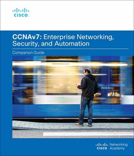
Virtualization separates the operating system (OS) from the hardware. Various providers offer virtual cloud services that can dynamically provision servers as required. For example, Amazon Web Services (AWS) provides a simple way for customers to dynamically provision the compute resources needed. These virtualized instances of servers are created on demand. As shown in Figure 13-1, a network administrator can deploy a variety of services from the AWS Management Console, including virtual machines (VMs), web applications, virtual servers, and connections to Internet of Things (IoT) devices.
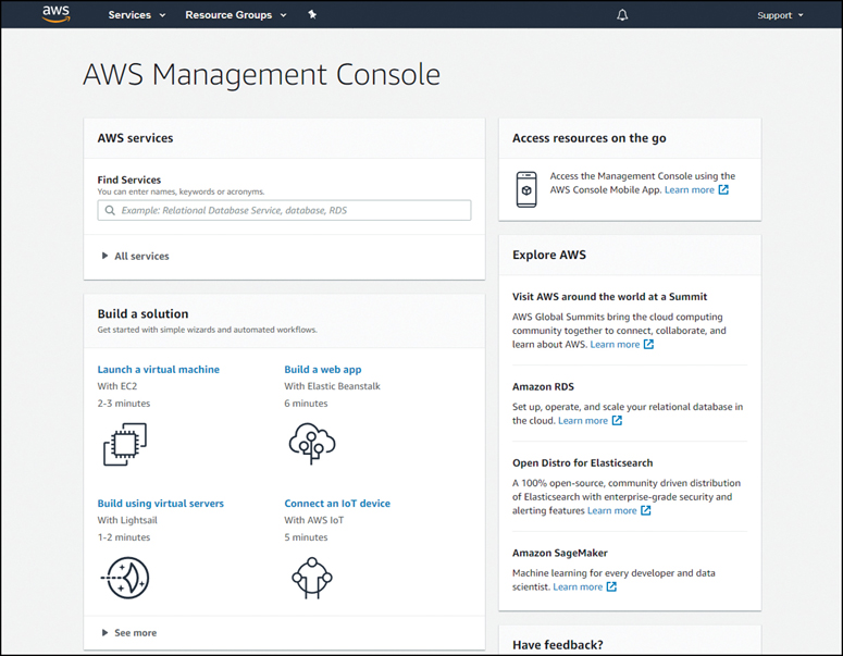
Figure 13-1 AWS Management Console
Dedicated Servers (13.2.2)
To fully appreciate virtualization, it is necessary to understand some of the history of server technology. Historically, enterprise servers consisted of a server OS, such as Windows Server or Linux Server, installed on specific hardware, as shown in Figure 13-2.
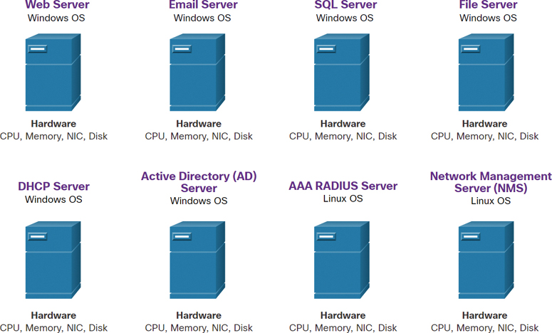
Figure 13-2 Examples of Dedicated Servers
All of a server’s RAM, processing power, and hard drive space were dedicated to the service provided (for example, web services, email services). The major problem with such a configuration is that when a component fails, the service that is provided by this server becomes unavailable. This is known as a single point of failure. Another problem is that dedicated servers can be underused. Dedicated servers often sit idle for long periods of time, waiting until there is a need to deliver the specific service they provide. These servers waste energy and take up more space than is warranted by the service provided. This is known as server sprawl.
Server Virtualization (13.2.3)
Server virtualization takes advantage of idle resources and consolidates the number of required servers. This also allows for multiple operating systems to exist on a single hardware platform.
For example, in Figure 13-3, the eight dedicated servers shown in Figure 13-2 have been consolidated into two servers by using hypervisors to support multiple virtual instances of the operating systems.
Figure 13-3 Examples of Server Virtualization
The use of virtualization normally includes redundancy to prevent single points of failure. Redundancy can be implemented in different ways. If the hypervisor fails, the VM can be restarted on another hypervisor. Also, the same VM can run on two hypervisors concurrently, copying the RAM and CPU instructions between them. If one hypervisor fails, the VM continues running on the other hypervisor. The services running on the VMs are also virtual and can be dynamically installed or uninstalled, as needed.
The hypervisor is a program, firmware, or hardware that adds an abstraction layer on top of the physical hardware. The abstraction layer is used to create virtual machines that have access to all the hardware of the physical machine, such as CPUs, memory, disk controllers, and NICs. Each of these virtual machines runs a complete and separate operating system. With virtualization, enterprises can now consolidate the number of servers required. For example, it is not uncommon for 100 physical servers to be consolidated as virtual machines on top of 10 physical servers that are using hypervisors.
Advantages of Virtualization (13.2.4)
One major advantage of virtualization is overall reduced cost, thanks to several factors:
Less equipment is required: Virtualization enables server consolidation, requiring fewer physical servers, fewer networking devices, and less supporting infrastructure. It also means lower maintenance costs.
Less energy is consumed: Consolidating servers lowers the monthly power and cooling costs. Reduced consumption helps enterprises achieve a smaller carbon footprint.
Less space is required: Server consolidation with virtualization reduces the overall footprint of a data center. Fewer servers, network devices, and racks reduce the amount of floor space required.
These are additional benefits of virtualization:
Easier prototyping: Self-contained labs, operating on isolated networks, can be rapidly created for testing and prototyping network deployments. If a mistake is made, an administrator can simply revert to a previous version. The testing environments can be online but isolated from end users. When testing is complete, the servers and systems can be deployed to end users.
Faster server provisioning: Creating a virtual server is far faster than provisioning a physical server.
Increased server uptime: Most server virtualization platforms now offer advanced redundant fault-tolerance features, such as live migration, storage migration, high availability, and distributed resource scheduling.
Improved disaster recovery: Virtualization offers advanced business continuity solutions. It provides hardware abstraction capability so that the recovery site no longer needs to have hardware that is identical to the hardware in the production environment. Most enterprise server virtualization platforms also have software that can help test and automate the failover before a disaster does happen.
Legacy support: Virtualization can extend the life of OSs and applications, providing more time for organizations to migrate to newer solutions.
Abstraction Layers (13.2.5)
It is useful to use layers of abstraction in computer architectures to help explain how virtualization works. A computer system consists of the abstraction layers illustrated in Figure 13-4.
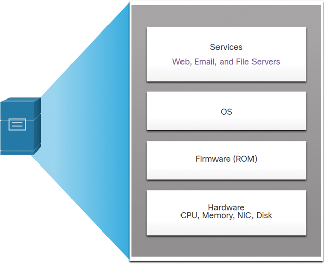
Figure 13-4 Computer Abstraction Layers
At each of these layers of abstraction, some type of programming code is used as an interface between the layer below and the layer above. For example, the C programming language is often used to program the firmware that accesses the hardware.
An example of virtualization is shown in Figure 13-5. A hypervisor is installed between the firmware and the OS. The hypervisor can support multiple instances of OSs.
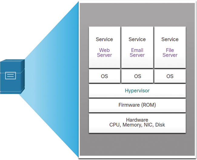
Figure 13-5 Computer with Multiple Virtualized OSs Installed
Type 2 Hypervisors (13.2.6)
A Type 2 hypervisor is software that creates and runs VM instances. The computer on which a hypervisor is supporting one or more VMs is a host machine. A Type 2 hypervisor is also called a hosted hypervisor because the hypervisor is installed on top of the existing host OS, such as macOS, Windows, or Linux. One or more additional guest OS instances are installed on top of the hypervisor, as shown in Figure 13-6.
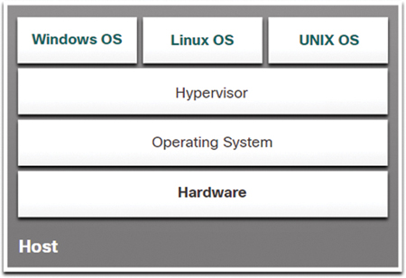
Figure 13-6 Example of a Type 2 Hypervisor
A big advantage of Type 2 hypervisors is that management console software is not required.
Type 2 hypervisors are very popular with consumers and with organizations experimenting with virtualization. Common Type 2 hypervisors include:
Virtual PC
VMware Workstation
Oracle VM VirtualBox
VMware Fusion
Mac OS X Parallels
Many of these Type 2 hypervisors are free. However, some hypervisors offer more advanced features for a fee.
Note
It is important to make sure that a host machine is robust enough to install and run the VMs and not run out of resources.
Check Your Understanding—Virtualization (13.2.7)
Refer to the online course to complete this activity.
Virtual Network Infrastructure (13.3)
In the previous section, you learned about virtualization. This section covers the virtual network infrastructure.
Type 1 Hypervisors (13.3.1)
Using Type 1 hypervisors is also called the “bare metal” approach because the hypervisor is installed directly on the hardware. Type 1 hypervisors are usually used on enterprise servers and data center networking devices.
A Type 1 hypervisor is installed directly on the server or networking hardware. Instances of an OS are installed on the hypervisor, as shown in Figure 13-7.
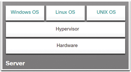
Figure 13-7 Example of a Type 1 Hypervisor
Type 1 hypervisors have direct access to the hardware resources. Therefore, they are more efficient than hosted architectures. Type 1 hypervisors improve scalability, performance, and robustness.
Installing a VM on a Hypervisor (13.3.2)
When a Type 1 hypervisor is installed and the server is rebooted, only basic information is displayed, such as the OS version, the amount of RAM, and the IP address. An OS instance cannot be created from this screen. Type 1 hypervisors require a “management console” to manage the hypervisor. Management software is used to manage multiple servers using the same hypervisor. The management console can automatically consolidate servers and power on or off servers as required.
For example, say that Server 1 in Figure 13-8 becomes low on resources.
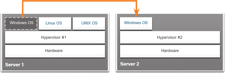
Figure 13-8 Moving a VM to Another Hardware Server
To make more resources available, the network administrator can use the management console to move the Windows instance to the hypervisor on Server 2. The management console can also be programmed with thresholds that can trigger the move automatically.
The management console enables recovery from hardware failure. If a server component fails, the management console automatically moves the VM to another server. The management console for the Cisco Unified Computing System (UCS) is shown in Figure 13-9. Cisco UCS Manager controls multiple servers and manages resources for thousands of VMs.
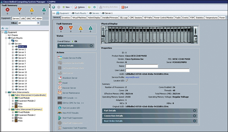
Figure 13-9 Cisco UCS Manager
Some management consoles allow server overallocation. With overallocation, multiple OS instances are installed, but their memory allocation exceeds the total amount of memory that a server has. For example, if a server has 16 GB of RAM, the administrator may create four OS instances with 10 GB of RAM allocated to each. This type of overallocation is a common practice because all four OS instances rarely require the full 10 GB of RAM at any one moment.
The Complexity of Network Virtualization (13.3.3)
Server virtualization hides from server users server resources such as the number and identity of physical servers, processors, and OSs. This practice can create problems if the data center is using traditional network architectures.
For example, virtual LANs (VLANs) used by VMs must be assigned to the same switchport as the physical server running the hypervisor. However, VMs are movable, and the network administrator must be able to add, drop, and change network resources and profiles. This process would be manual and time-consuming with traditional network switches.
Another problem is that traffic flows differ substantially from those in the traditional client/server model. Typically, a data center has a considerable amount of traffic being exchanged between virtual servers, such as the UCS servers shown in Figure 13-10.
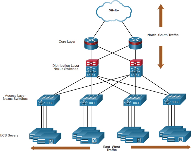
Figure 13-10 Example of North–South and East–West Traffic
These flows are called east–west traffic and can change in location and intensity over time. North–south traffic occurs between the distribution and core layers and is typically traffic destined for offsite locations such as another data center, other cloud providers, or the internet.
Dynamic ever-changing traffic requires a flexible approach to network resource management. Existing network infrastructures can respond to changing requirements related to the management of traffic flows by using quality of service (QoS) and security level configurations for individual flows. However, in large enterprises using multivendor equipment, each time a new VM is enabled, the necessary reconfiguration can be very time-consuming.
The network infrastructure can also benefit from virtualization. Network functions can be virtualized. Each network device can be segmented into multiple virtual devices that operate as independent devices. Examples include subinterfaces, virtual interfaces, VLANs, and routing tables. Virtualized routing is called virtual routing and forwarding (VRF).
How is the network virtualized? The answer is found in how a networking device operates using a data plane and a control plane, as discussed in the next section.
Check Your Understanding—Virtual Network Infrastructure (13.3.4)
Refer to the online course to complete this activity.
Software-Defined Networking (13.4)
The previous section explains virtual network infrastructure. This section covers software-defined networking (SDN).
Video—Software-Defined Networking (13.4.1)
Refer to the online course to view this video.
Control Plane and Data Plane (13.4.2)
A network device contains the following planes:
Control plane: This is typically regarded as the brains of a device. It is used to make forwarding decisions. The control plane contains Layer 2 and Layer 3 route forwarding mechanisms, such as routing protocol neighbor tables and topology tables, IPv4 and IPv6 routing tables, STP, and the ARP table. Information sent to the control plane is processed by the CPU.
Data plane: Also called the forwarding plane, this plane is typically the switch fabric connecting the various network ports on a device. The data plane of each device is used to forward traffic flows. Routers and switches use information from the control plane to forward incoming traffic out the appropriate egress interface. Information in the data plane is typically processed by a special data plane processor, without the CPU getting involved.
The following explains the differences between the operation of localized control on a Layer 3 switch and a centralized controller in SDN.
Layer 3 Switch and CEF
Figure 13-11 illustrates how Cisco Express Forwarding (CEF) uses the control plane and data plane to process packets.
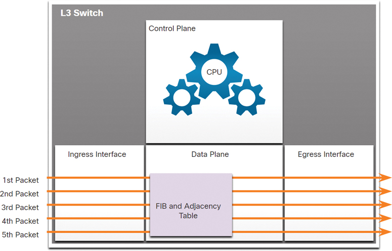
Figure 13-11 Illustration of Layer 3 Switch with CEF
CEF is an advanced Layer 3 IP switching technology that enables forwarding of packets to occur at the data plane without consulting the control plane. In CEF, the control plane’s routing table prepopulates the CEF Forwarding Information Base (FIB) table in the data plane. The control plane’s ARP table prepopulates the adjacency table. The data plane then forwards packets directly, based on the information contained in the FIB and adjacency table, without needing to consult the information in the control plane.
SDN and Central Controller
SDN basically involves the separation of the control plane and data plane. The control plane function is removed from each device and is performed by a centralized controller. The centralized controller communicates control plane functions to each device. Each device can then focus on forwarding data while the centralized controller manages data flow, increases security, and provides other services.
Figure 13-12 illustrates a centralized control plane communicating control plane functions to each device.
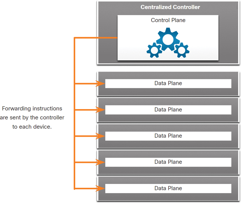
Figure 13-12 Illustration of SDN and Central Controller
At the top of the figure is the centralized control plane controller. There are arrows pointing from the control plane to five data planes. Forwarding instructions are sent by the controller to each device.
Management Plane
The management plane (which is not shown in the figures) is responsible for managing a device through its connection to the network. Network administrators use applications such as Secure Shell (SSH), Trivial File Transfer Protocol (TFTP), Secure FTP, and Secure Hypertext Transfer Protocol (HTTPS) to access the management plane and configure a device. In your networking studies, you have used the management plane to access and configure devices. In addition, protocols such as Simple Network Management Protocol (SNMP) use the management plane.
Network Virtualization Technologies (13.4.3)
Over a decade ago, VMware developed a virtualizing technology that enables a host OS to support one or more client OSs. Most virtualization technologies are now based on this technology. The transformation of dedicated servers to virtualized servers has been embraced and is rapidly being implemented in data center and enterprise networks.
Two major network architectures have been developed to support network virtualization:
Software-defined networking (SDN): A network architecture that virtualizes the network, offering a new approach to network administration and management that seeks to simplify and streamline the administration process.
Cisco Application Centric Infrastructure (ACI): A purpose-built hardware solution for integrating cloud computing and data center management.
Components of SDN may include the following:
OpenFlow: This approach was developed at Stanford University to manage traffic between routers, switches, wireless access points, and a controller. The OpenFlow protocol is a basic element in building SDN solutions. Search online for OpenFlow and the Open Networking Foundation for more information.
OpenStack: This approach is a virtualization and orchestration platform designed to build scalable cloud environments and provide an IaaS solution. OpenStack is often used with Cisco ACI. Orchestration in networking is the process of automating the provisioning of network components such as servers, storage, switches, routers, and applications. Search online for OpenStack for more information.
Other components: Other components include Interface to the Routing System (I2RS), Transparent Interconnection of Lots of Links (TRILL), Cisco FabricPath (FP), and IEEE 802.1aq Shortest Path Bridging (SPB).
Traditional and SDN Architectures (13.4.4)
In a traditional router or switch architecture, the control plane and data plane functions occur in the same device. Routing decisions and packet forwarding are the responsibility of the device operating system. In SDN, management of the control plane is moved to a centralized SDN controller. Figure 13-13 compares traditional and SDN architectures.
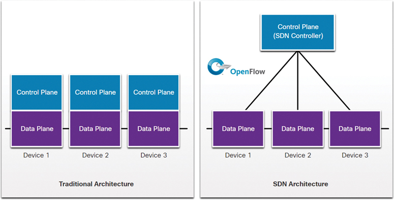
Figure 13-13 Traditional and SDN Architecture Comparison
An SDN controller is a logical entity that enables network administrators to manage and dictate how the data plane of switches and routers should handle network traffic. It orchestrates, mediates, and facilitates communication between applications and network elements.
The complete SDN framework is shown in Figure 13-14.
Note the use of application programming interfaces (APIs) in the SDN framework. An API is a set of standardized requests that define the proper way for an application to request services from another application.
An SDN controller uses northbound APIs to communicate with the upstream applications. These APIs help network administrators shape traffic and deploy services. An SDN controller also uses southbound APIs to define the behavior of the data planes on downstream switches and routers. OpenFlow is the original and widely implemented southbound API.
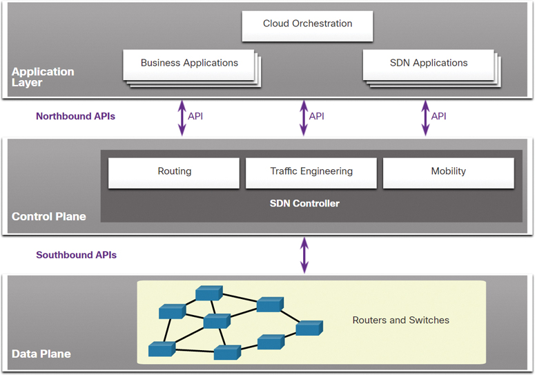
Figure 13-14 SDN Framework
Check Your Understanding—Software-Defined Networking (13.4.5)
Refer to the online course to complete this activity.
Controllers (13.5)
The previous section covers SDN. This section explains SDN controllers.
SDN Controller and Operations (13.5.1)
An SDN controller defines the data flows between the centralized control plane and the data planes on individual routers and switches.
Each flow traveling through a network must first get permission from the SDN controller, which verifies that the communication is permissible according to the network policy. If the controller allows a flow, it computes a route for the flow to take and adds an entry for that flow in each of the switches along the path.
All complex functions are performed by the controller. The controller populates flow tables. Switches manage the flow tables. In Figure 13-15, an SDN controller communicates with OpenFlow-compatible switches using the OpenFlow protocol.
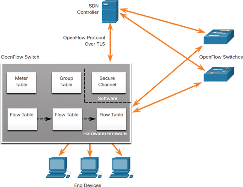
Figure 13-15 Example of SDN Controller Operations
OpenFlow uses Transport Layer Security (TLS) to securely send control plane communications over the network. Each OpenFlow switch connects to other OpenFlow switches. These switches can also connect to end-user devices that are part of a packet flow.
Within each switch, a series of tables implemented in hardware or firmware are used to manage the flows of packets through the switch. To the switch, a flow is a sequence of packets that matches a specific entry in a flow table.
Three tables types are shown in Figure 13-15:
Flow table: This table matches incoming packets to a particular flow and specifies the functions that are to be performed on the packets. There may be multiple flow tables operating in a pipeline fashion.
Group table: A flow table may direct a flow to a group table, which may trigger a variety of actions that affect one or more flows.
Meter table: This table triggers a variety of performance-related actions on a flow, including the ability to rate limit the traffic.
Video—Cisco ACI (13.5.2)
Very few organizations actually have the desire or skill to program a network using SDN tools. However, the majority of organizations want to automate their networks, accelerate application deployments, and align their IT infrastructures to better meet business requirements. Cisco developed the Application Centric Infrastructure (ACI) to meet these objectives in more advanced and innovative ways than earlier SDN approaches.
Cisco ACI is a hardware solution for integrating cloud computing and data center management. At a high level, the policy element of the network is removed from the data plane. This simplifies the way data center networks are created.
Refer to the online course to view this video.
Core Components of ACI (13.5.3)
These are the three core components of the ACI architecture:
Application Network Profile (ANP): An ANP is a collection of endpoint groups (EPG), their connections, and the policies that define those connections. The EPGs, such as VLANs, web services, and applications, are just examples. An ANP is often much more complex.
Application Policy Infrastructure Controller (APIC): The APIC is considered the brains of the ACI architecture. An APIC is a centralized software controller that manages and operates a scalable ACI clustered fabric. It is designed for programmability and centralized management. It translates application policies into network programming.
Cisco Nexus 9000 Series switches: These switches provide an application-aware switching fabric and work with an APIC to manage the virtual and physical network infrastructure.
An APIC is positioned between the APN and the ACI-enabled network infrastructure. The APIC translates the application requirements into a network configuration to meet those needs, as shown in Figure 13-16.
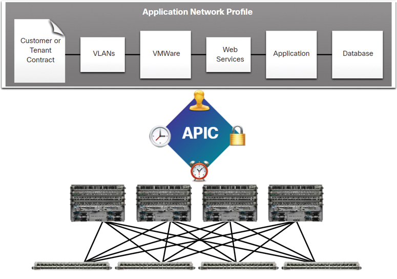
Figure 13-16 Example of APIC Operation
Spine-Leaf Topology (13.5.4)
The Cisco ACI fabric is composed of the APIC and the Cisco Nexus 9000 Series switches using two-tier spine-leaf topology, as shown in Figure 13-17.
The leaf switches always attach to the spines, but they never attach to each other. Similarly, the spine switches only attach to the leaf and core switches (not shown). In this two-tier topology, everything is one hop from everything else.
The Cisco APICs and all other devices in the network physically attach to leaf switches.
Unlike with SDN, the APIC controller does not manipulate the data path directly. Instead, the APIC centralizes the policy definition and programs the leaf switches to forward traffic based on the defined policies.
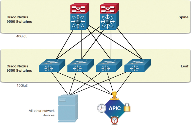
Figure 13-17 Example of a Spine-Leaf Topology
SDN Types (13.5.5)
The Cisco Application Policy Infrastructure Controller—Enterprise Module (APIC-EM) extends ACI aimed at enterprise and campus deployments. To better understand APIC-EM, it is helpful to take a broader look at the three types of SDN.
Device-Based SDN
In device-based SDN, the devices are programmable by applications running on the device itself or on a server in the network, as shown in Figure 13-18.
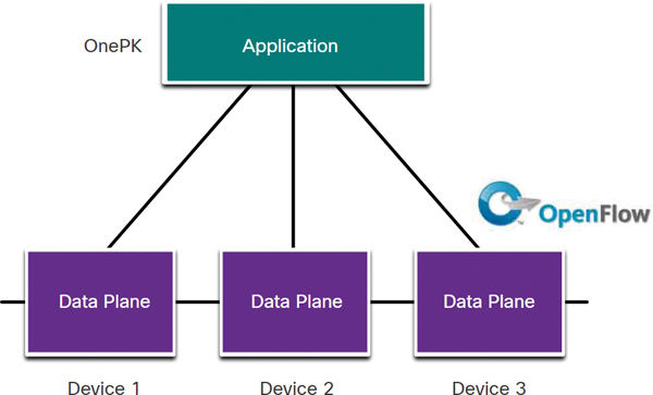
Figure 13-18 Device-Based SDN
Cisco OnePK is an example of a device-based SDN. It enables programmers to build applications using C and Java with Python to integrate and interact with Cisco devices.
Controller-Based SDN
A controller-based SDN uses a centralized controller that has knowledge of all devices in the network, as shown in Figure 13-19.
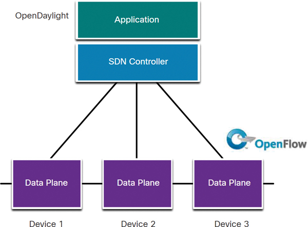
Figure 13-19 Controller-Based SDN
The applications can interface with the controller responsible for managing devices and manipulating traffic flows throughout the network. The Cisco Open SDN Controller is a commercial distribution of OpenDaylight.
Policy-Based SDN
Policy-based SDN is similar to controller-based SDN, where a centralized controller has a view of all devices in the network, as shown in Figure 13-20.
Policy-based SDN includes an additional policy layer that operates at a higher level of abstraction. It uses built-in applications that automate advanced configuration tasks via a guided workflow and user-friendly GUI. No programming skills are required. Cisco APIC-EM is an example of this type of SDN.
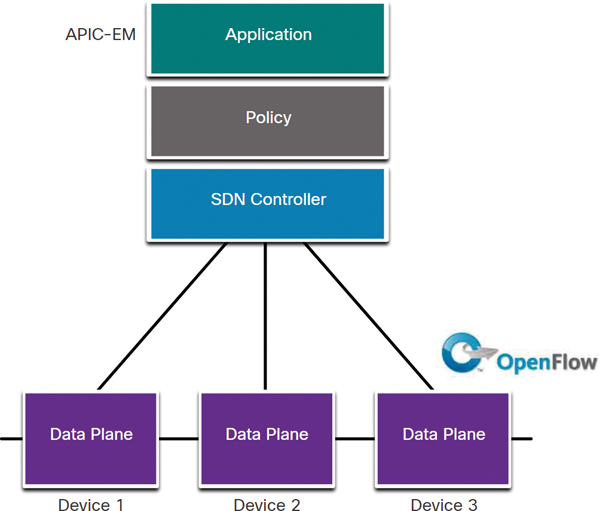
Figure 13-20 Policy-Based SDN
APIC-EM Features (13.5.6)
Each type of SDN has its own features and advantages. Policy-based SDN is the most robust, providing for a simple mechanism to control and manage policies across the entire network.
Cisco APIC-EM is an example of policy-based SDN. Cisco APIC-EM provides a single interface for network management that includes
Discovering and accessing device and host inventories
Viewing the topology (as shown in Figure 13-21)
Tracing a path between end points
Setting policies
APIC-EM Path Trace (13.5.7)
The APIC-EM Path Trace tool allows an administrator to easily visualize traffic flows and discover any conflicting, duplicate, or shadowed ACL entries. This tool examines specific ACLs on the path between two end nodes and displays any potential issues. You can see where any ACLs along the path either permitted or denied your traffic, as shown in Figure 13-22.
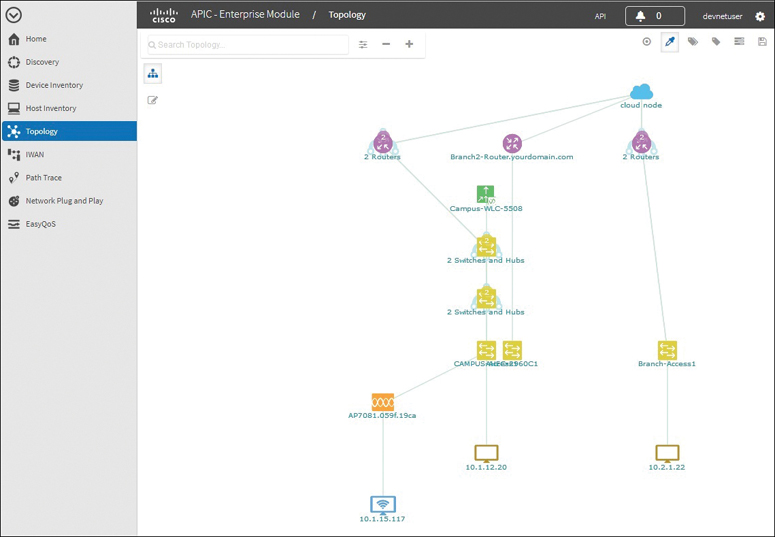
Figure 13-21 Topology Feature in the APIC-EM
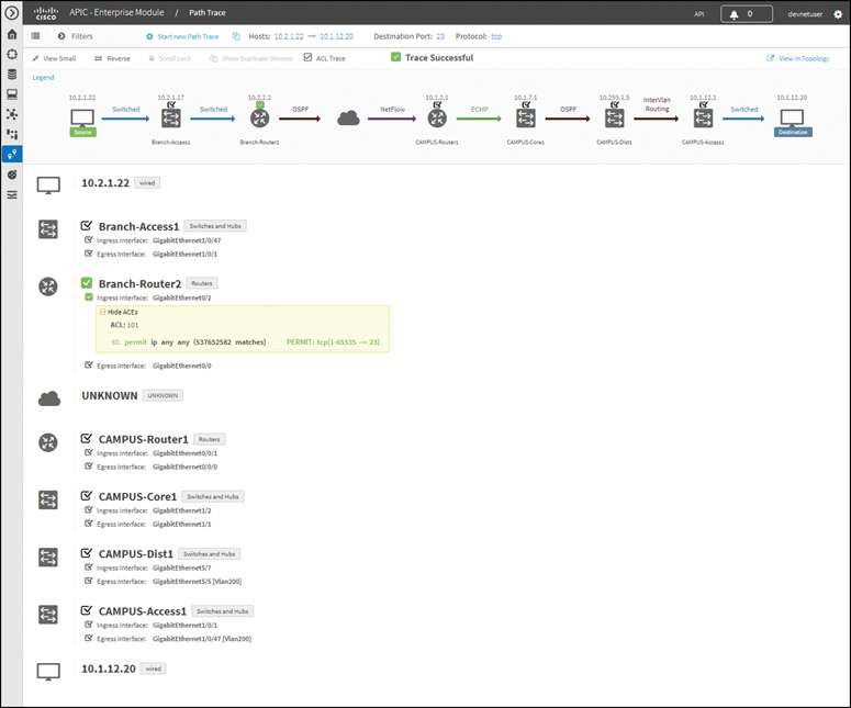
Figure 13-22 Example of an APIC-EM Path Trace
In this figure, notice how Branch-Router2 is permitting all traffic. Based on this information, the network administrator can, if necessary, make adjustments to filter traffic more effectively.
Check Your Understanding—Controllers (13.5.8)
Refer to the online course to complete this activity.
Summary (13.6)
The following is a summary of the sections in this chapter.
Cloud Computing
Cloud computing involves large numbers of computers connected through a network that can be physically located anywhere. Cloud computing can reduce operational costs by using resources more efficiently. Cloud computing addresses a variety of data management issues:
It enables access to organizational data anywhere and at any time.
It streamlines the organization’s IT operations by subscribing only to needed services.
It eliminates or reduces the need for onsite IT equipment, maintenance, and management.
It reduces costs for equipment, energy, physical plant requirements, and personnel training needs.
It enables rapid responses to increasing data volume requirements.
The three main cloud computing services defined by the National Institute of Standards and Technology (NIST) are software as a service (SaaS), platform as a service (PaaS), and infrastructure as a service (IaaS). With SaaS, the cloud provider is responsible for access to applications and services (such as email, communication, and Office 365) that are delivered over the internet. With PaaS, the cloud provider is responsible for providing users access to the development tools and services used to deliver the applications. With IaaS, the cloud provider is responsible for giving IT managers access to the network equipment, virtualized network services, and supporting network infrastructure. The four types of clouds are public, private, hybrid, and community. Cloud-based applications and services offered in a public cloud are made available to the general population. Cloud-based applications and services offered in a private cloud are intended for a specific organization or entity, such as the government. A hybrid cloud is made up of two or more clouds (for example, part private and part public), where each part remains a separate object but the two are connected using a single architecture. A community cloud is created for exclusive use by a specific community.
Virtualization
The terms cloud computing and virtualization are often used interchangeably; however, they mean different things. Virtualization is the foundation of cloud computing. Virtualization separates the operating system (OS) from the hardware. Historically, enterprise servers consisted of a server OS, such as Windows Server or Linux Server, installed on specific hardware. All of a server’s RAM, processing power, and hard drive space were dedicated to the service. When a component fails, the service that is provided by this server becomes unavailable. This is known as a single point of failure. Another problem with dedicated servers is that they often sit idle for long periods of time, waiting until there is a need to deliver the specific service they provide. This wastes energy and resources (server sprawl). Virtualization reduces costs because less equipment is required, less energy is consumed, and less space is required. It provides for easier prototyping, faster server provisioning, increased server uptime, improved disaster recovery, and legacy support. A computer system consists of the following abstraction layers: services, OS, firmware, and hardware. A Type 1 hypervisor is installed directly on a server or networking hardware. A Type 2 hypervisor is software that creates and runs VM instances. It can be installed on top of the OS or can be installed between the firmware and the OS.
Virtual Network Infrastructure
Using Type 1 hypervisors is also called the “bare metal” approach because a hypervisor is installed directly on the hardware. Type 1 hypervisors have direct access to hardware resources and are more efficient than hosted architectures. They improve scalability, performance, and robustness. Type 1 hypervisors require a management console to manage the hypervisor. Management software is used to manage multiple servers using the same hypervisor. The management console can automatically consolidate servers and power on or off servers, as required. The management console provides recovery from hardware failure. Some management consoles also allow server overallocation. Server virtualization hides server resources, such as the number and identity of physical servers, processors, and OSs, from server users. This practice can create problems if the data center is using traditional network architectures. Another problem is that traffic flows differ substantially from those in the traditional client/server model. Typically, a data center has a considerable amount of traffic being exchanged between virtual servers. These flows are called east–west traffic and can change in location and intensity over time. North–south traffic occurs between the distribution and core layers and is typically traffic destined for offsite locations such as another data center, other cloud providers, or the internet.
Software-Defined Networking
Two major network architectures have been developed to support network virtualization: software-defined networking (SDN) and Cisco Application Centric Infrastructure (ACI). SDN is an approach to networking in which the network is remotely programmable. SDN may include OpenFlow, OpenStack, and other components. An SDN controller is a logical entity that enables network administrators to manage and dictate how the data plane of switches and routers should handle network traffic. A network device contains a control plane and a data plane. The control plane is regarded as the brains of a device. It is used to make forwarding decisions. The control plane contains Layer 2 and Layer 3 route forwarding mechanisms, such as routing protocol neighbor tables and topology tables, IPv4 and IPv6 routing tables, STP, and the ARP table. Information sent to the control plane is processed by the CPU. The data plane, also called the forwarding plane, is typically the switch fabric connecting the various network ports on a device. The data plane of each device is used to forward traffic flows. Routers and switches use information from the control plane to forward incoming traffic out the appropriate egress interface. Information in the data plane is typically processed by a special data plane processor without the CPU getting involved. Cisco Express Forwarding (CEF) uses the control plane and data plane to process packets. CEF is an advanced Layer 3 IP switching technology that enables forwarding of packets to occur at the data plane without consultation of the control plane. SDN basically involves the separation of the control plane and data plane. The control plane function is removed from each device and is performed by a centralized controller. The centralized controller communicates control plane functions to each device. The management plane is responsible for managing a device through its connection to the network. Network administrators use applications such as Secure Shell (SSH), Trivial File Transfer Protocol (TFTP), Secure FTP, and Secure Hypertext Transfer Protocol (HTTPS) to access the management plane and configure a device. Protocols such as Simple Network Management Protocol (SNMP) use the management plane.
Controllers
An SDN controller is a logical entity that enables network administrators to manage and dictate how the data plane of switches and routers should handle network traffic. The SDN controller defines the data flows between the centralized control plane and the data planes on individual routers and switches. Each flow traveling through the network must first get permission from the SDN controller, which verifies that the communication is permissible according to the network policy. If the controller allows a flow, it computes a route for the flow to take and adds an entry for that flow in each of the switches along the path. The controller populates flow tables. Switches manage the flow tables. A flow table matches incoming packets to a particular flow and specifies the functions that are to be performed on the packets. There may be multiple flow tables that operate in a pipeline fashion. A flow table may direct a flow to a group table, which may trigger a variety of actions that affect one or more flows. A meter table triggers a variety of performance-related actions on a flow including the ability to rate limit the traffic. Cisco developed the Application Centric Infrastructure (ACI) as an advanced and innovative improvement over earlier SDN approaches. Cisco ACI is a hardware solution for integrating cloud computing and data center management. At a high level, the policy element of the network is removed from the data plane. This simplifies the way data center networks are created. The three core components of the ACI architecture are the Application Network Profile (ANP), the Application Policy Infrastructure Controller (APIC), and Cisco Nexus 9000 Series switches. The Cisco ACI fabric is composed of the APIC and the Cisco Nexus 9000 Series switches using two-tier spine-leaf topology. Unlike in SDN, the APIC controller does not manipulate the data path directly. Instead, the APIC centralizes the policy definition and programs the leaf switches to forward traffic based on the defined policies. There are three types of SDN. With device-based SDN, the devices are programmable by applications running on the device itself or on a server in the network. Controller-based SDN uses a centralized controller that has knowledge of all devices in the network. Policy-based SDN is similar to controller-based SDN, where a centralized controller has a view of all devices in the network. Policy-based SDN includes an additional policy layer that operates at a higher level of abstraction. Policy-based SDN is the most robust, providing a simple mechanism to control and manage policies across the entire network. Cisco APIC-EM is an example of policy-based SDN. Cisco APIC-EM provides a single interface for network management, including discovering and accessing device and host inventories, viewing the topology, tracing a path between endpoints, and setting policies. The APIC-EM Path Trace tool allows an administrator to easily visualize traffic flows and discover any conflicting, duplicate, or shadowed ACL entries. This tool examines specific ACLs on the path between two end nodes and displays any potential issues.
Lab—Install Linux in a Virtual Machine and Explore the GUI (13.6.1)
![]()
In this lab, you will install a Linux OS in a virtual machine, using a desktop virtualization application, such as VirtualBox. After completing the installation, you will explore the GUI interface.
Practice
The following lab provides practice with the topics introduced in this chapter. The lab is available in the companion Enterprise Networking, Security, and Automation Labs & Study Guide (CCNAv7) (ISBN 9780136634324). There are no Packet Tracer activities for this chapter.
Lab
![]()
Lab 13.6.1 Install Linux in a Virtual Machine and Explore the GUI
Check Your Understanding Questions
Complete all the review questions listed here to test your understanding of the topics and concepts in this chapter. The appendix “Answers to the ‘Check Your Understanding’ Questions” lists the answers.
1. Which of the following is the term for the extension of the internet structure to billions of connected devices?
BYOD
Digitization
IoT
M2M
2. Which cloud computing service would provide the use of network hardware such as routers and switches for a particular company?
Browser as a service (BaaS)
Infrastructure as a service (IaaS)
Software as a service (SaaS)
Wireless as a service (WaaS)
3. What technology allows users to access data anywhere and at any time?
cloud computing
data analytics
micromarketing
virtualization
4. Which cloud computing service would be best for a new organization that cannot afford physical servers and networking equipment and must purchase network services on demand?
IaaS
ITaaS
PaaS
SaaS
5. Which cloud model provides services for a specific organization or entity?
community cloud
hybrid cloud
private cloud
public cloud
6. What is a benefit of virtualization?
guarantee of power
improvement of business practices
supply of consistent air flow
support of live migration
7. What is a difference between the functions of cloud computing and virtualization?
Cloud computing provides services on web-based access, whereas virtualization provides services on data access through virtualized internet connections.
Cloud computing requires hypervisor technology, whereas virtualization is a fault-tolerance technology.
Cloud computing separates the application from the hardware, whereas virtualization separates the OS from the underlying hardware.
Cloud computing utilizes data center technology, whereas virtualization is not used in data centers.
8. Which of the following applies to a Type 2 hypervisor?
best suited for enterprise environments
does not require management console software
has direct access to server hardware resources
installs directly on hardware
9. Which is a characteristic of a Type 1 hypervisor?
best suited for consumers and not for an enterprise environment
does not require management console software
installed directly on a server
installed on an existing operating system
10. Which technology virtualizes the control plane and moves it to a centralized controller?
cloud computing
fog computing
IaaS
SDN
11. Which two layers of the OSI model are associated with SDN network control plane functions that make forwarding decisions? (Choose two.)
Layer 1
Layer 2
Layer 3
Layer 4
Layer 5
12. Which type of hypervisor would most likely be used in a data center?
Nexus 9000 switch
Oracle VM VirtualBox
Type 1
Type 2
13. Which type of hypervisor would most likely be used by a consumer?
Nexus 9000 switch
Oracle VM VirtualBox
Type 1
Type 2
14. What component is considered the brains of the ACI architecture and translates application policies?
Application Network Profile endpoints
Application Policy Infrastructure Controller
hypervisor
Nexus 9000 switch