understanding the technical constraints of creating for different digital media
by Rob Manton
by Rob Manton
Understanding the technical constraints of creating for different digital media
INTRODUCTION
Computer animation is an enormous and rapidly expanding field with many software products and techniques available. This chapter attempts to demystify the subject and to explain the reasoning that might help you to choose an appropriate animation package and file format for your animation project.
First, we look at some of the fundamental principles of computer graphics to help you understand the jargon and make sense of the options available in animation software packages.
Second, we look at the type of animation tools available. Many different packages implement tools based on the same general principles. This section will help you to identify the techniques that you need and help you find them in your chosen package.
Finally, we consider some of the issues that affect the playback of animation on various different delivery platforms. It is useful to understand the strengths and limitations of your chosen means of delivery before designing the animation.
When you have finished reading this chapter you will have a basic understanding of:
• The terminology used to describe computer graphics and computer animation.
• The types of animation package and their suitability for different applications.
• The standard animation techniques that are available in many animation packages.
• How to choose a file format suitable for your needs.
• How to prepare animation sequences for playback on your chosen delivery platform.
In the early days of commercial computer animation most sequences would be created on a physically large, expensive, dedicated machine and output onto video tape. Since then we have seen rapid developments in the capabilities of personal computers which have opened up many affordable new ways of creating animation on a general purpose computer, but also many new output possibilites for animation. These include multimedia delivered on CD-ROM, within web pages delivered over the Internet, on DVD and within fully interactive 3D games. Later in this chapter we consider the ways in which animation sequences can be prepared for delivery in these different media.
The early computer animations were linear. Video and television are inherently linear media. Many of the more recent developments including multimedia and the web have allowed user interaction to be combined with animation to create interactive non-linear media. The culmination of this process has been the development of 3D games where the user can navigate around and interact with a 3D environment. There is still a large demand for traditional linear sequences alongside the newer interactive applications, so we need to consider approaches to creating and delivering each kind of animation.
In computer graphics there are two fundamentally different approaches to storing still images. If I wanted you to see a design for a character I could either send you a photograph or sketch of it or I could describe it and you could draw it yourself based on my instructions. The former approach is akin to bitmap storage which is described shortly. The latter approach is akin to a vector representation.
If I want to show you a puppet show I can either film it with my video camera and send you the tape, or I can send a kit of parts including the puppets and some instructions about what to make the characters do and say. You can re-create the show yourself based on my instructions. The former approach is similar to the various digital video or video tape-based approaches. We can design the animation in any way we choose and send a digital video clip of the finished sequence. As long as the end user has a device capable of playing back the video file then we can be confident that it will play back properly. This approach is effectively the bitmap storage approach extended into the additional dimension of time.
Alternative approaches that delegate the generation of the images and movement to the user’s hardware include interactive multimedia products like Director or Flash, web pages using DHTML, computer games and virtual reality. These approaches shift some of the computing effort to the user’s equipment and can be thought of as an extension of the vector approach into the time dimension.
A few years ago the relatively slow nature of standard PCs made the former approach more viable. It was reasonably certain that most PCs would be able to play back a small sized video clip so the ubiquitous ‘postage stamp’ sized video or animation clip became the norm. Now that standard PCs and games consoles have much better multimedia and real time 3D capabilities, the latter approach is becoming more widespread. The file sizes of the ‘kit of parts approach’ can be much smaller than the ‘video’ approach. This has opened up some very exciting possibilities including virtual reality, games and 3D animation on the web.
SOME TECHNICAL ISSUES
Animation consists fundamentally of the creation and display of discreet still images. Still images in computer graphics come in many forms and in this section we attempt to describe some of the differences. Which type you need will depend on what you plan to do with it and this is discussed later in the chapter. Still images can be used in the creation of animation, as moving sprites in a 2D animation or as texture maps or backgrounds in a 3D animation for example. They can also be used as a storage medium for a completed animation, for recording to video tape or playing back on computer.
DISPLAY DEVICES
Animations are usually viewed on a television set, computer monitor or cinema screen. The television or computer image is structured as a ‘raster’, which is a set of horizontal image strips called scan lines. The image is transferred line by line onto the screen. This process, known as the refresh cycle, is repeated many times a second at the refresh frequency for the device.
In televisions the refresh cycle is broken into two intermeshing ‘fields’. All odd numbered scan lines are displayed first then the intermediate, even numbered scan lines are drawn second to ‘fill in the gaps’. This doubles the rate at which new image information is drawn, helping to prevent image flicker. For PAL television this doubles the effective refresh rate from 25 Hz (cycles per second) to 50 Hz. For NTSC this increase is from nearly 30 Hz to nearly 60 Hz. This works well if adjacent scan lines contain similar content. If they don’t and there is significant difference between one scan line and the next (as with an image that contains thin horizontal lines, like a newsreader with a checked shirt) then annoying screen flicker will occur.
Modern computer monitors refresh at a higher rate than televisions and are usually non-interlaced. If you have a PC you can examine the refresh frequency being used by looking in the display properties section in the Windows control panel. It is probably set to 75 Hz (cycles per second). Although the image on a computer screen is probably being refreshed (redrawn) 75 times a second, our animation doesn’t need to be generated at this rate. It is likely that the animation will be created at a much lower frame rate as we will see shortly.
BITMAP IMAGES AND VECTORS
We stated in the introduction to this chapter that computer graphics images are stored in one of two fundamentally different ways. Bitmaps are conceptually similar to the raster described above. This structure lends itself directly to rapid output to the computer display. The alternative is to use a vector description which describes the image in terms of a series of primitives like curves, lines, rectangles and circles. In order to convert a vector image into the raster format and display it on screen it has to be rasterized or scan-converted. This is a process that is usually done by the computer display software. You may also encounter these ideas when trying to convert vector images to bitmap images using a graphics manipulation program.
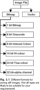
Fig. 2.1 Different formats for saving still images. Not all types are likely to be suitable for your requirements!
Bitmap images can be created from a range of sources: by rendering 3D images from a modeling and animation package, by scanning artwork, by digitizing video stills, by shooting on a digital camera, by drawing in a paint program or by rasterizing a vector file. They can also be saved as the output of an animation package. They comprise of a matrix of elements called pixels (short for picture elements). The colour or brightness of each pixel is stored with a degree of accuracy, which varies depending on the application.
A word about bits and bytes
In computing the most basic and smallest storage quantity is called a bit. A single bit can either be set on or off to record a 1 or 0. Bits are arranged in units of eight called bytes. Each bit in a byte is allocated a different weighting so that by switching different bits on or off, the byte can be used to represent a value between 0 (all bits switched off) and 255 (all bits switched on). Bytes can be used to store many different types of data, for example a byte can represent a single text character or can be used to store part of a bitmap image as we describe below. As the numbers involved tend to be very large it is more convenient to measure file sizes in kilobytes (kb – thousands of bytes) or megabytes (Mb – millions)
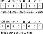
Fig. 2.2 A byte is a set of eight bits each with a different weighting. You can think of each bit as an on-off switch attached to a light-bulb of a differing brightness. By switching all of the lights on you get a total of 255 units worth of light. Switching them all off gives you nothing. Intermediate values are made up by switching different combinations.
Types of bitmap image
The colour depth or bit depth of a bitmap image refers to the amount of data used to record the value of each pixel. Typical values are 24 bit, 16 bit, 32 bit and 8 bit. The usefulness of each approach is described below.
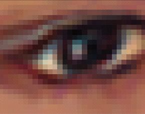
Fig. 2.3 A bitmap image close up. The image is composed of scan lines, each of which is made up of pixels. Each pixel is drawn with a single colour. Enlarging a bitmap image makes the individual pixels visible.
The simplest approach to recording the value of a pixel is to record whether the image at that point is closest to black or white. A single bit (1 or 0) records the value of the pixel, hence the approach is called a true bitmap. It has a bit depth of 1 bit. The monochrome image has stark contrast and is unlikely to be useful for much animation. Since it takes up the smallest amount of disk space of any bitmap, 1-bit images are sometimes useful where file size is at a premium, in some web applications for example. 1-bit images are sometimes used as masks or mattes to control which parts of a second image are made visible.
A greyscale image records the brightness of the pixel using a single byte of data which gives a value in the range 0–255. Black would be recorded as 0, white as 255. This has a bit depth of 8 bits (1 byte). Greyscale images are not very useful for animation directly, but may be useful as masks or for texture maps in 3D graphics.
Colour images are stored by breaking down the colour of the pixel into Red, Green and Blue components.
The amount of each colour component is recorded with a degree of precision that depends on the memory allocated to it. The most common type of colour image, called a true colour image uses a bit depth of 24 bits.
A single byte of data, giving a value in the range 0–255, is used to store each colour component. White is created with maximum settings for each component (255, 255, 255) and black with minimum values of each (0, 0, 0). As the term ‘true colour’ implies, they give a good approximation to the subtlety perceived by the human eye in a real scene. It is possible to store colour data at a higher resolution such as 48 bit, and this is sometimes used for high resolution print and film work.
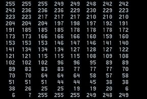
Fig. 2.4 The contents of a bitmap file. This is a 24-bit true colour file. Each value is a byte representing either the red, green or blue component of a pixel. Note how each value is between 0 and 255.
For images displayed on screen or T V, 24 bit is usually considered adequate as the eye is unable to perceive any additional subtlety. True colour images are the most common type that you will use for your animations although for some applications where image size and download speed are critical you may need to compromise.
A common alternative format is 16 bits per pixel (5 bits red, 6 bits green, 5 bits blue) which gives a smaller file size but may not preserve all the subtlety of the image. You would be unlikely to accept a compromise for television or video output, but for multimedia work the saving in file size may be justified.
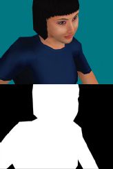
Fig. 2.5 A 32-bit image containing the 24-bit visible image and the 8-bit alpha channel. The alpha channel is used when compositing the image over another background as shown below.
32-bit images contain a standard 24-bit true colour image, but with an extra component called an alpha channel. This is an additional 8-bit mono image that acts as a stencil and can be used to mask part of the main image when it is composited or placed within an animation sequence. This alpha channel can also come into play when the image is used as a texture map within a 3D modeling program. Unless you need the alpha channel then saving images as 32 bit may waste disk space without giving any benefit. You should save as 24 bit instead.

Fig. 2.6 Character, produced by Dave Reading at West Herts College for the Wayfarer game.
An alternative way of recording colour information is to use a colour palette. Here a separate ‘colour look-up table’ (CLUT) stores the actual colours used and each pixel of the image records a colour index rather than a colour directly. Typically a 256-colour palette is used. Indexed colour images have the advantage that they only require 1 byte or less per pixel. The disadvantage is that for images with a large colour range, the limitation of 256 different entries in the palette may cause undesirable artefacts in the image. These include colour banding where subtle regions of an image such as a gentle sunset become banded.
Indexed colour (8-bit) images are useful when the content contains limited numbers of different colours. Menus and buttons for interactive programs can be designed with these limitations in mind. 8-bit images with their reduced file size are sometimes used within CD-ROM programs or computer games where their smaller size helps to ensure smooth playback and limits the overall file size of the sequence. For high quality animation work intended for output to video or television you should save images in true colour 24 bit.
Vector images
Vector images record instructions that can be used to reconstruct the image later. Vector images can be created by drawing them in a drawing package or by the conversion of a bitmap image. They contain objects like spline curves, which are defined by a relatively small number of control points. To save the file only the position and parameters of each control point need to be stored. When viewed on a monitor, vector images are rasterized by the software. This process effectively converts the vector image to a bitmap image at viewing time. Vector images have a number of benefits over bitmap images. For many types of image they are much smaller than the equivalent bitmap. This makes vector images an attractive alternative for use on the Internet.
Secondly, vector images are resolution independent. This means that they can be viewed at different sizes without suffering any quality loss. Bitmap images are created at a fixed resolution as explained in the next section.
Vector images cannot be used to represent all types of image. They are typically used for storing computer-drawn artwork including curves and text. Scanned photographs and other images with large amounts of colour and image detail are difficult to convert usefully to vectors. Packages like Adobe Streamline and Macromedia Flash attempt this conversion but it is often necessary to compromise significantly on image quality in order to achieve a small sized vector image from a bitmap original. Images with photographic realism are not suitable for this process, but more simplified cartoon style images are. This accounts for the cartoon-like look of many images within Flash animations.
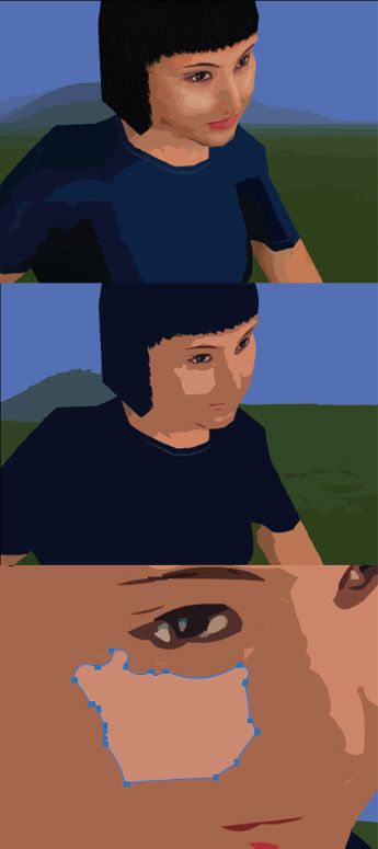
Fig. 2.7 A bitmap image converted to vector form in Flash. Note how each area of colour has been converted into a filled polygon. The high and low quality versions shown above take 39 kb and 7 kb of disk space respectively. The more detail recorded, the higher the number of polygons or curves stored and the larger the vector file size. Vector files are more effective for storing cartoon style line artwork. Photorealistic images do not usually lend themselves well to vector storage.
The resolution of a bitmap image is defined as the number of pixels per unit distance. The term is also sometimes (sloppily) used to describe the number of pixels that make up the whole bitmap. Since we are unlikely to be outputting animation to paper we are more interested in the required image size for our animations. This influences both the quality of the image and its file size (the amount of data that will be required to store it). The image size needed for an animation varies depending on the output medium.
There are a bewildering number of sizes for television output. This variety is due to the different standards for PAL and NTSC but also due to variations in output hardware. Even though the number of scan lines is fixed for each television standard, different horizontal values are possible depending on the aspect ratio of image pixels used in particular hardware. For systems using square pixels such as the Miro DC30 video card, graphics for PAL output should be 768 by 576 pixels. Systems using non square pixels such as the professional AVID NLE system typically require either 704 by 576 pixels or 720 by 576. NTSC systems require either 720 × 486 or 640 by 480. High Definition (HD) Widescreen format is now becoming available which further adds to the confusion. This uses a much larger number of image scan lines, 1920 × 1080 or 1280 × 720. You should check the specific requirements of your hardware before preparing animation for output to television.
The amount of data required to store an image (without compression, which is discussed below) can be calculated as follows:
Data to store image (bytes) = width (pixels) × height (pixels) × number of bytes per pixel
For a typical 720 by 576 PAL video image this would be 720 × 576 × 3 (3 bytes per pixel for an RGB image)
= 1 244 160 bytes
= 1.244 Megabytes (Mb)
In contrast to vector images, which are resolution independent, bitmap images are created at a fixed resolution. If images were created at say 320 by 240 pixels and enlarged for output to video, then the individual pixels would become visible, giving an undesirable blocky look. For television or video work the quality of the finished sequence is paramount and you should ensure that the images are created at the correct size.
For CD-ROM or web applications the size of the files are constrained by the speed of the CD-ROM drive or the Internet connection. For CD-ROM work 320 by 240 pixels is a common size for bitmap-based animation and video files. In the medium term the restrictions caused by computing hardware and the speed of the Internet will ease and full screen video will become the norm on all delivery platforms. Vector-based animation files like Macromedia Flash are not limited in the same way. Because they are resolution independent, Flash animations can be scaled to larger sizes without reduction in image quality.
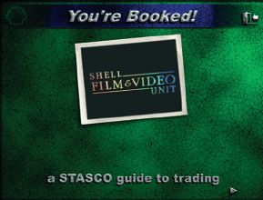
Fig. 2.8 The introduction sequence for the Shell Film & Video Unit CD-ROM You’re Booked!. Note how the animation (the logo in the frame) is contained within a small screen area. This ensures smooth playback on relatively slow CD-ROM drives.
FRAME RATE
As explained in the first chapter, there is no fixed frame rate that is applicable to all animation. Television works at 25 f.p.s. (PAL) or 30 f.p.s. (NTSC). Film runs at 24 f.p.s. Technical limitations may require animation sequences for delivery from computers to be created at lower frame rates. The vector-type animation files that require real time rendering on the user’s machine can play significantly slower than the designed rate on older hardware. Most interactive products have a minimum hardware specification defined. During the development process the animation or interactive product is tested on computers of this minimum specification to identify and resolve these playback problems. If you are creating Flash, Director or other interactive content be sure to test your work regularly on the slowest specification of hardware that you intend to support. It is relatively easy to create amazing eye-catching content to work on high spec hardware. To create eye-catching content that works properly on low spec hardware is more of a challenge!
DATA RATES AND BANDWIDTH
The data rate of a media stream like a video, animation or audio clip refers to the amount of data per second that has to flow to play back that sequence. For an uncompressed bitmap animation sequence this is simply the size of a single image multiplied by the number of frames per second (the frame rate).
So for 720 by 576 uncompressed PAL video the data rate is 1.244 Mb per image × 25 frames per second = 31.1 Mb/s.
For vector animation typified by Macromedia Flash, the data rate required is determined by the complexity of the images in the sequence rather than the size of the frame and is very difficult to estimate in advance.
Bandwidth refers to the ability of a system to deliver data. If the data rate of a data stream (like a digital video file) is higher than the bandwidth available to play it back then the data stream will not play properly.
As an example, the theoretical maximum bandwidth deliverable from a 16-speed CD-ROM drive is 2.5 Mb/s. (Note that the graphics card and system bus also contribute to providing bandwidth as well as the CD-ROM or hard disk. Poor quality components can slow down the overall performance of your system.)
In order to ensure smooth playback on such a system the data rate of the video sequence would need to be significantly reduced. This can be achieved by reducing the image size (typically to 320 by 240 for animation played back on CD-ROM), the frame rate (typically to 15 f.p.s. – below this level the effect is annoying and any lip synchronization is lost) and applying compression, which is discussed next.
The high end computers equipped for professional Non-Linear Video Editing typically have AV (audio-visual) spec hard disks with a bandwidth of 25–35 Mb/s. These are capable of playing back non-compressed video files. Amateur or semi-professional hardware may only be capable of 2–10 Mb/s. If you have a video editing card installed in your system there should be a software utility that will help to measure the maximum bandwidth for reading or writing to your hard disk.
At the other extreme of the bandwidth spectrum is the Internet. Home users connected to the net via a standard modem may experience a bandwidth as low as 1 kb/s (0.001 Mb/s) on a bad day. In order to create your animation sequence so that it will play back properly, you need to take into consideration the bandwidth available to your end user.
Compression refers to the ways in which the amount of data needed to store an image or other file can be reduced. This can help to reduce the amount of storage space needed to store your animation files and also to reduce the bandwidth needed to play them back.

Fig. 2.9 Setting the compression ratio when capturing video on the Miro DC30 video card. Saving your sequences with low compression settings will maintain picture quality but create huge files that don’t play back smoothly. Applying too much compression may spoil your picture quality.
Compression can either be lossless or lossy. With lossless compression no image quality is lost. With lossy compression there is often a trade-off between the amount of compression achieved and the amount of image quality sacrificed. For television presentation you would probably not be prepared to suffer any quality loss, but for playback via the web you might sacrifice image quality in order to achieve improvements in playback performance. Compression ratio is defined as the ratio of original file size to the compressed file size. The higher the amount of lossy compression applied, the poorer the image quality that results.
Spatial compression
Spatial compression refers to techniques that operate on a single still image. Lossless spatial compression techniques include LZW (used in the .GIF format) and Run Length Encoding. This latter approach identifies runs of pixels that share the same colour and records the colour and number of pixels in the ‘run’. This technique is only beneficial in images that have large regions of identical colour – typically computer generated images with flat colour backgrounds.
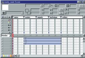
Fig. 2.10 The main timeline in Macromedia Director. Image layers are on the vertical axis and frames on the horizontal axis.
Lossy spatial techniques include JPEG compression, which achieves its effect by sacrificing the high frequencies (fine detail) in the image. As a result artefacts (unwanted side effects) like pixellation and blurring of fine detail can occur.
Digital video files can be stored in MJPEG format, which uses these techniques and can achieve compression ratios in the range 2:1 to 50:1. This format is used for storing sequences that are subsequently to be edited or post-processed. Playback of MJPEG files is usually only possible on PCs fitted with special video capture and playback hardware and fast AV hard disk drives. It is ideal for storage and playback from these machines as it gives the optimum image quality, however, it is unsuitable for general distribution as standard PCs are unable to play this format.
The choice of an appropriate compression method may have a significant impact on the visual quality and playback performance of a multimedia, web or game animation. For television or video work a poor choice of compression method may impair your final image quality.
Temporal compression
Temporal compression refers to techniques that consider how images in a video or animation sequence change over time. An animation or video sequence may comprise of a relatively small changing area and a static background. Consider the ubiquitous flying logo sequence. If the logo moves against a static background then the only parts of the image that change from frame-to-frame are the ones visited by the moving logo. Temporal compression aims to save on space by recording only the areas of the image that have changed. For a small object moving against a static background it would be possible to store the entire image in the first frame then subsequently just record the differences from the previous frame. Frames that record only those pixels that have changed since the previous frame are called Delta frames.
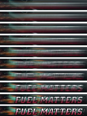
Fig. 2.11 A sequence of frames created for the title sequence to the Shell Film & Video Unit CD-ROM Fuel Matters!. Each frame has been subjected to different amounts of blurring in Photoshop and the whole sequence is assembled in Director. The effect is for the title to snap into focus.
In practice it is often necessary to periodically store complete frames. These complete frames are called keyframes and their regularity can often be specified when outputting in this format.
The regular keyframes have two important benefits. If the entire scene changes, for example when there is a cut in the animation or if the camera moves in a 3D sequence, then the keyframe ensures that the complete image is refreshed which contributes to ensuring good image quality. Secondly, the regular keyframes ensure that it is possible to fast forward and rewind through the animation/video clip without an unacceptable delay. This may be important if your animation sequence is to be embedded in a multimedia product and pause and fast forward functionality is required.
The degree of compression achieved depends on the area of the image which remains static from frame to frame and also on the regularity of keyframes. Because keyframes occupy more file space than delta frames, excessive use of keyframes will restrict the potential compression achieved. Where no fast forward or rewind functionality is required and where the sequence has a completely static background throughout and a relatively small screen area occupied by the moving parts, it may be beneficial to restrict the number of keyframes to just 1.
Note that with some kinds of animation there is no saving to be achieved by temporal compression. If all pixels in an image change every frame, for example when the camera is moving in a 3D animation, then temporal compression will be unable to achieve any reduction in file size. The only option will be to rely on more lossy spatial compression.
Temporal compression is implemented by codecs like Cinepak and Sorenson. It is often a matter of trial and error to achieve the optimum settings for keyframe interval for a particular animation or video sequence. Temporal compression is appropriate for the storage of final animation or video sequences where maximum compression is necessary to achieve smooth playback from a limited bandwidth device. Where rapid motion exists in the sequence temporal compression can introduce undesirable artefacts like image tearing. As further editing would exaggerate and amplify these artefacts, this format is unsuitable for subsequent editing and post-processing.
TYPES OF SOFTWARE USED IN ANIMATION
Having discussed some of the main ideas involved in storing images and animation and video sequences we are now in a position to consider some of the main types of software package that you are likely to use when creating your animations. Although many different packages are available, they mostly fall into one of the categories described in this section. There are a finite number of animation techniques available and each individual software package will implement only some of them. Many packages are designed to be extended with third party plug-ins (additional software components that can be added to the main software), so even if your chosen package doesn’t implement one of the techniques described, it is possible that the functionality will be available via a plug-in from a third party supplier.
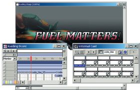
Fig. 2.12 The frames imported into Director and added to the timeline. Note how the changing area of the image is tightly cropped. The background remains constant. It would waste disk space and slow down playback performance if each image had to be loaded in full. This is a kind of manual temporal compression.
2D sprite animation packages
The term ‘sprite’ was originally applied to the moving images in the early arcade games. Today it can be used to mean any image element that is being manipulated in a 2D animation package. Most 2D animation tools allow scenes to be built up from individual image elements, which are either drawn within the package or imported from an external file. Some work primarily with bitmap images and others with vector images or a combination of the two. Macromedia Director was originally designed to work with bitmaps but more recently vector image support has been added. Macromedia Flash started as a vector animation tool but has support for bitmap images built in.
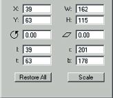
Fig. 2.13 Some of the sprite properties available in Director. In a 2D animation package, sprites (individual image elements) are usually positioned in pixels relative to the top left corner of the visible screen area. Here the X and Y values give the position of the object and the W and H values give its width and height.
A typical 2D animation tool provides a timeline-based interface showing image layers on the vertical axis and frames on the horizontal axis.
Sprites are individual image elements that are composited (combined) over a background while a program runs. Different combination styles may be available such as varying the opacity or colour of the sprite.
Each sprite can be modified by adjusting parameters such as its position, scale and rotation. The position of the sprite is usually specified in pixel co-ordinates from the top left corner of the screen.
For reasons of efficiency many packages treat images and other elements as templates which are often collected together in some kind of library. In Macromedia Director the images are termed ‘cast members’ and the library is called a ‘cast’. In Macromedia Flash the images are called symbols and the library is indeed called the library.
To assemble frames of the animation, the designer allocates the image templates stored in the library to the appropriate frame on the timeline. Although the terminology varies from package to package, the principle is the same. In Director, each time a cast member is placed on the timeline it is referred to as a sprite. In Flash, each use of a library symbol item in the timeline is called an instance.
When the animation file is stored, only the original image ‘template’ needs to be stored along with references to where and when each one appears in the animation timeline. This means that an image can be used multiple times without adding significantly to the file size. A Flash file of a single tree would probably take nearly the same amount of download time as a forest made up of many instances of the same tree template. The size, position and rotation of each instance can be adjusted individually.
Creating animation with 2D sprite animation packages
In this section we look at some of the techniques available for creating animation with a 2D package.
The simplest technique is to manually create each frame of the animation sequence. Each frame could be drawn using a paint or drawing program or drawn on paper and then scanned in. The software is used to play back the frames at the correct frame rate – a digital version of the traditional ‘flick book’.
An equivalent approach is to manually position image sprites in each frame of a sequence. This is akin to the way traditional stop-frame animators work.
Onion skinning is a feature available on many of these programs. This allows the user to create a sequence of images using drawing tools while seeing a faint view of the previous image or images in the sequence. This is helpful in registering the images.
Rotoscoping is a process involving the digitizing of a sequence of still images from a video original. These still images can then be modified in some way using paint or other software and then used within an animation or video sequence. Adobe Premiere allows digital video files to be exported in a film strip format which can be loaded in an image editing program like Adobe Photoshop for retouching.
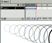
Fig. 2.14 Simple keyframe sequence in Flash. The position and size of the object has been defined at two separate keyframes and is being tweened. Onion skinning is used to display all the frames. The equal spacing of the object’s positions creates a movement that occurs at constant speed then comes to an abrupt and unnatural stop.
SPLINE-BASED KEYFRAME ANIMATION
The technique of manually positioning different elements in consecutive frames is labour intensive and requires considerable skill to achieve smooth results. As described in the first chapter, most computer animation tools provide a way of animating using keyframes. These are points in time where transform (the position, rotation, scale) or any other parameter of an element is defined by the animator.
The great efficiency benefits over the manual animation approach are provided by inbetweening (also known as tweening). This is the mechanism that interpolates the values defined at the keyframes and smoothly varies them for the intermediate frames. In this way a simple straight-line movement can be created by defining keyframes at the start and end points.
Keyframes have to be added by the user using the appropriate menu selection or keyboard shortcut.
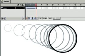
Fig. 2.15 The effect of applying ease out on a tweened animation in Flash. Note how the positions of the object are more bunched up towards the end of the movement on the right-hand side. This gives the effect of a natural slowing down.
They can usually be adjusted either by interactively positioning an element or by typing in values. In Director sprites can be dragged or nudged using the keyboard or can be typed in via the sprite inspector palette.
Two keyframes are adequate to define a straight-line movement. With three or more, complex curved motion is possible.
As described in the first chapter, the physics of the real world causes objects to accelerate and decelerate at different times. Objects dropped from rest, for example, start slowly and accelerate due to gravity. Cars start slowly, accelerate, decelerate and gradually come to a halt. These kind of dynamics can be approximated by using the ease-in and ease-out features provided by some software. Ease-in causes the object to start slowly and then accelerate. Ease-out does the opposite, gradually slowing down the motion.
Not only can the position, rotation and scale of each element be animated, but other settings that modify how the elements look. It may be possible to animate the opacity (visibility) of elements by setting different opacity values at keyframes.
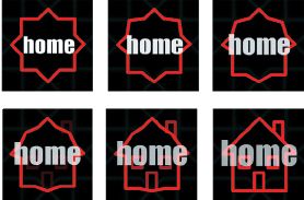
Fig. 2.16 The sequence of frames created for an animated button in the Shell Film & Video Unit CD-ROM PDO Reflections and Horizons. The series of morph images are created in Flash using the shape tweening feature. Some elements that are not part of the shape tween simply fade up.
2D MORPHING
Morphing is the process that smoothly interpolates between two shapes or objects. There are a number of different types of morphing that can apply to images or 2D shapes or a combination of the two. With a 2D animation program like Macromedia Flash you can morph between two 2D shapes made up of spline curves. This process is termed shape tweening. In order to help define which parts of the first shape map to which parts of the second shape, shape hints can be manually defined.
USING READY-MADE ANIMATIONS
You will be able to import and use various kinds of ready-made animation file. Digital video files, Flash movies, animated GIFs and various other kinds of animation or interactive content can often be imported and reused.
OUTPUT OPTIONS
Most 2D animation tools provide an output option to a digital video format like AVI or Quicktime or a sequence of still images. For output to video or television this will be appropriate, however, for playback from computer there are two reasons why this may not be your first choice. The first reason is to do with efficiency. The original 2D animation file is likely to be much more compact than a rendered digital video output. For playback of Flash animation on the Internet for example, this reduced file size is a significant selling point. The second reason is to do with interactivity. Pre-rendering the animation forces it to be linear. Leaving the generation of playback images to runtime allows for user interaction to influence and vary what happens in the animation. Examples of file formats that work in this way include the Flash .swf format and the Director projector (.exe).
3D MODELING AND ANIMATION
As in the real world, what you see of a 3D scene depends on the viewpoint that you are looking from. In a 3D modeling package you create a 3D world and then define a camera to view it with. A typical interface for a 3D modeling and animation package uses multiple viewports that display different views of the 3D world being created. These can include a combination of orthogonal (square-on, non-perspective) views like top, front, right which help you to assess the relative sizes and positions of the elements in your scene, and perspective views which help you to visualize them in 3D. The designer is able to refer to multiple views to fully understand the relationship of the objects and other elements in the virtual world.
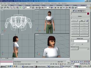
Fig. 2.17 The user interface of 3DS Max, a typical 3D modeling and animation package. Note how the different viewports give different information about the 3D object. Character produced by Dave Reading for the Wayfarer game at West Herts College.
Viewing the 3D scene
The objects in the 3D world can be built with a variety of techniques, which are described later, but in order to display the view that can be seen from the given viewpoint, all objects are converted to triangles. Each triangle is comprised of edges which each connect two vertices.
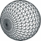
Fig. 2.18 A 3D sphere. Most 3D objects are built from triangles which are comprised of three edges connecting three vertices. The location of each vertex in 3D space is given by an x, y, z co-ordinate.
The positions of each vertex are defined in 3D co-ordinates. To view the scene, a viewing frustrum (a prism that defines the visible areas of the 3D world as seen from the viewing position) is first used to identify and discard those triangles that fall outside the visible area. This process, known as clipping, reduces the amount of processing done at the latter stages. Further processing is applied to achieve hidden surface removal, so that polygons completely occluded by others (covered up) are not processed. The locations of each vertex are mapped onto a flat viewing plane to give the flat projected view that is shown on screen.
This is sufficient to see the shape of the geometry (3D objects) that you have created as a wireframe however, it is more useful to display the 3D objects as solids. This process of calculating what the solid view looks like is called rendering. The most common type is photorealistic rendering which seeks to mimic the real world as closely as possible. Other types of non-photorealistic rendering include cartoon style (‘toon’ rendering) and various other special effects.
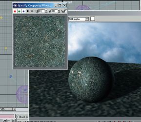
Fig. 2.19 A 24-bit true colour image for use as a texture map and a 3D object with the texture map applied.
Rendering the 3D scene
Rendering requires light sources to be created and surface properties to be defined for the geometry. The rendering process generates an image of the scene (usually a bitmap), taking into account the light falling on each visible polygon in the scene and the material defined for it. The way that this calculation is done varies according to the shader that you choose. These are algorithms developed by and named according to researchers in the computer graphics field like Phong and Blinn. Some shaders are more computationally expensive (slower to process) than others and some are more realistic. Photorealistic shaders provide approximations to the way things appear in the real world. Non-photorealistic shaders create different stylistic effects.
Part of the job of the designer and animator is to choose material properties for the objects in the 3D scene. Materials can be selected from a library of ready-made ones or created from scratch. Material properties usually include the colour values that are used in the lighting calculations. It is also common to define texture maps to vary material properties across the surface of the object. These textures can make use of bitmap images or procedural textures which use mathematical formulae to generate colour values. Procedural maps are useful for generating realistic natural looking surfaces.
Rendering time
Factors that influence the time taken to render a scene include the processor speed of the computer and the amount of RAM memory, the number of polygons in the scene, the number of light sources, the number and size of texture maps, whether shadows are required and the size of the requested bitmap rendering. Complex scenes can take minutes or even hours to render. Final rendering of completed sequences is sometimes carried out by collections of networked computers known as ‘rendering farms’. It is important as you create animations to perform frequent low resolution test renders to check different aspects of your work. You might render a few still images at full quality to check the look of the finished sequence and then do a low resolution rendering of the whole sequence perhaps with shadows and texturing switched off to check the movement. It is a common mistake by novice animators to waste lots of time waiting for unnecessary rendering to take place.
For applications that render 3D scenes in real time the number of polygons is the crucial factor. Computer games’ platforms are rated in terms of the number of polygons that they can render per second. The combined memory taken up by all the texture maps is also significant – if they all fit within the fast texture memory of the available graphics hardware then rendering will be rapid, if they don’t then slower memory will be used, slowing down the effective frame rate. As a result, games designers use small texture maps, sometimes reduced to 8 bit to save texture memory.
MODELING TECHNIQUES
Primitives and parametric objects
Most 3D modeling tools offer a comprehensive range of 3D primitive objects that can be selected from a menu and created with mouse clicks or keyboard entry. These range from simple boxes and spheres to special purpose objects like terrains and trees. The term parametric refers to the set of parameters that can be varied to adjust a primitive object during and after creation. For a sphere the parameters might include the radius and number of segments. This latter setting defines how many polygons are used to form the surface of the object, which only approximates a true sphere. This might be adjusted retrospectively to increase surface detail for objects close to the camera, or to reduce detail for objects far away.
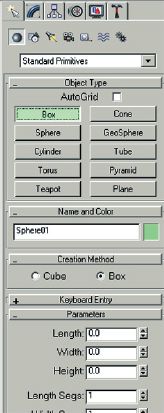
Fig. 2.20 The Geometry creation menu in 3DS Max. These primitive shapes are parametric which means that you can alter parameters such as the length, width and height of the box as shown.
Standard modeling techniques
The standard primitives available are useful up to a point, but for more complex work modeling can involve the creation of a 2D shape using spline curves or 2D primitives like rectangles and circles. The 2D shape is then converted to 3D in one of several ways.
The simplest approach is extrusion. A closed 2D polygon is swept along a line at right angles to its surface to create a block with a fixed cross-sectional shape.
Lathing is a technique that takes a 2D polygon and revolves it to sweep out a surface of revolution. This approach is useful for objects with axial symmetry like bottles and glasses.
Lofting is an extension of extrusion that takes an arbitrary 2D shape as a path (rather than the straight line at right angles to the surface) and places cross-sectional shapes along the path. The cross-sectional shapes which act as ribs along the spine created by the path can be different shapes and sizes. Lofting is useful for complex shapes like pipes and aircraft fuselages.

Fig. 2.21 Different approaches to modeling 3D objects. A 3D logo is created by extruding a 2D type object.
3D digitizing
Just as 2D images can be acquired by scanning 2D artwork, 3D mesh objects can be created by digitizing physical objects. 3D scanners come in various types, some based on physical contact with the object and some based on laser scanning. The resulting mesh objects can be animated using the skin and bones approach described below. Characters for games and animated motion pictures are often digitized from physical models. Ready digitized or modeled 3D geometry can also be purchased allowing you to concentrate on the animation.
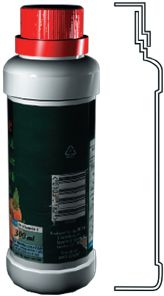
Fig. 2.22 A 2D shape is lathed to create a complete 3D bottle. Mathematically this is known as a surface of revolution. A complex shape like a saxophone can be created by lofting – placing different cross-sectional ribs along a curved spine shape.
Modifiers
Modifiers are adjustments that can be added to a 3D object. Modifiers include geometric distortions like twists and bends which change the shape of the object to which they are applied. The individual nature of each modifier is retained so their parameters can be adjusted or the modifier removed retrospectively.
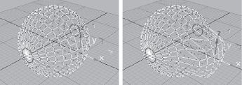
Fig. 2.23 Polygon modeling: a group of vertices on the surface of a sphere have been selected and are being pulled out from the rest of the object. This technique allows skilled modelers to create free form geometry with minimal numbers of polygons, which is important for performance in real time games.
For more flexible sculpting of 3D objects it is sometimes useful to convert objects created with primitives and modifiers into polygonal meshes. Consider a 3D sculpture made out of chickenwire and imagine that it was made out of elastic wire that could be stretched. Polygonal mesh-based objects can be sculpted by selecting vertices or groups of vertices and manipulating them by moving, scaling and adding modifiers. The disadvantage of the mesh-based approach is that the designer doesn’t have access to any of the original creation parameters of the shape. Polygonal mesh-based modeling is an artform that is particularly important for 3D game design where low polygon counts have to be used to achieve good performance.
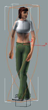
Fig. 2.24 Dave Reading’s Rachel character with a twist modifier attached. Modifiers can be used to adjust the shape of other objects, giving you great freedom to create unusual objects.
NURBS
NURBS (Non-Uniform Rational B-Spline) curves can be used to create complex 3D surfaces that are stored as mathematical definitions rather than as polygons. They are the 3D equivalent of spline curves and are defined by a small number of control points. Not only do they make it possible to store objects with complex surfaces efficiently (with very small file size) but they also allow the renderer to draw the surface smoothly at any distance. The renderer tesselates (subdivides it into a polygonal mesh) the surface dynamically so that the number of polygons used to render it at any distance is sufficient for the curve to look good and run efficiently. NURBS are good for modeling complex 3D objects with blending curved surfaces such as car bodies. Think of NURBS’ surfaces as a kind of 3D vector format that is resolution independent. Contrast this to the polygonal mesh which is more like a bitmap form of storage in that it is stored at a fixed resolution. If you zoom into a NURBS’ surface it still looks smooth. If you zoom into a polygonal mesh you see that it is made up of flat polygons.
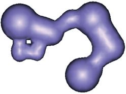
Fig. 2.25 An organic object modeled with metaballs. This modeling tool is akin to combining lumps of clay together.
Metaballs
Metaballs are spheres that are considered to have a ‘force’ function which tails off with distance. A collection of metaballs is arranged in 3D and converted to a polygonal mesh by the calculation of the surface where the sum total effect of the ‘force function’ of each metaball gives a constant value. They are useful for modeling organic shapes. The effect is similar to modeling a physical object by sticking lumps of clay together. Metaball modeling may be available as a plug-in for your 3D modeling package.
ANIMATING 3D WORLDS
The core set of animation techniques available to 2D animation packages is still available to 3D ones. As described earlier, the equivalent of the ‘stop frame’ approach is to manually position objects at each frame of an animation. Computer animation novices sometimes use this approach simply because they are unaware of the more efficient keyframe technique. This technique effectively creates a keyframe at every frame of the sequence.
Keyframe animation
Keyframe animation is the staple method for animating 3D objects. The transform (combination of position, scale and rotation) applied to each visible object in the scene (a combination of translation, rotation and scaling) can be animated by applying different values at different times. The software interpolates these values to smoothly vary them in the intermediate frames. This technique is useful for animating individual rigid bodies like our friend the flying logo but also for moving lights and cameras around the scene. Other properties of the 3D scene such as material properties like the opacity of a surface or modifier parameters like the amount of distortion applied may also be animated with keyframes. There is typically a visual keyframe editor to show how the value being animated varies with time and a keyboard entry approach for adjusting keyframes.
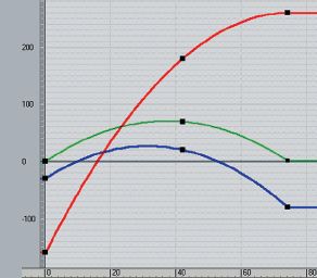
Fig. 2.26 The track view window in 3DS Max. The curves show how the x, y and z positions of an object are interpolated between the keyframes which are shown as black squares. Note that a smooth spline curve is used to interpolate each parameter in this case.
LINKED HIERARCHIES
For more complex work it is frequently necessary to link objects together. Consider the robot shown in fig. 1.30. A ‘child object’ such as a foot might be linked to a ‘parent object’ like the lower leg. The child object inherits the transformation from its parent, so if the robot was moved the legs and arms would stay connected and move with it. The foot has its own local transformation which means that it is able to rotate relative to the rest of the leg. Each object has a pivot point which acts at the centre for movement, rotation and scaling. In order for the foot to pivot correctly its pivot point must be moved into a suitable position (in this case the ankle).
Forward kinematics refers to the traditional way of posing a linked hierarchy such as a figure. The process frequently requires multiple adjustments: the upper arm is rotated relative to the torso, then the lower arm is rotated relative to the upper arm, then the hand is rotated relative to the lower arm. Forward kinematics is a ‘top down’ approach that is simple but tedious. The figure or mechanism is ‘posed’ at a series of keyframes – the tweening generates the animation.
Inverse kinematics
Inverse kinematics allows the animator to concentrate on the position of the object at the end of each linked chain. This end object is called the end effector of the chain. It might be at the tip of the toe or the fingers. IK software attempts to adjust the rotations of the intermediate joints in the chain to allow the animator to place the end effector interactively. The success of IK depends on the effort put in to defining legal rotation values for the intermediate joints. For example, an elbow or knee joint should not be allowed to bend backwards. Minimum and maximum rotations as well as legal and illegal rotation axes can be specified.
Skin and bones animation
A linked hierarchy can be used to build a character which is then animated with forward or inverse kinematics. Because the figure is composed of rigid objects linked together the .technique is more appropriate for robots and machinery rather than natural organisms and realistic characters. These can be created more realistically by bending and posing a single continuous character mesh.

Fig. 2.27 A character produced by Dave Reading for the Wayfarer game at West Herts College. The character is created as a single mesh object and textured (shown cutaway here for clarity). A bones system is added and animated using inverse kinematics techniques.
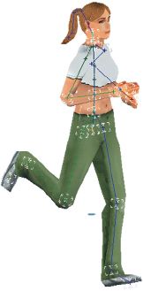
Fig. 2.28 The animation of the bones is transferred to the skin object.
A bones system is a set of non-rendering objects arranged in a hierarchy which reflects the limbs and joints found in a matching character. The bones system can be attached to a mesh object so when the bones are adjusted the mesh is distorted to reflect this. More sophisticated systems allow for realistic flexing of muscles as arms or legs are flexed. This is particularly useful for character animation where the character model may have been created by digitizing a solid 3D object. Bones systems can be used with motion capture data to provide very realistic character movement.
3D MORPHING
With a 3D modeling and animation tool you can arrange for one 3D object to morph into another (called the morph target). There may be a requirement that the original object and morph target have the same number of vertices. The process of morphing causes the vertices of the original shape to move to the positions of matching vertices on the morph target object. The output of this process is a series of in-between 3D objects which can then be viewed in sequence to give the effect of the smooth transition from one shape to the other. Morphing is often used to achieve mouth movement of 3D characters.
PROCEDURAL ANIMATION
Naturally occurring phenomena like smoke and rain are too complex to model manually. Mathematical formulae (also known as procedures) can be used to generate and control many small particles which together give the desired natural effect. Procedural techniques can be used for other complex situations, like the duplication of single characters to create crowds of people or herds of animals that appear to behave in realistic ways.
OUTPUT OPTIONS
The most common type of output format for 3D animation is either as a digital video file or a sequence of bitmap images. The image size can be adjusted depending on whether the sequence is intended for playback on video or television, on film, off computer or via the web.
3D models and animations can also be exported in formats designed for interactive 3D via an appropriate plug-in. These include formats for 3D game engines like Renderware, and formats for web-based interactive 3D like VRML and Macromedia’s Shockwave 3D. There are also plug-ins to convert rendered 3D output into 2D Flash sequences using a cartoon style shader.
VIDEO EDITING AND COMPOSITING TOOLS
There are many occasions when you will need to post-process your animations. You may need to combine your animation with one or more video sequences for some creative multi-layering effect. You might simply need to join parts of a rendered sequence together into a single file. You might need to compress a rendered sequence so that is has a controlled data rate for smooth playback from CD. If you render your animation sequence as a digital video file then it can be treated as any other video sequence in an NLE (Nonlinear editing) tool. You may need to retain an alpha channel in your sequence in order to composite your moving logo over a video background. In this case you might render your animation as a sequence of still images using a file format that supports alpha channels like TGA or PNG. The still image sequence can then be imported into the video editing package and the alpha channel used to composite the 3D animation with other video layers.
DELIVERING ANIMATION
Phew! Now that we have looked at some of the concepts and file formats involved we can start to identify which ones are appropriate for different applications. Linear animation sequences are the staple of video, film and television applications. Much computer delivered animation is linear. Interactive media like multimedia, web pages and computer games may also contain non-linear animation.
Output for video/television
For output to video or television a digital video file or sequence of rendered still images is played back on a video-enabled computer or NLE system and recorded on a video recorder. File formats supported by typical video editing hardware include AVI or Quicktime with the MJPEG codec, which uses lossy spatial compression to achieve any bandwidth reduction. Professional NLE equipment can cope with uncompressed sequences to maximize image quality, amateur equipment may offer a reduced bandwidth and require more compression with a matching reduction in image quality.
Animation sequences featuring rapid movement rendered at 25 f.p.s. (PAL) or 30 f.p.s. (NTSC) and output to video can appear ‘jerky’. This problem can be solved by a technique called field rendering, which takes advantage of the interlaced nature of TV displays. The animation is effectively rendered at 50 f.p.s. (PAL) or 60 f.p.s. (NTSC) and each set of two resulting images are spliced together or interlaced. The subsequent animation appears smoother. Another implication of the interlaced TV display is that you need to avoid thin horizontal lines (1 or 3 pixels high) in your images as these will flicker. For computer display this is not an issue.
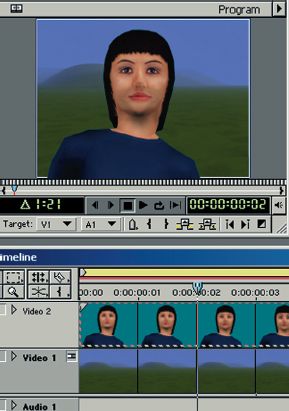
Fig. 2.29 A sequence of rendered images with alpha channels is composited over a video sequence in Adobe Premiere.
Output for film
For film output the frames need to be rendered at a much higher resolution, typically 3000 × 2000 pixels, and output to film via a film recorder. As a result file sizes are much increased.
Playback from computer
Digital video files in AVI, Quicktime (.MOV) or MPG format can be viewed directly on a personal computer. Either you can rely on one of the standard player programs such as Windows Media Player or Apple’s Quicktime player, or else build your animation sequence into a multimedia program.
For playback directly from hard disk the data rate of the sequence needs to be low enough for smooth playback. Typically photorealistic animation files might be rendered at 640 by 480 pixels at 15 f.p.s. Larger image sizes can be tried but you need to test the smoothness of playback. For playback from CD-ROM your digital video sequence would need to have a lower data rate of perhaps 250 kb. This would probably require a smaller image size, possibly 320 by 240 pixels. AVI or Quicktime could be used with either the Cinepak, Indeo or Sorenson codec to achieve the data rate reduction using a mixture of spatial and temporal compression. Your choice of data rate and image size will be influenced strongly by the specification of hardware that you want your animations to play back on.
You might also consider MPEG 1 which delivers 352 by 288 pixels and can give rather fuzzy full screen playback at the very low data rate of 150 kb/s. Some animation packages will render to MPEG directly, others may need to render to an intermediate AVI or Quicktime file and use a stand alone MPEG encoder like the one from Xing software. Professional users might use a hardware MPEG encoding suite to achieve maximum image quality.
Multimedia development tools like Macromedia Director can be used to play back animation sequences stored as digital video files like MPEG, AVI or Quicktime. Director can also be used to present a sequence of still images, or play back a compressed Flash movie.
Pre-rendered animation on the web
Web pages can incorporate pre-rendered animations using file formats including animated GIF, AVI, Quicktime, MPEG, DivX, ASF and Real. Due to the limited bandwidth available to most users of the Internet it is important to keep file size down to the absolute minimum for this purpose. Animated GIFs can be kept small by reducing the number of colours and limiting the number of frames. For the other formats, image sizes are often reduced down to a very small 176 by 144 and large amounts of compression are applied. The files can either be downloaded and played back off-line or streamed: the quality of the experience depends largely on the bandwidth provided by the user’s Internet connection. This may be more satisfactory for users who access the Internet via a corporate network with a relatively high bandwidth. It is more common to use one of the vector animation formats like Flash or Shockwave that require the user’s computer to rebuild the animation sequence from the ‘kit of parts’ that is downloaded.
Real time 3D rendering and computer games
Much 3D computer animation is rendered to image or video files and played back later. This non-real time approach is suitable for sequences that can be designed in advance. For virtual reality and 3D games applications, it is impractical to predict all the different images of a 3D environment that will be needed. Instead, the application must render the scene in real time while the user is interacting. This requires fast modern computer hardware plus real time 3D rendering software like Direct3D and OpenGL where available.
Computer games are usually developed using a programming language like C or C++ in conjunction with a real time 3D rendering API (Application programming interface) such as Direct3D, OpenGL or Renderware. A 3D environment is created in a 3D modeling program like Maya or 3D Max and exported in an appropriate format. The 3D environment is populated with characters and objects. As the user navigates around the 3D environment the rendering engine renders the scene in real time. Animation comes in several forms. Pre-rendered full motion video (FMV) can be added to act as an introduction sequence. Characters or objects can be animated by producing sequences of morph targets. Alternatively, animated bones systems can be defined to distort the skin of a character model. With a fast PC or games console real time 3D engines can process tens of thousands of polygons per second, and although the visual quality of renderings cannot currently match that achieved by non-real time approaches, the gap is closing rapidly.
There are a number of systems offering real time 3D graphics on the web. These include VRML (virtual reality modeling language) which is a text file-based approach to 3D. VRML has been less successful than originally anticipated due to the lack of standard support within browsers. There are a number of proprietary solutions based on Java technology including the one by Cult3D. At the time of writing the approach which seems most likely to become commonplace is Macromedia’s Shockwave3D format. This is a real time 3D rendering system that uses very small compressed files and importantly is supported by the widely installed base of Shockwave browser plug-ins. This technology can be used either simply to play back linear sequences but in a highly compact file format, or alternatively to provide fully interactive 3D applications. The widely used and supported Lingo programming language can be used to control object and camera movements and to detect user interaction with the 3D scene.
CONCLUSION
In this chapter we have looked at some of the jargon of computer graphics and computer animation. We have seen the ways in which animation can be created in 2D and 3D animation packages and looked at the differences between different delivery platforms. In the next chapter we get down to business and start creating a 3D scene.
