
Chapter 3. Selections: The Key to Compositing
I’m fixing a hole where the rain gets in And stops my mind from wandering Where it will go.
–John Lennon and Paul McCartney
A particle physicist works with atoms, bakers and bankers each work with their own types of dough, and compositors work with selections—many different types of selections, potentially thousands, each derived uniquely.
If compositing were simply a question of taking pristine, perfect foreground source A and overlaying it onto perfectly matching background plate B, there would be no compositor in the effects process; an editor could accomplish the job before lunchtime.
Instead, compositors break sequences of images apart and reassemble them, sometimes painstakingly, first as a still frame and then in motion. Often, it is one element, one frame, or one area of a shot that needs special attention. By the clever use of selections, a compositor can save the shot by taking control of it.
This chapter focuses on how a layer merges with those behind it. Then Section II, “Effects Compositing Essentials,” and in particular in Chapters 6 and 7, examines particular ways to refine selections, create high-contrast mattes, and pull keys.
Many Ways to Create Selections
After Effects offers a number of ways to create selections. Here are the most common.
Pull a Matte
Not only keying out the blue or green from an effects film shoot (Figure 3.1), but also high-contrast, or hi-con, mattes, are created by maximizing the contrast of a particular channel or area of the image. Other types of mattes exist as well, such as the elusive difference matte. Chapter 6, “Color Keying,” discusses pulling mattes—the process of creating automated selections using pixel data—in depth.
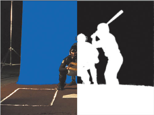
Figure 3.1. This split-screen image shows a blue-screen shoot (left) and the resulting matte. (All baseball images courtesy of Tim Fink Productions.)
Import with Alpha Channel
Alpha and transparency channels are accurate selections that are included for free with computer-generated footage (typically 3D animations, Figure 3.2). They make life easier until you run into problems with alpha channel interpretation, described in Chapter 1, “Compositing in After Effects.” At that point, the fact that After Effects is not explicit about alpha interpretation can actually make life more difficult.
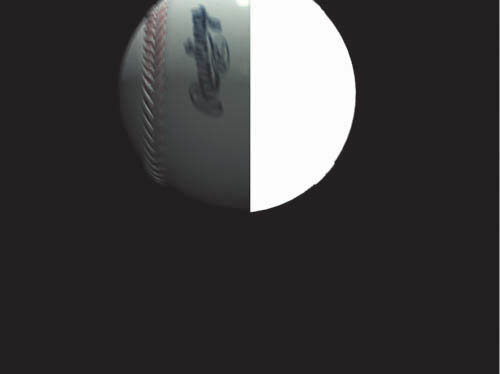
Figure 3.2. A computer-generated baseball’s color and alpha channels.
This is something to watch for not only when you interpret alpha on import but also when applying effects to layers with an alpha. The “Alpha Channels and Premultiplication” section later in this chapter offers the lowdown on how to deal with edge multiplication.
Mask
A mask is a vector shape that determines the opaque and transparent areas of an image (Figure 3.3). This chapter introduces the fundamentals of creating and combining masks. A follow-up discussion in Chapter 7, “Rotoscoping and Paint,” focuses specifically on rotoscoping, the art of animating selections over time.
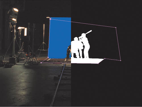
Figure 3.3. This split-screen view shows the garbage matte mask that was added to remove areas of the stage not covered by the blue screen.
Masks are generally created by hand, one vertex at a time, or beginning with a simple primitive shape such as an ellipse. After Effects can also generate them automatically by examining the raster data of an image, using Layer > Auto-trace.
Auto-trace creates detailed and accurate outlines using the contrast of the image, overall or on individual color channels. With all but the very simplest shots, lots of overlapping outlines are created—dozens, typically—too many for effective rotoscoping (Figure 3.4).
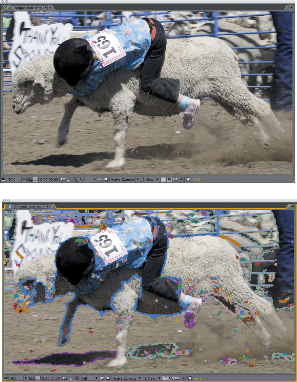
Figure 3.4. The result of Auto-trace on a complex image is interesting but with these settings would likely have only abstract artistic applications.
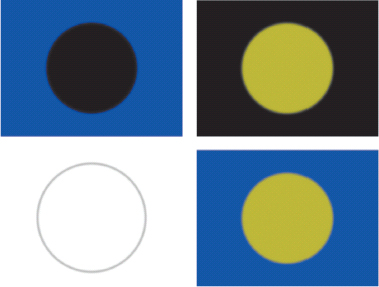
Blending Modes
Blending modes (e.g. Add, Multiply, Screen) combine color channels mathematically, pixel by pixel, in ways that mimic real-world optics (Figure 3.5). Inexperienced compositors will sometimes use selections where blending modes are preferable; expert compositors are good at combining both.
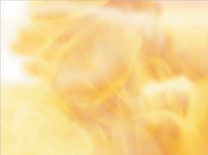
Figure 3.5. Blending modes are the preferred way to composite elements that are composed predominantly of light rather than matter, such as fire.
You can also use selections combined with blending modes to get the best of both worlds.
This chapter focuses in-depth on the modes most relevant to effects compositing and gets into the nitty-gritty of what they are actually doing as they combine pixel data.
Effects
Several effects create or refine transparency selections. Section II explores many of these in detail. Effects such as Levels and Curves include control of the transparency (alpha) channel, and effects in the Channel submenu work with the alpha channel directly.
Combine Techniques
Even an ordinary effects shot will typically combine more than one of the above techniques; for example, you will often apply a garbage matte prior to a color key, or enhance the effect of a blending mode by adding a hi-con matte.
The art is in knowing which approach to apply for a given situation, how to apply it, and when to try something else. No single technique is as sophisticated as the result of combining and refining them together, sometimes in clever and unexpected ways.
Compositing: Science and Nature
What exactly is happening in a simple A over B composite? Is it just like placing one object on top of another, like laying a drawing on your desk? A over B makes intuitive sense, but to master compositing, it helps to know what is going on—not only in the virtual world of software but the physical or “real” world, and beyond that, the equally real physical world of optics.
These three worlds do not always operate according to the same rules, and while it might seem like the digital artist re-creates, as faithfully as possible, what is happening in the natural world, it is the world of optics, the way that the camera sees the world, that a compositor is actually trying to emulate. And edge detail between objects, in particular, distinguishes these worlds rather sharply.
As is detailed further in Chapter 6, the Color Key and Luma Key effects also generate bitmap selections, making them tools largely to be avoided.
Bitmap Alpha
A bitmap selection channel is one in which each pixel is either fully opaque or fully transparent. This is the type of selection generated by the Magic Wand tool in Photoshop. You can feature or blur the resulting edge, but the initial selection contains no semitransparent pixels.
This type of selection may have an occasional use, but it belongs to the world of computers, not nature (or optics). An edge made up of pixels which are either fully opaque or invisible cannot describe a curve or angle smoothly, and even a straight line looks unnatural in a natural image if it completely lacks edge thresholding (Figure 3.6).

Figure 3.6. 400% magnification shows the flaws of a curved or angled shape described by only bitmap pixels, those that are either fully transparent or opaque.
Feathered Alpha
Although it’s easy enough to see that a bitmap edge does not occur in nature, it’s hard to imagine that hard objects should have transparent, feathered edges. Examine the edge of this book. Do you see a soft, semitransparent edge? Of course not.
But now study an image of the same thing, and you’ll find it isn’t razor sharp in its hardness, either. It so happens that semitransparent edge pixels are the digital approximation for overlapping edges in optics because they solve two problems in translating the world of objects to the world of pixels:
• They come closer to describing organic curves (Figure 3.7).

Figure 3.7. Ah—better. Even at 400%, a feathered and antialiased edge more properly describes a smooth, soft curve.
• They mimic optics behavior, the way light and objects interact when viewed through a lens.
The first point is intuitive enough once you’ve gained some experience working with raster images, digital images made up of pixels. The second point is easier to miss.
Study a digital photo with no compositing whatsoever close-up (Figures 3.8a and b). In the digital image, areas at the edge of objects become a fine wash of color combining the foreground and background. This is what happens to light as it travels around objects in the physical world and then through the lens of the camera.
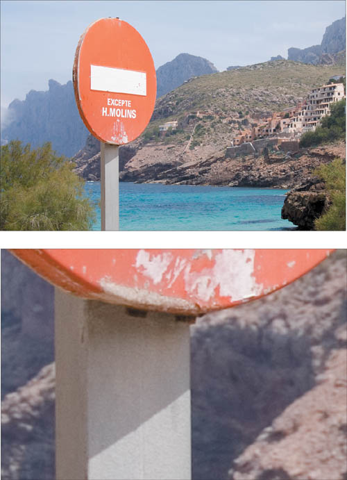
Figures 3.8a and b. This image (a) has no compositing. Natural softness is apparent along hard edges (b) despite that they are in focus.
![]() Close-Up: Geek Alert: The Compositing Formula
Close-Up: Geek Alert: The Compositing Formula
So, what does happen when you layer a raster image with semitransparent alpha over an opaque background image? The foreground pixel values are multiplied by the percentage of transparency, which, if not fully opaque, reduces their value. The background pixels are multiplied by the percentage of opacity (the inverse of opacity), and the two values are added together to produce the composite. Expressed as a formula, it looks like
(Fg * A) + ((1–A)*Bg) = Comp
With real RGB pixel data of R: 185, G: 144, B: 207 in the foreground and R: 80, G: 94, B: 47 in the background, calculating one edge pixel only might look like
[(185, 144, 207) 3 .6] + [.4 3 (80, 94, 47)] = (143, 124, 143)
The result is a weighted blend between the brightness of the foreground and the darker background.
Other effects compositing programs, such as Shake, do not take this operation for granted the way that After Effects and Photoshop do. You can’t simply drag one image over another in a layer stack—you must apply an Over function to create this interaction. Is there a difference? Not until you add to the discussion the operations that go along with an Over, in particular premultiplication, which is detailed later in this chapter.
Opacity
The real world also informs After Effects’ handling of opacity, which can seem illogical, as in the following quiz.
Take two identical layers, no alpha/transparency information for either layer. Set each layer to 50% Opacity, and the result does not add up to 100%. Here’s why.
Zeno’s Paradox goes something like this: Suppose I wish to cross the room. First, of course, I must cover half the distance. Then, I must cover half the remaining distance. Then, I must cover half the remaining distance. Then I must cover half the remaining distance, and so on forever. The consequence is that I can never get to the other side of the room.
A lead developer on the After Effects team once described the program’s opacity calculations as follows: Imagine you have a light which is 1, and place a 50% transparent filter (say, a sheet of vellum) in front of it. Half the total light is permitted through the vellum (0.5 * 1 = 0.5). Put another 50% transparent sheet of vellum on top of that. Now half of half the light shows through (0.5 * 0.5 = 0.25). You can theoretically repeat ad infinitum without reaching 0% light transmission, at least in a pure digital environment.
Hence, and in some tangential relationship to Zeno’s Paradox, After Effects mimics how transparency behaves in the real world. This is not how opacity settings are handled in many alternative compositing applications, and so it often takes users of such programs as Shake by surprise, but the operation is by design.
Alpha Channels and Premultiplication
One major source of confusion and even occasional derision with After Effects has to do with its handling of alpha channels and premultiplication. After Effects has a persistent concept of the alpha channel as part of every image, and this channel is expected always to be un-multiplied within After Effects, whether it originated that way or not. Thus premultiplication is set on import, in the Interpret Footage dialog, and you are more or less expected not to consider edge multiplications until it’s time to render.
This works surprisingly well given the correct import settings, but it doesn’t free you from the need to understand premultiplication and how problems with edges may be related to it.
Premultiplication Illustrated
Premultiplication exists for one reason only: so that rendered images look nice, with realistic, anti-aliased edges against a neutral background, before they are composited.
All premultiplication does is composite the foreground against the background, so that the edges and transparency blend as well into that solid color (typically black) as they would against the final background.
When you ask After Effects to “guess” how to interpret the footage (on import, by choosing Guess in the Interpret Footage dialog, or pressing Ctrl+F/Cmd+F), it looks for repeated pixels indicating a solid color background and the difference between that background color and the foreground in the edge pixels.
What does it mean to have the background multiplied into the edge pixels? Revisit “Geek Alert: The Compositing Formula,” and imagine the background value to be 0,0,0; edge pixels are multiplied by 0 (they turn pure black) and are added to the source, weighted by the percentage of transparency as determined by the corresponding alpha channel pixel. The overall effect is to darken semitransparent edge pixels if the background is black, to lighten them if it’s white, and to really wreak havoc with them if it’s any other color.
The close-ups in Figures 3.9a and b show a section of the same foreground image with the alpha interpreted properly and with it misinterpreted. A misinterpreted alpha either fails to remove the background color from the edge pixels, or removes color that should actually be present.
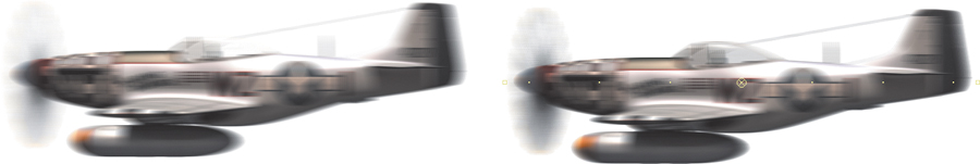
Figures 3.9a and b. Motion blur and a white background clearly reveal improper edge multiplication, especially when compared with the correct version (a). There is dark matting all around the edges, including areas of the canopy meant to be translucent, and around the blur of the propeller (b).
Most computer-generated images are premultiplied, unless specific steps are taken to counteract the process. The Video Output section of the Output Module Settings for items in the Render Queue includes a pulldown to specify whether you render with Straight or Premultiplied alpha; by default, it is set to Premultiplied (Figure 3.10).
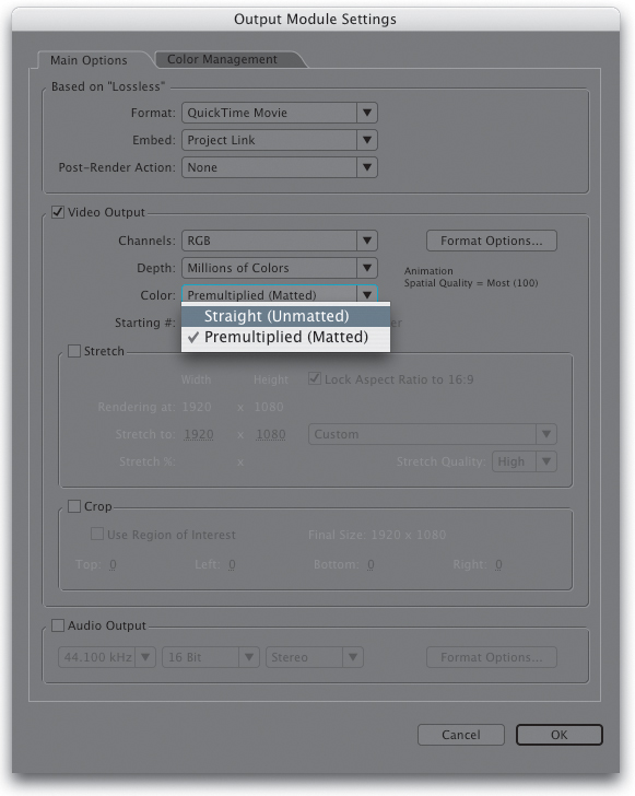
Figure 3.10. Although premultiplied alpha is typically the default setting, the Color pull-down menu in Output Settings can be used to generate straight alphas.
You may find these artifacts presenting themselves although you’ve carefully managed alpha channel interpretation on import; nonetheless, elements have black fringing. Your job depends on getting to the bottom of this. There are two basic ways this can occur:
• An alpha channel is misinterpreted in Interpret Footage (see “Getting It Right on Import”)
• Edge multiplication occurs within a composition, probably unintentionally, by applying a matte and adding a background (see “Solving the Problem Internally”)
Unfortunately, artists who misunderstand the underlying problem will resort to all sorts of strange machinations to fix the black edge, ruining what may be a perfectly accurate edge matte.
Getting It Right on Import
A preference in Preferences > Import determines what happens when footage is imported with an alpha channel; if this is set to anything other than Ask User (the default), you may not know how alpha channels are being interpreted, particularly with the Guess option enabled (Figure 3.11).
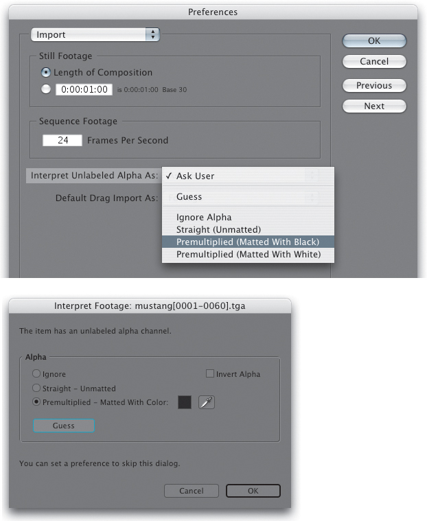
Figures 3.11a and 3.11b. Import preferences default to Ask User about alpha channel interpretation (a); this presents the Interpret Footage dialog (b) which includes a button marked Guess that will typically get the setting right, or generate a beep in cases of uncertainty.
To see any alpha channel displayed in straight alpha mode (all pixels with any transparency displaying as pure white), choose RGB Straight from the Show Channel pull-down menu, below the Composition and Layer panels (Alt+Shift+4/Option+Shift+4).
Guess can be wrong if the factors it expects in a premultiplied alpha are there in a straight image or vice versa. Thus it is preferable not to trust to automation.
With a premultiplied image, After Effects attempts to guess not only the setting but also the color of the background; generally this will be black or white, but watch out for situations where a 3D artist has become creative and rendered against canary yellow or powder blue. For that reason, there is an eyedropper adjacent to the Matted with Color setting (Figure 3.11).
When in doubt, examine your footage without the alpha applied: If you see a solid background that is neither pure black nor white and After Effects isn’t detecting it, use the eyedropper.
Fundamentally, though, as an effects compositor you need to be able to examine your images and spot the symptoms of a misinterpreted alpha: dark or bright fringing in the semi-opaque edges of your foreground.
Remove Color Matting will not work properly on a layer with a track matte; be sure to precompose the layer and its track matte prior to applying Channel > Remove Color Matting.
Solving the Problem Internally
The really gnarly fact is that premultiplication errors can be introduced within a composition, typically by applying a matte to footage that is already somehow blended—multiplied—with a background.
UnMult, originally created by John Knoll and available free from Red Giant Software (and included on this book’s disc), is useful in tricky situations in which Remove Color Matting won’t do the job because there is no alpha channel. It uses the black areas of the images to create transparency and remove premultiplied black from the resulting transparent pixels.
If you see fringing in your edges, you can try the Remove Color Matting effect (Figures 3.12a and b). This effect has one setting only, for background color, because all it does is apply the unpremultiply calculation (the antidote to premultiplication) in the same manner that it would be applied in Interpret Footage.
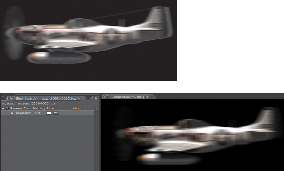
Figures 3.12a and b. The plane was matted against a white background, but transparency has been applied via a track matte (the equivalent of a straight alpha), so white fringing appears against black (a). Remove Color Matting with Color set to pure white corrects the problem (b), but only when applied to a precomp of the image and matte.
Masks
Although hand-created and animated for the most part, masks open up all kinds of possibilities in After Effects. Masks are the principal method for defining transparency regions in a clip without regard to actual pixels because they are vector shapes. This section lays down the basics for smart use of masks.
Shape layers are a new addition to After Effects CS3. These are directly related to masks; they are drawn with the same tools (Figure 3.13). Generally, if a selected layer can receive a mask, then After Effects draws a mask by default; otherwise, it creates a new Shape layer, generally to serve as a design element in a motion graphics project, rather than to define transparency, although it can be used as a track matte. More about Shape layers is found below.
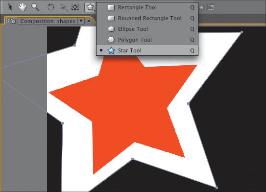
Figure 3.13. If an image is selected in the Timeline, selecting a shape tool in the toolbar and dragging in the viewer creates a mask (and so there are five basic mask shapes where previously there were two); otherwise, a new Shape layer is added with its own properties.
Typical Mask Workflow
Masks are the principal non-procedural method to define transparency in a layer, using vector shapes. There are five basic automated shapes and the Pen tool (G) for drawing free-form. The Q key activates and then cycles through the basic mask shapes.
A mask can be drawn in either the Composition or Layer viewer. Layer makes it easier to draw while continuing to look at the source; you can toggle Render with Masks Selected in the pull-down menu to disable all mask selections (Figure 3.14). Composition allows you to see the layer in context, but if a layer is, for example, rotated in 3D space, it can be difficult to draw or adjust a mask; an ideal compromise in such cases is to open the Layer and Composition views side-by-side.
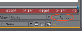
Figure 3.14. Use this toggle in the Layer viewer to disable a mask; as long as it’s selected, it’s still visible.
When drawing with a mask tool
• Double-click the Mask tool (in the Tools palette) to set the boundaries of the mask shape to match those of the layer.
Even if your mask can’t be completed with one of the five preset shapes, it can be helpful to use them as a starter and then edit with the Pen tool if they are anything like what you’re trying to draw.
• Use Shift to constrain the shape; Ctrl/Cmd draws the shape from the center.
• The Mask Shape dialog is useful in rare cases where your mask requires exact dimensions. Access it by clicking the underlined word “Shape” under Mask options (M with the layer highlighted).
• Double-click the shape itself to activate Free Transform mode, which enables you to offset, rotate, or scale the entire mask shape (Figure 3.15). As always, hold down Shift to keep the scale proportional, snap the rotation to 45-degree increments, or constrain movement to one axis.
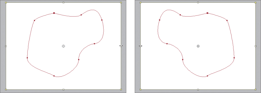
Figure 3.15. How do you flip a mask symmetrically in After Effects? Enable View > Show Grid and View Snap to Grid, then double-click the Rectangular Mask tool to create a second mask that is the exact size of the layer. Select both masks, then double-click a point to set the Free Transform tool. Now drag the handles at the image boundaries to the opposite sides, deleting the layer-sized mask when you’re done.
• Highlighting a layer with a mask and pressing MM (the M key twice in rapid succession) reveals the full Mask options for that layer.
• Feather is applied to the entire mask, and is always centered around the mask path (half the amount of feather is applied inside and outside the mask). Big, soft masks are useful for all kinds of lighting, smoke, and glow effects, detailed throughout this book (Figure 3.16).
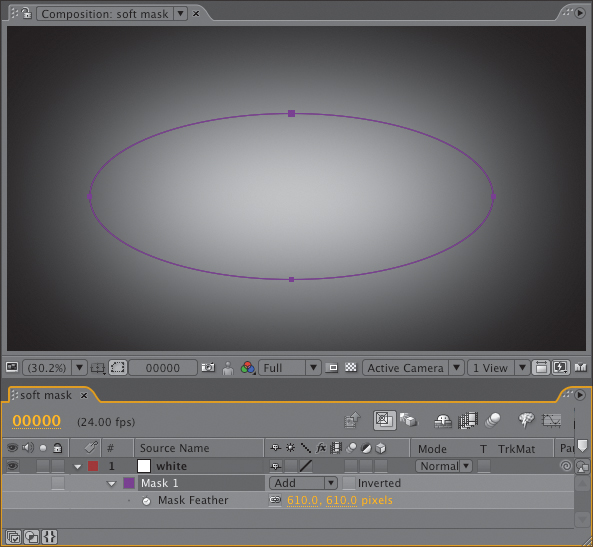
Figure 3.16. The Feather of this mask is set roughly equal to its radius, creating a big, diffuse gradient in the shape of the mask (in this case, elliptical), useful for many types of lighting effects.
• Press the F key to solo the Mask Feather property.
• Mask Expansion expands or (given a negative value) contracts the mask area, often a preferable alternative to redrawing a mask.
The Mask Expansion feature has many uses; you can, for example, create an edge selection with boundaries of your choice. Expand a mask, duplicate it, and set the duplicate to Subtract with a negative Mask Expansion value.
Keyboard shortcuts help eliminate a lot of the fuss and bother that comes with masking in After Effects.
Bézier Masks
By default, the Pen tool creates Bézier shapes; learn the keyboard shortcuts and you can fully edit a mask without ever clicking anywhere except right on the mask.
I sometimes draw a Bézier mask first as straight lines only, clicking to place points at key transitions and corners. Once I’ve completed the basic shape, with the Pen tool still active, I can go back point-by-point and edit the shape, because I have instant access to all of the mask shortcuts shown in the Pen Tool pulldown:
• Click on a point with the Pen tool active to delete it (look for the minus “-” sign in the cursor).
• Click on a segment between points with the Pen tool active to add a point (a plus sign in the cursor).
• Alt/Option-click on a point with the Pen tool to enable the Convert Vertex tool (which looks like a caret): Apply it to a point with no handles, and you can drag out to create handles. Apply it to a point with handles, and you cancel the handles.
• Click on a Bézier handle with the Pen tool to break the center point of the Bézier, enabling you to adjust the handles individually.
• Context-click on the mask path to enable the context menu of options for that mask, including Mask settings found in the Timeline, the ability to specify a First Vertex (detailed below), and Motion Blur settings for the mask, which can be toggled on or off separate from the layer itself.
• Hold down Ctrl/Cmd to enable the Selection tool, then double-click the shape to activate free transform. Alternatively, you can always switch to the Selection tool by pressing V. The G and V keys enable the Pen and Selection tools, respectively, at any time.
• Click on a point with the Pen tool active to delete it (look for the minus “=” sign in the cursor).
• To deselect the current mask and start a new one without switching tools, use F2 or Ctrl+Shift+A (Cmd+Shift+A) to deselect the active mask.
Standard in all Adobe mask tools, including After Effects: as you draw a mask, to move a vertex into exact place after drawing it, keep the mouse button down and hold the spacebar; you can freely move the vertex until you release the spacebar, and if the mouse is still held you can drag out tangent handles. Toggle between the two modes as often as necessary.
Shape Layers
Because the focus of this book is realistic visual effects more than abstract motion graphics, the Shape tools don’t get as much attention here as they might in a book that assumed you to be a visual designer rather than an effects artist. Like the Type tools, Shape isn’t essential to effects work, where masks are the bread and butter.
However, if you fully understand what makes a Shape layer unique from a masked solid, it may help you discover creative uses for it (and in any case, most of us actually fall somewhere on the spectrum between pure realism and abstraction in our work). Try creating some shapes, then create a solid and with it selected, try selecting the same shapes as masks for that solid. Here’s what you discover:
• There are five basic shapes, equally available as Shape layers or mask paths, with a key difference: when you create a Star, Polygon, or Rounded Rectangle as a mask its vertices can be edited as normal Béziers. A shape’s points cannot themselves be edited; instead, you edit the entire shape either by adjusting existing properties in the Timeline or by adding new ones—some of which, such as Pucker & Bloat, Twist, or Zig Zag, will deform the entire shape.
• Shapes all have two basic characteristics: Fill and Stroke, each optional and editable. With a Shape active, Alt/Option-click on Fill and Stroke in the toolbar to cycle through the options (also available in the Timeline).
• Shapes can be instanced and repeated in 2D space.
The last point may be the most significant: Consider shapes when you need a repeatable pattern of some type, such as the film sprockets in Figure 3.17. You could create something like this using masks as well, but a Shape layer has the advantage of letting you edit a single set of parameters and apply it to the entire pattern. There is no 3D repeat option—that will have to wait for a future version of the software.
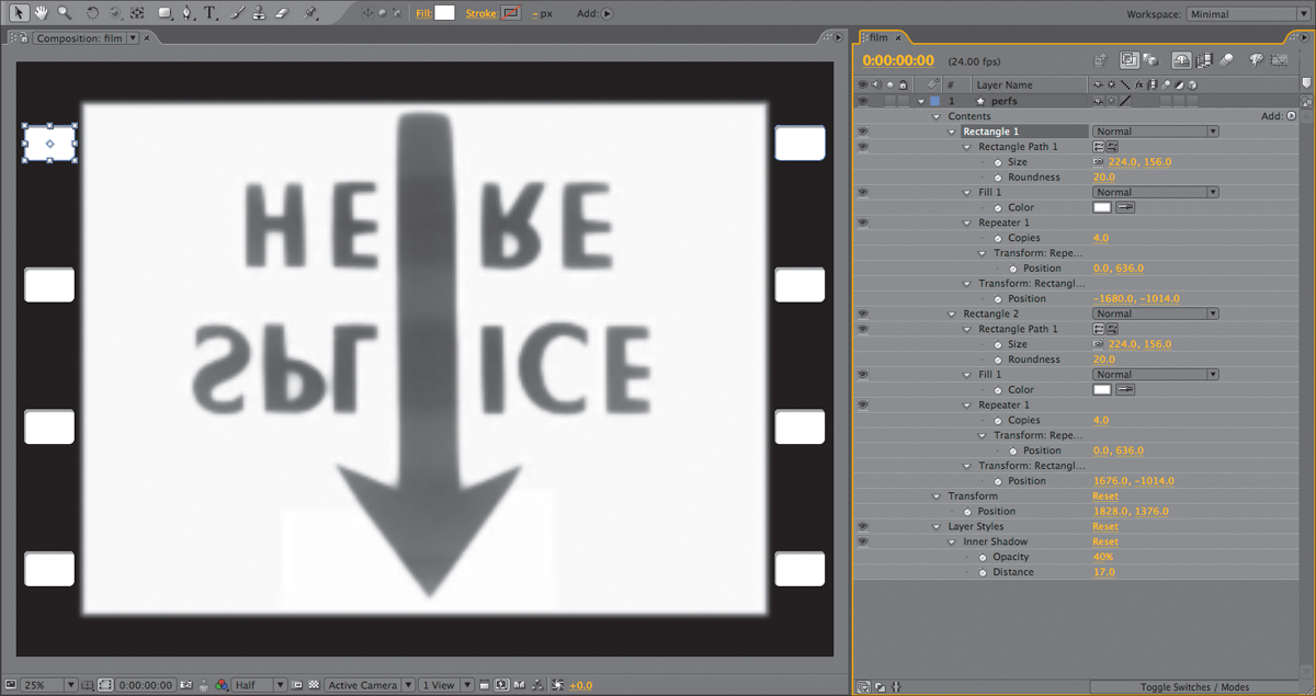
Figure 3.17. It’s easy to create a repeatable pattern such as these film sprocket holes using a shape and the Repeater property, although it results in a lot of editable properties that can appear confusing. Here I’ve even added an Inner Shadow Layer Style to give a little feeling of depth and dimension.
Combining Multiple Masks
By default, all masks are drawn in Add mode, meaning that the contents of the mask are added to the layer selection, and the area outside all of the masks is excluded. There are other options for combining them, however; the five primary mask modes are
• Add: The default mode; adds the opacity values to the image as a whole, including masks higher in the stack (Figure 3.18).
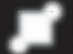
Figure 3.18. Add mode combines the luminance values of overlapping masks.
• Subtract: Subtracts opacity values from areas which overlap with masks higher in the stack or from the image as a whole if no other masks precede it (Figure 3.19).
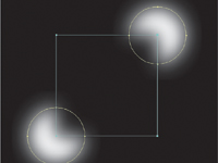
Figure 3.19. Subtract mode is the inverse of Add mode.
• Intersect: Combines only the areas of opacity that overlap (intersect), with masks higher in the stack (Figure 3.20).

Figure 3.20. Intersect mode adds only the overlapping areas of opacity.
• Difference: Subtracts overlapping areas (Figure 3.21).
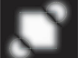
Figure 3.21. The inverse of Intersect, Difference mode subtracts overlapping areas.
• None: Has no effect on the image whatsoever; this is like turning off or disabling the mask. It can be useful as a placeholder or for effects that use masks (Figure 3.22).
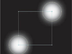
Figure 3.22. With None mode, the mask is effectively deactivated.
In Preferences > User Interface Colors, enable Cycle Mask Colors and each new mask you create automatically uses the next color of the 16 listed in Preferences > Label Colors (which you can also customize). It’s much easier to work with several masks on one layer when they’re not all yellow.
Two variables change the above mask interactions in somewhat mind-bending ways. A toggle labeled Inverted sits adjacent to the mask mode pull-down menu. Inverting an Add mask is straightforward enough; all of the areas outside the mask are selected, instead of those inside. The Mask Opacity property (revealed by twirling open the mask) lets you dial back the strength of a mask; setting any mask other than the first one to 0% is like disabling it.
The behavior of Mask Opacity works a little differently for the first mask. A single Add mask set to 0% Mask Opacity causes the entire layer to disappear. That’s logical, because otherwise setting that mask to, say, 50% would have to cause 50% of the area outside the mask to reappear. However, if the first mask is set to Subtract, setting Mask Opacity to 50% does just that—instead of the area inside the mask reappearing, the rest of the scene becomes 50% transparent. I call this a bug, and the development team has acknowledged that it only stays this way for backward compatibility; the workaround is to start with a full-frame mask set to Add mode, then add a Subtract mask. Generally speaking, it’s easier to understand masks if the first mask is set to Add, whether it is inverted or not.
When rotoscoping (masking an animated shape, detailed in Chapter 7) it is wise to employ multiple masks, as attempting to animate a complex shape that does not move in a single direction can become cumbersome, or even impossible.
Overlapping Transparency
“Density” is traditionally a film term describing how dark (opaque) the frame of film is at a given area of the image. It is therefore the inversion of opacity or alpha values; the higher the density, the less light is transmitted. In the digital world we sometimes speak of masks and alpha channels as having “density,” and overlapping semitransparent areas must be managed to avoid having the densities build up in undesirable ways.
Trouble keeping multiple masks organized? Name them in the Timeline (Return key, then type), change the color if it could be more visible, and lock masks you’re not using. You can even context-click on the mask you’re editing and choose Mask > Lock Other Masks, and if overlapping masks are still too much in your way, Mask > Hide Locked Masks.
When combining masks that have semitransparent areas, either because the opacity of the masks is less than 100% or, as in the examples shown here, because the edges are heavily feathered, two overlapping pixels each with 50% transparency would become fully opaque, not usually the desired behavior. That’s when Lighten and Darken modes come into play.
Figures 3.23a and b show the result of using each of these modes; they prevent mask densities from building up the way that they do with the other modes. No pixel within the combined masks will have a value greater or lesser than the same pixel in the overlapping masks; either the lighter or the darker of the two will be represented.
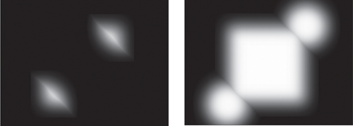
Figures 3.23a and b. A Darken (a) or Lighten (b) mask uses only the darker (lower) or lighter (higher) value, respectively, for overlapping pixels.
Remember that masks render from top to bottom, so each mask’s mode applies to its relationship with the layers above it. Thus applying these modes to the top mask in the stack has no effect.
Masks in Motion
Ahead of Chapter 7’s more detailed discussion of rotoscoping, here are the basics to put a mask in motion.
Interpolation Basics
You can set a temporal ease on a mask keyframe (and adjust it in the Graph Editor), but there is no corresponding spatial curve to adjust, as there is with Position keyframes. Each point will travel in a linear fashion to its next keyframed position. Thus in order to precisely mask an object traveling in an arc, you must set many more keyframes than for an object traveling in a single direction.
Despite that After Effects now lets you apply expressions to a mask (see Chapters 7 and 10 for more on this), there’s no way to get at the translation data of the mask points directly, and thus you can’t translate a group of mask keyframes together. As soon as you move, rotate, or scale it, your selection snaps to the current keyframe only.
You can instead duplicate the layer being masked and use it as an alpha track matte for an unmasked source of the same layer, in which case you’re free to transform (or even motion track) the duplicate using the normal layer transforms. This may seem like a less-than-perfect solution, but Chapter 7 elucidates how working this way can also make rotoscoping in After Effects much faster and more efficient.
Moving, Copying, Pasting, and Masks
You can freely copy a mask path from one source (a different mask, a different keyframe in the same mask animation, or even another Adobe application that uses mask paths such as Illustrator, or Photoshop) and paste it into an existing Mask Path channel, but beware of the following situational rules:
• With no Mask Path keyframes in the source or target: Copying the mask and pasting it to another layer automatically either creates a new mask, or applies it to any mask that is selected.
• Source mask contains Mask Path keyframes, target has none: Highlighting the mask (not the specific keyframes) and pasting creates a new mask as if pasting from time 0. Highlighting any or all Mask Path keyframes pastes a new mask with keyframes starting at the current time.
• Target layer contains masks (with or without keyframes): To paste Mask Path keyframes into a particular mask at a particular time, highlight the target mask before pasting. Highlighting the target Mask Path property highlights any keyframes and replaces them, effectively deleting the previous shape.
If the target layer has different dimensions than the source, a mask stretches to maintain its relationship to the boundaries of that layer when copied and pasted. This is an advantage when the target is different sized but identically proportioned.
When you need to replace a specific mask path at a specific keyframe, there is a somewhat hidden feature in the Layer panel to make it less of a blind operation than the final option above. The Target pulldown along the bottom of the window lets you choose an existing mask as the target; you can start drawing a new mask anywhere in the frame and it replaces the shape in the target mask layer (Figure 3.24).
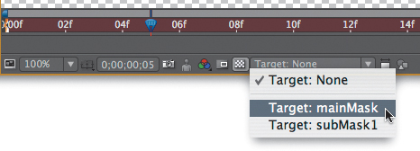
Figure 3.24. This pull-down menu along the bottom of the Layer panel makes it easy to create a new mask path that replaces the shape in the target mask. If the target mask has keyframes, After Effects creates a new keyframe wherever the new shape is drawn.
Smart Mask Interpolation (available via a panel in the Window menu) is designed to help you transition between two radically different shapes. It’s not too essential to normal masking and rotoscoping, but if you’re ever out of luck with normal mask vertex interpolation, you could check it out, with the help of the online documentation.
First Vertex
When pasting in shapes or radically changing the existing mask by adding and deleting points, you may run into difficulty lining up the points. Hidden away in the Layer > Mask (or Mask context) menu, and available only with a single vertex of the mask selected, is the Set First Vertex command. If your mask points twist around to the wrong point during an interpolation, setting the First Vertex to two points that definitely correspond should help straighten things out. This also can be imperative for effects that rely on mask shapes, such as the Reshape tool (described in Chapter 7).
Traditional optical compositing—covering all movies made prior to the 1990s—was capable of bipacking (multiplying) and double-exposing (adding) two source frames (layers). Many sophisticated effects films were completed using only these two “blending modes.”
Blending Modes: Compositing Beyond Selections
After Effects includes 34 blending modes, each created with a specific purpose (Figure 3.25)—although no one is quite sure in what context Dancing Dissolve was ever useful (and I’m only half joking). For effects work, moreover, the majority of them are not particularly recommended.
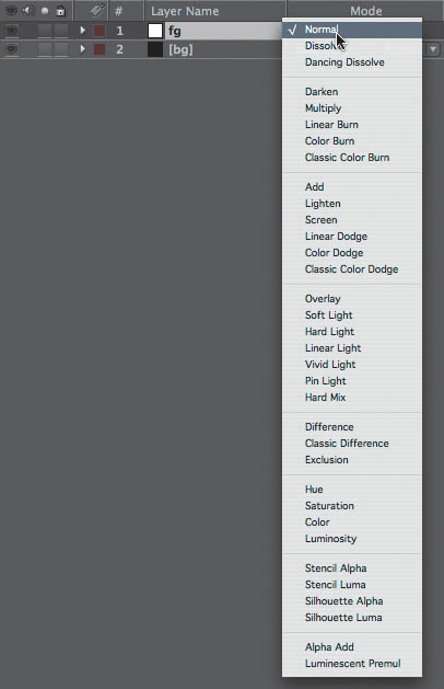
Figure 3.25. With 34 blending modes to choose from, it’s virtually guaranteed that less experienced users will be easily overwhelmed and compelled to play hunt and peck. You will likely use a small subset of these 90% of the time.
So how do you tell which are the useful ones? Once you understand how your options work, you can make informed compositing decisions instead of relying on trial and error.
These mathematical descriptions of blended pixel values use a color range normalized to 1; in other words, the full range of pixel values is described as 0 to 1 instead of 0 to 255, as it typically appears in your color controls. A medium gray on any channel is 0.5 instead of 128, pure white is 1, and pure black is 0 (Figure 3.26). This makes it much simpler to show the calculations that are actually used to create the blended pixels, because the internal math typically is based this way. For information about overbright values, which have a value greater than 1, see Chapter 11, “32 Bit HDR Compositing and Color Management.”
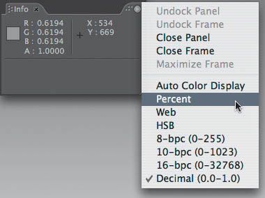
Figure 3.26. The Info panel can display pixel values in several optional modes (accessed via the panel menu). Shown here are decimal values with the cursor on medium gray. Visible decimal values are “normalized” to the range of 0.0 to 1.0, which makes calculations more straightforward than 0 to 255, the standard 8-bit range (or the even more obtuse 0 to 32768 for 16-bit). Select a color mode for the Info palette via its wing menu; whatever mode you select is thereafter also used by the Adobe Color Picker.
Blending modes are all based on mathematical operations for combining pixels in the layer containing the given blending mode and the pixels behind it—either below it in the stack, if all the layers are 2D, or positioned behind it in 3D space, if all the layers are 3D.
To help you understand what the various blending modes are doing, Figures 3.27 through 3.33 blend a grayscale gradient over a fully saturated background. Contextual examples using these blending modes follow in the next section.

Figure 3.27. Blending in this figure is set to Normal for purposes of comparison with those that follow.
Add and Screen
Add and Screen modes both brighten the foreground image while making darker pixels transparent. Screen yields a subtler blend than Add in normal video color space, but does not work correctly with linear color (details in Chapter 11).
Add mode is every bit as simple as it sounds; the formula is
newPixel = A + B
where A is a pixel from the foreground layer and B is a background pixel. The result is clipped at 1 for 8- and 16-bit pixels.
Add is incredibly useful with what After Effects calls a Linearized Working Space, where it perfectly re-creates the optical effect of combining light values from two images. It is useful for laying fire and explosion elements shot in negative space (against black) into a scene, adding noise or grain to an element, or any other element that is made up of light and texture (Figures 3.28a, b, c, and d).
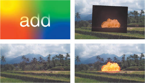
Figures 3.28a, b, c and d. Add mode (a) takes the source foreground element, the fire shot against a black background (b), and adds its pixel values channel by channel to the background (c), causing the pure black pixels to disappear completely (d).
Linear Dodge and Add are identical blending modes; the former is merely Photoshop’s term for the latter.
Screen mode has an influence similar to Add mode’s, but via a slightly different formula. The pixel values are inverted, multiplied together, and the result is inverted:
newPixel = 1–((1–A) * (1–B))
In Screen mode, fully white pixels stay white, fully black pixels stay black, but a midrange pixel (0.5) takes on a brighter value (0.75), just not as bright as would be with Add (1).
Once you discover the truth about working linearized with a 1.0 gamma, you understand that Screen is a workaround, a compromise for how colors blend in normal video space. Screen is most useful in situations where Add would blow out the highlights too much—glints, flares, glow passes, and so on (Figure 3.29).

Figure 3.29. The difference between Screen and Add (Figure 3.28) may be subtle in printed figures until you look closely; notice there’s less brightness in the “hottest” areas of the fire.
Multiply
Multiply is another mode whose math is as elementary as it sounds; it uses the formula
newPixel = A * B
To fully comprehend the difference between Add and Screen requires an understanding of a linearized working space, which is offered in Chapter 11.
Keep in mind that this formula uses color values between 0 and 1 to correspond to the colors on your monitor. Multiplying two images together, therefore, actually has the effect of reducing midrange pixels and darkening an image overall, although pixels that are full white in both images remain full white.
Multiply or Add has the inverse effect of Screen mode, darkening the midrange values of one image with another. It emphasizes dark tones in the foreground without replacing the lighter tones in the background, useful to create for texture, shadow, or dark fog (Figure 3.30).

Figure 3.30. Dark smoke (actually a grayscale fractal noise pattern) is multiplied over the background, darkening the areas that are dark in either the foreground or background further.
Overlay and the Light Modes
Overlay uses Screen or Multiply, depending on the background pixel value. Above a threshold of 50% gray (or .5 in normalized terms), Screen occurs, and below the threshold, Multiply. Hard Light operates similarly, instead using the top layer to determine whether to screen or multiply, so the two are inverse effects.
Overlay and the various Light modes do not work properly with values above 1.0, as can occur in 32 bpc linearized working spaces (see Chapter 11).
These modes, along with Linear and Vivid Light, can be most useful for combining a layer that is predominantly color with another layer that is predominantly luminance, or contrast detail (Figure 3.31). Much of the lava texturing in the Level 4 sequence of Spy Kids 3-D was created by using Hard Light to combine a hand-painted color heat map with moving fractal noise patterns.

Figure 3.31. Overlay and its inverse, Hard Light, are useful for combining color and texture. Here, an instant lava lamp texture was created using the components shown at the right: a solid with Fractal Noise applied set to Overlay mode on top of a red-to-yellow gradient.
Difference
Difference inverts a background pixel in proportion to the foreground pixel. It can help you line up two identical layers, which is helpful while working even if you rarely use it for final output (Figure 3.32).
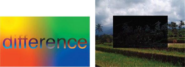
Figure 3.32. The selection area in the foreground is identical to the background; when they are perfectly aligned, all pixels cancel out to black.
HSB and Color Modes
The Hue, Saturation, and Brightness modes each combine one of these values (H, S, or B) from the foreground layer with the other two from the background layer. Color takes both the hue and saturation from the top layer, using only the luminance (or brightness of) from the underlying background (Figure 3.33).
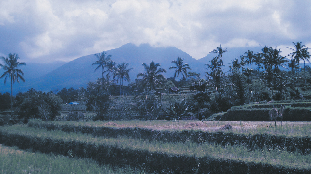
Figure 3.33. Setting a deep-blue-colored solid to Color mode and overlaying it on the plate footage has the effect of tinting the colors in the image blue. Artistic uses of this mode are explored in Chapter 12, “Light.”
These modes are often useful at an Opacity setting below 100%, to combine source HSB values with ones that you choose.
Stencil Alpha and Silhouette Alpha are useful to create custom edge mattes as well as a light wrap effect, demonstrated in Chapter 12.
Stencil, Silhouette, Preserve Transparency
Commonly overlooked, Stencil and Silhouette blending modes operate only on the alpha channel of the composition. The layer’s alpha or luminance values become a matte for all layers below it in the stack. Stencil makes the brightest pixels opaque, and Silhouette the darkest.
Suppose instead you have a foreground layer that is meant to be opaque only where the underlying layers are opaque, as in Figure 3.34. The small highlighted checkbox, labeled Preserve Underlying Transparency, makes this happen, much to the amazement of many who’ve wished for this feature and not realized it was already there.
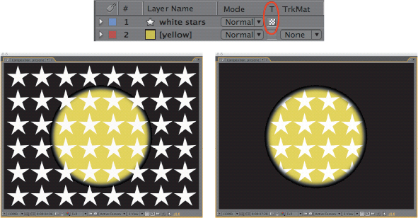
Figure 3.34. Among the hardest-to-find and most-easily-forgotten features in the Timeline is the Preserve Underlying Transparency toggle, highlighted. This recreates behavior familiar to Photoshop users, where a layer’s own transparency only applies where it intersects with that of the underlying layer, one more way to avoid track mattes or precomping.
Alpha Add and Luminescent Premultiply
Alpha Add and Luminescent Premultiply are blending modes that affect semitransparent edge pixels only.
Just as two overlapping layers with 50% opacity are not fully opaque when layered together (see “Opacity”), the same behavior applies to semitransparent pixels. Just as the name implies, Alpha Add directly adds transparency pixels, so, for example, two 50% opaque pixels combine to become 100% opaque (Figures 3.35a through d).
Figures 3.35a through d. It seems as though matting an object over another with the exact inverse matte (a, b) would result in a fully opaque image. Instead, edge pixels form a semitransparent halo (c). Alpha Add does just what the title implies, adding the alpha values together so that inverse pixels add up to 100% transparency throughout the image (d).
Why would you combine a layer with itself, inverting the alpha? You probably wouldn’t. But you might combine two layers with overlapping transparency that would require this method—for example, two parts of the same layer.
Luminescent Premultiply is one method to remove premultiplication on the fly from source footage, retaining bright values in edge pixels that are otherwise clipped. Premultiplication over black causes all semitransparent pixels to become darker; removing it can cause them to appear dimmer than they should.
Luminescent premultiply can be useful in cases where an element with transparency has been created against a black background within After Effects, bypassing the opportunity to remove premultiplication on import.
Track Mattes
Track mattes allow you to use the alpha or luminance information of one layer as the transparency of another layer (Figure 3.36). It’s a simple enough concept, yet one that is absolutely fundamental as a problem-solving tool for complex composites.
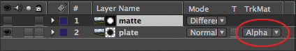
Figure 3.36. The alpha of layer 1 is set as the alpha of layer 2 via the highlighted pull-down menu. The small icons to the left indicate which is the image and which is the matte.
The perceptual difference between an alpha channel and a track matte isn’t, for the most part, too difficult to grasp. In both cases, you have pixels with a value (in 8-bit color space) between 0 and 255, whether a grayscale alpha channel or three channels of color. With color, the three channels are simply averaged together to make up a single grayscale alpha. With 16 and even 32 bpc, it’s finer increments in the same range.
Node-based compositing programs all make it possible for a single node to provide transparency to as many others as is needed. After Effects also has a one-to-many capacity, but it generally means precomping and reusing the nested composition in several places. The point here is that in After Effects, each track matte needs to be a layer in the composition. To share it dynamically among several layers—allowing you to change the matte and have the change affect them all the same way—requires either that the matte be precomposed and all the changes made in the precomp, or that you use expressions to link essential properties together (this being the more complicated and limited approach, but one that avoids precomping).
To set a track matte, place the layer that contains the transparency data directly above its target layer in the Timeline and choose one of the four options from the Track Matte pull-down menu:
• Alpha Matte: Uses the alpha channel of the track matte layer as if it were the alpha of the underlying target layer
• Alpha Inverted Matte: Does the same as Alpha Matte but inverts the result, so that the lighter areas of the alpha are transparent and the darker areas are opaque
• Luma Matte: Uses the luminance data of the track matte layer (the relative brightness of the red, green, and blue channels combined) as if it were the alpha of the underlying target layer
• Luma Inverted Matte: Does the same as Luma Matte but inverts the result, so that the lighter areas of the alpha are transparent and the darker areas are opaque
By default, visibility of the track matte layer is disabled when you activate it from the layer below by choosing one of these four modes, which is generally desirable. Some clever uses of track mattes leave them on; for example, by matting out the bright areas of the image and turning on the matte, setting it to Add mode, you could naturally brighten those areas even more.
Track mattes solve a lot of compositing problems. They also help overcome limitations of After Effects. For example, it’s not possible to track a mask in After Effects. But it is possible to apply the mask to a track matte instead, and then to track that layer (instead of the mask itself). Chapter 8, “Effective Motion Tracking,” discusses this in detail; it can change rotoscoping in After Effects from nearly impossible to easy. Any procedural matte that you create using techniques described in Chapter 6 can be applied as a track matte rather than directly on a layer; this allows you, for example, to create a matte with Keylight without having it change the color of the matted layer.
Gotchas
Even an advanced user has to pay attention when working in a composition with track mattes. They are exceptional in certain ways that can bite you. Unlike parented layers, track mattes do not stay connected with their target if moved around; instead, if you move a layer that has a track matte set to it without moving the matte along with it, the layer will use whatever layer is above it. Move it to the top of the composition and it will use no track matte until you add another image above it, but at that point you may have forgotten all about having applied the track matte in the first place.
If the layer to which the track matte is applied already has an alpha channel, then the new selection area created by the track matte is opaque only in the areas that intersect.
After Effects does at least help you in certain ways. Duplicate a layer (Ctrl+D/Cmd+D) with a track matte activated and it moves up two layers, above the track matte layer. Include the track matte when you duplicate and it also moves up two layers, so layer order is preserved (Figure 3.37).
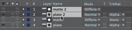
Figure 3.37. Select and duplicate the layers from Figure 3.41, and the two new layers leapfrog above to maintain the proper image/matte relationship.
Render Order
Render order when using track mattes can be tricky. In most cases, adjustments and effects that you apply to the matte layer are calculated prior to creating the target matte, but in other cases you must first precompose for applied effects and adjustments to activate prior to application of the track matte.
If there seems to be some doubt as to whether edits you are applying to the track matte are properly affecting the target, be scientific about it. First crank up the effect applied to the track matte, so it’s obvious whether it is applied or not. If it’s not, you must precompose the track matte layer; this forces it to render prior to track matting.
And what happens when you apply a track matte to another track matte? Generally speaking, this will not work and the practice should be avoided. It will work in some cases, however, and the user interface does not prohibit doing so. A better idea is certainly to precompose the first instance of track matting and apply the second track matte to that nested composition.
The next chapter looks in depth at solving issues related to render order such as these; you’ll begin to see how to use the Timeline as a visual problem-solving tool for such situations.