
Electrochemical cells
Chemical cells and batteries
Chemical cells were the original source of DC, and have always been an important form of power supply for electronic equipment. Historically, cells and batteries have been in use for over two hundred years, and the problems that are encountered with one of the simplest and oldest types of cell are a good introduction to the reasons why so many diverse battery types exist nowadays, and to the technology that is used. Strictly speaking, a battery is an assembly of single cells, so that the action of a cell is the subject of this chapter.
Any type of chemical cell depends on a chemical action which is usually between a solid (the cathode plate) and a liquid, the electrolyte. The use of liquids makes cells less portable, and the trend for many years has been to use jellified liquids, and also materials that are not strong acids or alkalis. The voltage that is obtained from any cell depends on the amount of energy liberated in the chemical reaction, but only a limited number of chemical reactions can be used in this way, and for most of them, the energy that is liberated corresponds to a voltage of between 0.8 and 2.3 V per cell with one notable exception, the lithium cell. This range of voltage represents a fundamental chemical action that cannot be circumvented by refining the mechanical or electrical design of the cell.
The current that can be obtained from a cell is, by contrast, determined by the area of the conducting plates and the resistance of the electrolyte material, so that there is a relationship between physical size and current capability. The limit to this is purely practical, because if the cell is being used for a portable piece of equipment, a very large cell makes the equipment less portable and therefore less useful. Hundreds of types of cells have been invented and constructed since 1790, and most of them have been forgotten, even from school textbooks (although the Weston Standard Cell still occupies a place despite the fact that the more practical mercury button cell, bought from the local chemist at a tenth of the price, provides as useful a reference voltage). By the middle of the twentieth century, only one type of cell was commonly available, the Leclanché cell which is the familiar type of ‘ordinary’ torch cell. The introduction of semiconductor electronics, however, has revolutionized the cell and battery industry, and the requirements for specialized cells to use in situations calling for high current, long shelf life or miniature construction have resulted in the development and construction of cells from materials that would have been considered decidedly exotic in the earlier part of the century.
Primary and secondary cells
A primary cell is one in which the chemical reaction is not reversible. Once the cell is exhausted, because the electrolyte has dissolved all of the cathode material or because some other chemical (such as the depolarizer, see later) is exhausted, then recharging to the original state of the cell is impossible, although for some types of primary cell, a very limited extension of life can be achieved by careful recharging. In general, attempts to recharge a primary cell will usually result in the internal liberation of gases which will eventually burst explosively through the case of the cell. A secondary cell is one in which the chemical reaction is one that is reversible. Without getting into too much detail about what exactly constituted reversibility, reversible chemical reactions are not particularly common, and it is much more rarely that such a reaction can be used to construct a cell, so that there is not the large range of cells of the secondary type such as exists for primary cells. Even the nickel-cadmium secondary cell which is used so extensively nowadays in the form of rechargeable batteries is a development of an old design, the nickel–iron cell due to Edison in the latter years of the nineteenth century.
There is a third type of cell, the fuel cell, which despite very great research efforts for some thirty years has not become as common as was originally predicted. A fuel cell uses for its power a chemical reaction which is normally combustion, the burning of a substance, and is dealt with briefly in Chapter 6.
BATTERY CONNECTIONS
When a set of cells is connected together, the result is a battery. The cells that form a battery could be connected in series, in parallel, or in any of the series–parallel arrangements, but in practice the connection is nearly always in series. The effect of both series and parallel connection can be seen in Figure 7.1. When the cells are connected in series, the open-circuit voltages (EMFs) add, and so do the internal resistance values, so that the overall voltage is greater, but the current capability is the same as that of a single cell.
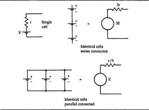
When the cells are connected in parallel, the voltage is as for one cell, but the internal resistance is much lower, because it is the resultant of several internal resistances in parallel. This allows much larger currents to be drawn, but unless the cells each produce exactly the same EMF value, there is a risk that current will flow between cells, causing local overheating. For this reason, primary cells are never used connected in parallel, and even secondary cells, which are more able to deliver and to take local charging current, are seldom connected in this way except for recharging.
Higher currents are obtained by making primary cells in a variety of sizes, with the larger cells being able to provide more current, and having a longer life because of the greater quantity of essential chemicals. The limit to size is portability, because if a primary cell is not portable it has a limited range of applications. Secondary cells have much lower internal resistance values, so that if high current capability is required along with small volume, a secondary cell is always used in preference to a primary cell. One disadvantage of the usual type of nickel–cadmium secondary cell in this respect, however, is a short ‘shelf life’, so that if equipment is likely to stand for a long time between periods of use, secondary cells may not be entirely suitable, because they will always need to be recharged just before use.
The important parameters for any type of cell are its open-circuit voltage (the EMF), its ‘typical’ internal resistance value, its shelf life, active life and energy content. The shelf life indicates how long a cell can be stored, usually at a temperature not exceeding 25°C, before the amount of internal chemical action seriously decreases the useful life. The active life is less easy to define, because it depends on the current drain, and it is usual to quote several figures of active life for various average current drain values. The energy content is defined as EMF × current × active life, and will usually be calculated from the most favourable product of current and time. The energy content is more affected by the type of chemical reaction and the weight of the active materials than by details of design.
Cell origins
All of the cells that are used today can trace their origins to the voltaic pile that was invented by Alessandro Volta around 1782. Each portion of this device was a sandwich of cloth soaked in brine, Figure 7.2(a) and laid between one plate of copper and one plate of zinc. When sufficient of the sandwich cells were assembled into a battery, the voltage was enough to cause effects such as the heating of a thin wire, or the twitching of the leg of a (dead) frog – the effect discovered by Luigi Galvani. The sort of electrical systems we get in Italian cars came much later!

Figure 7.2 (a) Volta’s original cell principle, and the battery (pile) derived from it. (b) The original form of wet simple cell.
The next step was the simple cell, as we now call it, which used the metal zinc (the cathode) and the liquid sulphuric acid to provide the chemical reaction, and the other contact, the anode, that was needed was provided by a copper plate which was also dipped into the acid, Figure 7.2(b). The action is that when the zinc dissolves in the acid, electrons are liberated. These electrons can flow along a wire connected to the zinc, and back into the chemical system through the copper plate, so meeting the requirement for a closed path for electrons.
In terms of conventional current flow, a decision made long before the existence of electrons was suspected, this is a current flowing from the positive copper plate, the anode, to the negative zinc plate, the cathode. All cells conform to this pattern of a metal dissolving in an acid or alkaline solution and releasing electrons that return to the cell by way of an inert conductor which is also immersed in the solution. The original zinc–sulphuric acid type of cell is known as the simple cell to distinguish it from the many types that have followed.
The simple cell has several drawbacks that make it unsuitable for use other than as a demonstration of principles. The use of sulphuric acid in liquid form makes the cell unsuitable for any kind of portable use, since acid can spill and even at the dilution used for the simple cell it can cause considerable damage. The cell cannot be sealed, because as the zinc dissolves it liberates hydrogen gas which must be vented.
There are more serious problems. The sulphuric acid will dissolve the zinc, although at a slower rate, even when no circuit exists, so that the cell has a very short shelf life and not much active life. In addition, the voltage of the cell, which starts at about 1.5 V, rapidly decreases to zero when even only a small current is taken because the internal resistance rises to a large value as the cell is used. This makes the cell unusable until the zinc is removed, washed, and then reinserted. No doubt if Alessandro Volta had been working with a government grant rather than on private funds, he would have been told that his experiments were leading nowhere and would no longer be funded (and what use, pray, could ever be found for such an invention?).
The efforts that were made to understand the faults of the simple cell have led to the development of considerably better cells, because by understanding principles we are better able to design new products. The problem of the zinc dissolving even with no circuit connected was solved by using very pure zinc or by coating the zinc with mercury. The problem is one of local action, meaning that the impurities in the zinc act like anodes, forming small cells that are already short circuited. By using very pure zinc, this local action is very greatly reduced, but in the eighteenth century purification of metals had not reached the state that we can expect nowadays. Mercury acts to block off the impurities without itself acting as an anode, and this was a much easier method to use at the time.
The rapid increase in internal resistance proved to be a more difficult problem, and one that could not be solved other than by redesigning the cell. Curiously enough, however, the problem of the increasing internal resistance was later used as a way of constructing electrolytic capacitors, see Chapter 1. The problem is that dissolving zinc in sulphuric acid releases hydrogen gas, and this gas coats the surface of the anode as it is formed, an action that was originally called polarization. The gas appears at the anode because of the action of the electrons entering the solution from the external circuit. Because hydrogen is an insulator, the area of the anode that can be in electrical contact with the sulphuric acid is greatly reduced by this action, so that the internal resistance increases. When local action is present, the internal resistance will increase from the moment that the cell is assembled, although for the pure-zinc cell or the type in which the zinc has been coated (amalgamated) with mercury, the internal resistance increases only while the cell is used.
The problem can be solved only by removing the hydrogen as it forms or by using a chemical reaction that does not generate any gas, and these are the solutions that have been adopted by every successful cell type developed since the days of Volta. The removal of hydrogen is achieved by using an oxidizing material, the depolarizer, which has to be packed around the anode. The depolarizer must be some material that will not have any chemical side-effects, and insoluble materials like manganese (II) oxide have been used very successfully in the past and are still widely used.
The Leclanché cell
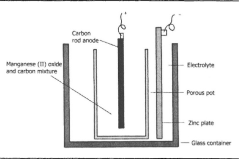
The cell that was developed by the French chemist Leclanché in the nineteenth century has had a remarkably long history, and in its ‘dry’ form is still in use, although now grandified by the title of carbon–zinc cell. In its original form, Figure 7.3, the electrolyte was a liquid, a solution of ammonium chloride. This is mildly acid, but not fiercely corrosive in the way that sulphuric acid is, and one consequence of using this less acidic electrolyte is that the zinc, even if not particularly pure, does not dissolve in the solution to the same extent when no current is passing in the external circuit. Local action is still present, but greatly reduced as compared to a zinc–acid type of cell. The anode for the cell is a rod of carbon, a material that is chemically inert and therefore unattacked by the electrolyte. The carbon rod is surrounded by a paste of manganese dioxide, all contained inside a porous pot so that the electrolyte keeps the whole lot wet and conducting. The action when current flows is that zinc dissolves in the mildly acid solution, releasing electrons which then travel through the circuit.
At the anode, the electrons would normally react with the water in the liquid to produce hydrogen, but the action of the manganese dioxide is to absorb electrons in preference to allowing the reaction with the water to proceed, producing a different oxide of manganese (a reduced state). As the cell operates, the zinc is consumed, as also is the manganese dioxide, and when either is exhausted the cell fails. The open-circuit voltage is about 1.5 V, and the internal resistance can be less than one ohm. The older form of the Leclanché cell was in service for operating doorbells and room indicators from mid-Victorian times, and some that had been installed in these days were still working in the late 1930s.
The reason is that the Leclanché cell was quite remarkably renewable. The users could buy spare zinc plates, spare ammonium chloride (which could also be used for smelling salts) and spare manganese dioxide, so that the cell could be given an almost indefinite life on the type of intermittent use that it had. Some worked for well over twenty years without any attention at all, tucked away in a cupboard on a high shelf.
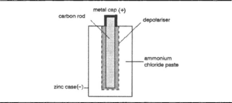
The ‘dry’ form of the Leclanché cell is the type that until quite recently was the only familiar form of primary cell. The construction, Figure 7.4, follows the principles of the older wet type of cell, but the ammonium chloride electrolyte is in jelly form rather than liquid, and the manganese oxide is mixed with graphite and with some of the jelly to keep it also moist and conducting. The action is the same, but because the dry cell is usually smaller than the wet variety and because its jelly electrolyte is less conductive, this form of the cell has generally a higher internal resistance than the old wet variety. The advantage of portability, however, totally overrules any disadvantages of higher internal resistance, making this the standard dry cell for most of the twentieth century.
The carbon–zinc dry cell, as it is more often called now, fails totally either when the zinc is perforated or when the manganese dioxide is exhausted. One of the weaknesses of the original design is that the zinc forms the casing for the cell, so that when the zinc becomes perforated, the electrolyte can leak out, and countless users of dry cells will have had the experience of opening a torch or a transistor radio battery compartment to find the usual sticky mess left by leaking cells. The term ‘dry’ cell never seems quite appropriate in these circumstances. The problem cannot simply be dealt with by using a thicker zinc casing and by restricting the amount of manganese dioxide so that the cell fails because of high internal resistance before the zinc is used up.
The carbon–zinc cell does not have a particularly long shelf life and once it has been used, the electrolyte starts to dissolve the zinc at a slow but inexorable rate. This corresponds to an internal current within the cell, called the self-discharge current. Perforation will therefore invariably occur when an exhausted cell is left inside equipment, and the higher the temperature at which the cell is kept, the faster is the rate of attack of the zinc.
This led to the development of leakproof cells with a steel liner surrounding the zinc. Leakproofing in this way allowed a much thinner zinc shell to be used, so cutting the cost of the cell (although it could be sold at a higher price because of the leakproofing) and allowing the cell to be used until a much greater amount of the zinc had been dissolved. Leakproofing is not foolproof, and even the steel shell can be perforated in the course of time, or the seals can fail and allow electrolyte to spill out. Nevertheless, the use of the steel liner has considerably improved the life of battery-operated equipment.
The alkaline primary cells
A different group of cell types makes use of alkaline rather than acid electrolytes, so that although the principle of a metal dissolving in a solution and releasing electrons still holds good, the detailed chemistry of the reaction is quite different. On the assumption that the reader of this book will be considerably more interested in the electrical characteristics of these cells rather than the chemistry, we will ignore the chemical reactions unless there is something about them that requires special notice. One point that does merit attention is that the alkaline reactions do not generate gas, and this allows the cells to be much more thoroughly sealed than the zinc–carbon type. It also eliminates the type of problems that require the need of a depolarizer, so that the structure of alkaline cells can, in theory at least, be simpler than that of the older type of cell. Any attempt to recharge these cells other than by well-designed (microprocessor-controlled) circuitry will generate gas and the pressure will build up until the container fractures explosively.
The best-known alkaline type of cell is the manganese—alkaline, whose construction is illustrated in Figure 7.5. This was invented by Sam Ruben in the USA in 1939 and was used experimentally in some wartime equipment, but the full-scale production of manganese-alkaline cells did not start until the 1960s. The cell uses zinc as the cathode, with an electrolyte of potassium hydroxide solution, either as liquid or as jelly, and the anode is a coating of manganese (II) oxide mixed with graphite and laid on steel. The cell is sealed because the reaction does not liberate gas, and the manganese (II) oxide is being used for its manganese content rather than for its oxygen content as a depolarizer.

The EMF of a fresh cell is 1.5 V, and the initial EMF is maintained almost unchanged for practically the whole of the life of the cell. The energy content, weight for weight, is higher than that of the carbon–zinc cell by a factor of 5–10, and the shelf life is very much better due to an almost complete lack of secondary action. All of this makes these cells very suitable for electronics use, particularly for equipment that has fairly long inactive periods followed by large current demand. Incidentally, although the cells use alkali rather than acid, potassium hydroxide is a caustic material which will dissolve the skin and is extremely dangerous to the eyes. An alkaline cell must never be opened, nor should any attempt ever be made to recharge it other than with specialized charging equipment.
Miniature (button) cells
The miniature cells are the types specified for deaf-aids, calculators, cameras and watches, but they are quite often found in other applications, such as for backup of memory in computing applications and for ‘smart-card’ units in which a credit card is equipped with a complete microprocessor and memory structure so that it keeps track of transactions. The main miniature cells are silver oxide and mercury, but the term mercury cell can be misleading, because metallic mercury is not involved.
The mercuric oxide button cell, to give it the correct title, uses an electrolyte of potassium hydroxide (Figure 7.6) which has had zinc oxide dissolved in it until saturated, so that the cell can be classed as an alkaline type. The cathode is the familiar zinc, using either a cylinder of perforated zinc foil or a sintered zinc-powder cylinder fastened to the button-top of the cell and insulated from the bottom casing. The anode is a coating of mercury (I) oxide mixed with graphite to improve conductivity and coated on nickel-plated steel or stainless steel which forms the casing of the cell. The EMF of such cells is low, 1.2–1.3 V, and the energy content is high, with long shelf life due to the absence of local action.

The silver oxide cell is constructed in very much the same way as the mercuric oxide cell, but using silver (I) oxide mixed with graphite as the anode. The cathode is zinc and the electrolyte is potassium hydroxide as for the mercuric oxide cell. The EMF is 1.5 V, a value that is maintained at a steady level for most of the long life of the cell. The energy content is high and the shelf life long.
All of these miniature cells are intended for very low current applications, so that great care should be taken to avoid accidental discharge paths. If the cells are touched by hand, this will leave a film of perspiration that is sufficiently conductive to shorten the life of the cell drastically. When these cells are fitted, they should be moved and fitted with tweezers, preferably plastic tweezers or with dry rubber gloves if you need to use your hands. These cells should not be recharged, nor disposed of in a fire. The mercury type is particularly hazardous if mercury compounds are released, and they should be returned to the manufacturer for correct disposal if this is possible, otherwise they should be disposed of by a firm that is competent to handle mercury compounds.
Lithium cells
Lithium is a metal akin to potassium and sodium which is highly reactive, so much so that it cannot be exposed to air and reacts with explosive violence with water. The reactive nature of lithium metal means that a water solution cannot be used as the electrolyte and much research has gone into finding liquids which ionize to some extent but which do not react excessively with lithium. A sulphur–chlorine compound, thionyl chloride, is used, with enough dissolved lithium salts to make the amount of ionization sufficient for the conductivity that is needed. The lithium cell is the most recently developed type of cell, remarkable for its unexpectedly high EMF.
The lithium, Figure 7.7, is coated on to a stainless-steel mesh which is separated from the rest of the cell by a porous polypropylene container. The anode is a mixture of manganese (II) oxide and graphite, also coated on to stainless-steel mesh. The whole cell is very carefully sealed. The reaction can be used to provide a cell with an exceptionally high EMF of 3.7 V, very long shelf life of ten years or more, and high energy content. The EMF is almost constant over the life of the cell, and the internal resistance can be low.

Lithium cells are expensive, but their unique characteristics have led to them being used in automatic cameras where focusing, film wind, shutter action, exposure and flash are all dependent on one battery, usually a two-cell lithium type. For electronics applications, lithium cells are used mainly for memory backup, and very often the life of the battery is as great as the expected lifetime of the memory itself. The cells are sealed, but since excessive current drain can cause a build-up of hydrogen gas, a ‘safety valve’ is incorporated in the form of a thin section of container wall which will blow out in the event of excess pressure. Since this will allow the atmosphere to reach the lithium, with risk of fire, the cells should be protected from accidental overcurrent, which would cause blowout. A recommended protection circuit is illustrated in Figure 7.8.

Figure 7.8 A recommended reverse-current protection circuit for a lithium cell in a simple backup application.
This is for use in applications where the lithium cell is used as a backup, so that D1 conducts during normal memory operation and D2 conducts during backup. Short-circuit failure of D2 would cause the lithium cell to be charged by the normal supply, and the resistor R will then limit the current to an amount which the cell manufacturer deems to be safe. If the use of a resistor would cause too great a voltage drop in normal backup use, it could be replaced by a quick-blowing fuse, but this has the disadvantage that it would cause loss of memory when the main supply was switched off.
Lithium cells must never be connected in parallel, and even series connection is discouraged and limited to a maximum of two cells. The cells are designed for low load currents, and Figure 7.9 shows a typical plot of battery voltage, current and life at 20°C. Some varieties of lithium cells exhibit voltage lag, so that the full output voltage is available only after the cell has been on load for a short time – the effect becomes more noticeable as the cell ages. Another oddity is that the capacity of a lithium cell is slightly lower if the cell is not mounted with the + ve terminal uppermost.

Secondary cells
A secondary cell makes use of a reversible chemical process, so that when the cell is discharged, reverse current into the cell will recharge it by restoring the original chemical constitution. Unlike primary cell reactions, reversible reactions of this type are unusual and only two basic types are known, the lead–acid type and the alkali–metal type, both of which have been used for a considerable time.
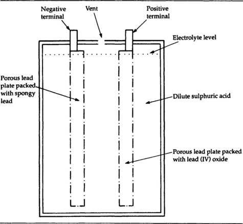
The lead–acid cell construction principle is illustrated in Figure 7.10. Both plates are made from lead and are perforated to allow them to be packed with the active materials. One, the positive plate (anode), is packed with lead (IV) oxide, and the negative plate (cathode) is packed with spongy or sintered lead which has a large surface area. Both plates are immersed in sulphuric acid solution. The acidity is much greater than that of the electrolytes of any of the acidic dry cells, and very great care must be taken when working with lead-acid cells to avoid any spillage of acid or any charging fault that could cause the acid to boil or to burst out of the casing. In addition, the recharging of a vented lead–acid cell releases hydrogen and oxygen as a highly explosive mixture which will detonate violently if there is any spark nearby.
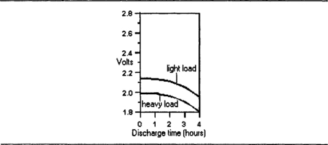
The EMF is 2.2 V (nominally 2.0 V), and the variation in voltage is quite large as the cell discharges. Figure 7.11 shows typical discharge graphs for light-load and heavy-load respectively.
The older vented type of lead–acid cell is now a rare sight, and modern lead–acid cells are sealed, relying on better control of charging equipment to avoid excessive gas pressure. The dry type of cell uses electrolyte in jelly form so that these cells can be used in any operating position. Cells that use a liquid electrolyte are constructed with porous separator material between the plates so that the electrolyte is absorbed in the separator material, and this allows these cells also to be placed in any operating position. Since gas pressure build-up is still possible if charging circuits fail, cells are equipped with a pressure-operated vent that will reseal when pressure drops again.
Lead–acid cells are used in electronics applications mainly as backup power supplies, as part of uninterruptible power systems, where their large capacities and low internal resistance can be utilized. Capacity is measured in ampere-hours, and sizes of 9 Ah to 110 Ah are commonly used. Care should be taken in selecting suitable types – some types of lead–acid cells will self-discharge considerably faster than others and are better suited to applications where there is a fairly regular charge/discharge cycle than for backup systems in which the battery may be used only on exceptional occasions and charging is also infrequent. Figure 7.12 shows the self-discharge rates of jelly-electrolyte cells at various temperatures, taking the arbitrary figure of 50% capacity as the discharge point.

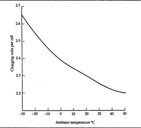
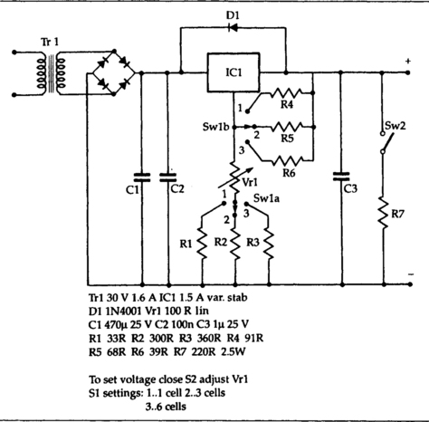
Lead–acid batteries need to be charged from a constant-voltage source of about 2.3 V per cell at 20°C – Figure 7.13 shows the variation of charging voltage per cell with ambient temperature of the cell. Cells can be connected in series for charging provided that all of the cells are of the same type and equally discharged. A suitable multi-cell charger circuit is illustrated in Figure 7.14, courtesy of RS Components.
For batteries of more than 24 V (12 cells) the charging should be in 24 V blocks, or a charging system used that will distribute charging so that no single cell is being overcharged. Parallel charging can be used if the charger can provide enough current. The operating life of a lead–acid cell is usually measured in terms of the number of charge/discharge cycles, and is greater when the cell is used with fairly high discharge currents – the worst operating conditions are of slow discharge and erratic recharge intervals – the conditions that usually prevail when these cells are used for backup purposes.
One condition to avoid is deep discharge, when the cell has been left either on load or discharged for a long period. In this state, the terminal voltage falls to 1.6 V or less and the cell is likely to be permanently damaged unless it is immediately recharged at a very low current over a long period. Typical life expectancy for a correctly operated cell is of the order of 750–6000 charge/discharge cycles.
NICKEL-CADMIUM CELLS
The original type of alkaline secondary cell, invented by Edison at the turn of the century, was the nickel-cathode iron-anode type, using sodium hydroxide as the electrolyte. The EMF is only 1.2 V, but the cell can be left discharged for long periods without harm, and will withstand much heavier charge and discharge cycles than the lead–acid type. Although the nickel–iron alkaline secondary cell still exists powering milk–floats and fork-lift trucks, it is not used in the smaller sizes because of the superior performance of the nickel–cadmium type of cell which is now the most common type of secondary cell used for cordless appliances and in electronics uses.
Nickel–cadmium cells can be obtained in two main forms, mass-plate and sintered plate. The mass-plate type used nickel and cadmium plates made from smooth sheet, the sintered type has plates formed by moulding powdered metal at high temperatures and pressures, making the plates very porous and of much greater surface area. This makes the internal resistance of sintered-plate cells much lower, so that larger discharge currents can be achieved. The mass-plate type, however, have much lower self-discharge rates and are more suitable for applications in which recharging is not frequent. Typical life expectancy is from 700 to 1000 charge/discharge cycles.
One very considerable advantage of the nickel–cadmium cell is that it can be stored for 5 years or more without deterioration. Although charge will be lost, there is nothing corresponding to the deep discharge state of lead–acid cells that would cause irreversible damage. The only problem that can lead to cell destruction is reverse polarity charging. The cells can be used and charged in any position, and are usually supplied virtually discharged so that they must be fully charged before use. Most nickel–cadmium cell types have a fairly high self-discharge rate, and a cell will on occasions refuse to accept charge until it has been ‘reformed’ with a brief pulse of high current. Cells are usually sealed but provided with a safety vent in case of incorrect charging.
In use, the nickel–cadmium cell has a maximum EMF of about 1.4 V, 1.2 V nominal, and this EMF of 1.2 V is sustained for most of the discharge time. The time for discharge is usually taken arbitrarily as the time to reach an EMF of 1 V per cell, and Figure 7.15 shows typical voltage–time plots for a variety of discharge rates. These rates are noted in terms of capacity, ranging from one-fifth of capacity to five times capacity, when capacity is in ampere-hours and discharge current in amps. For example, if the capacity is 10 Ah, then a C/5 discharge rate means that the discharge current is 2 A.

Charging of nickel–cadmium cells must be done from a constant-current source, in contrast to the constant-voltage charging of lead–acid types. The normal rate of charge is about one-tenth of the Ah rate, so that for a 20 Ah cell, the charge rate would be 2 A. Sintered types can be recharged at faster rates than the mass-plate type, but the mass-plate type can be kept on continuous trickle charge of about 0.01 of capacity (for example, 10 mA for a cell of 1 Ah capacity). At this rate, the cells can be maintained on charge for an extended period after they are fully charged, but this overcharge period is about three times the normal charging time. Equipment such as portable and cordless phones which would otherwise be left on charge over extended intervals such as bank holiday weekends and office holidays should be disconnected from the charger rather than left to trickle charge. This means that a full charge will usually be needed when work resumes, but the life of the cells can be considerably extended if the very long idle periods of charging can be avoided. Another option is to leave the equipment switched on so as to discharge the cells, and fit the mains supply with a timer so that there will periodic recharging.
Figure 7.16 shows a recommended circuit for recharging, courtesy of RS Components. This uses a 7805 regulator to provide a fixed voltage of 5 V across a resistor, so that the value of the current depends on the choice of resistor and not on the voltage of the cell. The value of the resistor has to be chosen to suit the type of cell being recharged; values from 10 Ω to 470 Ω are used depending on the capacity of the cell. Because the regulator system is floating with respect to ground, this can be used for charging single cells or series sets of a few cells. Ready-made chargers are also available which will take various cells singly or in combination, with the correct current regulation for each type of cell.

• A form of silver cell has also been used in rechargeable form. This uses an anode of porous zinc, usually a sintered component, with a silver (I) oxide and graphite cathode. The electrolyte is potassium hydroxide solution that has been saturated with zinc hydroxide. The cell can take a limited number of recharging cycles, but is now uncommon.