
Hardware
The hardware of electronics, meaning the chassis, covers, cabinets, switches and other ‘external’ features, is almost as important as the circuitry within, because the hardware is all that the casual user can use to judge the system. British manufacturers of hi-fi systems (about all that survives of the UK consumer electronics industry) are by now well aware of this, although it seems that we have the strange distinction of making as much valve-equipped hi-fi as transistorized versions. For consumer applications, the look of hardware is important, but for military contracts, adhering to specifications is what counts. On all scores hardware cannot be neglected, although it very often is. The task is made much easier when there is a company policy of using some particular form of hardware such as standardized board and cabinet sizes. The most difficult decision is on how to package some piece of equipment that is for the moment a one-off product, particularly if there is any chance that other items will follow.
Terminals and connectors
The prospective user of a piece of electronics equipment first makes contact with the design when he/she tries to connect it to other equipment and to whatever power supply is used. Mains-operated equipment for domestic or office use will have a connected and well-tethered mains cable of the correct rating, preferably with a correctly fused 3-pin plug if it is intended for the UK market. The option is to use a BS/IEC approved 3-pin plug on the chassis, with a lead that has a matching socket at one end and a suitable mains plug at the other. Mains cables can be obtained as a standard item with the BS/IEC fitting at one end and various UK or other plugs at the other. If additional equipment has to be driven, BS/IEC sockets can be used to allow power to be taken from the main unit rather than from a set of additional mains cables. Only low-power and double-insulated equipment should use the 2-pin form of cassette recorder leads because these provide small contact area and are not mechanically well secured.
Industrial equipment for UK use will use one of the approved industrial connectors, almost certainly to the BS 4343 specification for equipment to be used in the UK. The BS scheme specifies two digits, but the third which is illustrated can be added to show protection against mechanical impact.
Mains connections are about as standardized as anything in the use of terminals ever attains. When we look at what is available for low-voltage connectors and for signal connectors, there is a bewildering variety of styles available. The primary aim in choosing connections should be to achieve some co-ordination with the equipment that will be used along with yours, and this means that you need to have, from the start of the design stage, a good idea of what amounts to de facto standards. If no such standards exist, try to resist making new ones because there are far too many already.
One example is the low-voltage supply connector which is used for cassette recorders, portable stereo players and for some calculators. Even in this very restricted range of applications there are two sizes of plug/socket, the 2.1 mm and the 2.5 mm, with some manufacturers using the centre pin as ground and others using the centre pin as the supply voltage pin (usually 6 V), so that there can be four variations on this design alone. Power supplies for such equipment usually cope by using a lead that is terminated in a 4-way jack plug and which at the supply end is fitted with a reversible plug, often with no polarity markings.
Getting the correct polarity is very often more a matter of luck than good instructions, so that if this type of connector is used there should be a clear indication of polarity and also some protection against use of the wrong polarity (a diode in series) if this can be tolerated. In some cases the use of a diode imposes an excessive voltage drop and protection is very difficult to achieve at reasonable cost. A more elaborate method, with a much lower voltage drop, is illustrated in Figure 9.1 (due to Bob Pease). The voltage drop across the FET is much less than the 0.5 V (minimum) across a diode.

Figure 9.1 A circuit due to Bob Pease which will protect a load against accidental voltage reversal.
The main confusion, however, exists among signal connectors, and the only possible advice here is to try to stay with industry standards for comparable equipment. For educational equipment, for example, the 4 mm plug and socket is almost universal, and for connecting UHP signals to a domestic TV receiver the standard coaxial plug and socket type should be used. Connections to TV receivers that are being used as monitors often use the SCART form of Euroconnector, see later, but for other connections, particularly for computer monitors, standards can vary widely. Fortunately, the almost universal adoption of the IBM PC standards everywhere except in education (where they are most needed) ensures reasonable uniformity.
The largest range of connectors is found in the TV and video ranges, with audio coming a close second. RF connectors are used for radio transmitters, including CB and car telephone uses, and for a variety of VHF and UHF work, and although virtually all coaxial in design, offer a wide range of fittings, whether bayonet or screw retained. The wide range of connectors reflects the wide range of VHF and UHF cables, so that you cannot necessarily use any type of connector with any type of cable. Generally, connectors are made to work with a limited range of cables, although in some cases the range can be extended by using adapters.
The range of RF connectors is intended to match the range of RF cables, of which Table 9.1 shows a summary only, in which some of the better-known cable types are arranged into groups. RF cables are identified by Uniradio numbers or by RG numbers. Both systems of classification are in widespread use in the UK, but the RG set, of US origin, is better known worldwide. The main measurable features of an RF cable are the characteristic impedance to which the cable must be matched in order to avoid reflections, the capacitance per metre, and the attenuation in dB per 10 m at various RF frequencies. All of the cable groups illustrated are coaxial and the characteristic impedance is virtually always either 50 Ω or 75 Ω, but the attenuation characteristics differ considerably from one cable type to another. Most of the RF cables are rated to withstand high voltages between inner and outer conductors, often exceeding 20 kV.
Table 9.1
A selection of the RG standards for RF cables
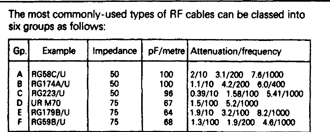
The UR series of cables are to UK Uniradio standards, the RG set are to US standards. Capacitance is quoted in picofarads per metre length, and the attenuation is shown in db per 10m length of cable in MHz. at selected frequencies.
For example. 5.2/1000 means 5.2 db attenuation at 1000 mHz for a 10m length of cable.
• Characteristic impedance values of 53 Ω and 93 Ω are used in the USA, and another standardized impedance, used for microstrip, is 100 Ω.
The various connectors are likely to be used for other than RF cable connectors, of course, and there is a wide range of other coaxial cables which will fit one connector type or another and to which the connectors will match well. These applications include audio, video and digital network signal applications.
The BNC range of connectors covers both 50 Ω and 75 Ω types which are manufactured for an assortment of cable sizes. All feature a bayonet locking system, and a maximum diameter of about 15 mm, and both solder and crimp fittings are available. The standard range of BNC connectors can be used in the frequency range up to 4 GHz (absolute maximum 10 GHz) and with signal voltage levels up to 500 V peak. Terminations and attenuators in the same series are also obtainable, and there is also a miniature BNC type, 10 mm diameter, with the same RF ratings, and a screw-retained version, the TNC couplers. The connectors of this family offer a substantially constant impedance when used with the recommended cables.
The SMA series of connectors are to BS 9210 N0006 and MIL-C-39012, and are screw retained. This provides more rigidity and improves performance under conditions such as vibration or impact. The voltage rating is up to 450 V peak, and frequencies up to 12.4 GHz on flexible cable, and up to 18 GHz on semi-rigid cable, are usable. The VSWR (voltage standing wave ratio, ideally equal to 1) which measures reflection in the coupling is low at the lower frequencies but changes with frequency, usually showing a peak at some frequency. A typical quoted formula for semi-rigid cable coupling is 1.07 + 0.008/f with f in GHz, so that for a 10 GHz signal the VSWR would be 1.07 + 0.008 × 10 = 1.15. The body material is stainless steel, gold plated, with brass or beryllium–copper contacts and a PTFE insulator. The typical operating temperature range is –55°C to +155°C.
The SMB (sub-miniature bayonet) range is to BS 9210 and MIL-C-93012B specifications and has a 6 mm typical diameter, rated for 500 V signal peak in the frequency range up to 4 GHz. The VSWR is typically around 1.4 for a straight connector and 1.7 for an elbowed type, and both solder and crimp fittings are available. SMC (subminiature screw) connectors are also available to the same BS and MIL specifications.
The older UHF plug series are also to MIL specifications, but with the limited frequency range up to about 500 MHz. These are larger connectors, typically 19 mm diameter for a plug, with screw clamping, and they are particularly well suited to the larger cable sizes. They are often used for video signal coupling.
There are adapters available for every possible combination of RF connector, so that total incompatibility of leads should never arise. This is not a perfect solution, however, because the use of an adapter invariably increases the VSWR figure, and it is always better to try to ensure that the correct matching plug/socket is used in the first place.
Video connectors
Video connections can make use of the VHF type of RF connectors, or more specialized types. These fall into two classes, the professional video connectors intended for use with TV studio equipment, and the domestic type of connector as used on video recorders to enable dubbing from one recorder to another or from a recorder to a monitor so that the replayed picture can be of better quality than is obtainable using the usual RF modulator connection to the aerial socket of TV receivers. Many video recorders nowadays use nothing more elaborate than an audio style (RCA) phono connector for their video as well as their audio output, and a SCART socket for connection to the TV receiver, with possibly another SCART for connection to satellite or other digital decoder.
For studio use, video connectors for a camera may have to carry a complete set of signals, including separate synchronizing signals, audio telephone signals for a camera operator, and power cables as well as the usual video-out and audio-out signals. Multiway rectangular connectors can be used for such purposes, with 8-way for small installations and 20-way connections for connections to editing consoles and similar equipment. These connectors feature very low contact resistance, typically 5 mΩ. For smaller equipment, circular cross-section connectors of about 17 mm overall diameter are used, carrying ten connectors with a typical contact resistance of 14 mΩ and rated at 350 V AC.
Audio connectors start with the remarkably long-lived jacks which were originally inherited (in the old ![]() in size) from telephone equipment. Jacks of this size are still manufactured, both in mono (2-pole) and stereo (3-pole) forms, and with either chassis mounted or line sockets. Their use is now confined to professional audio equipment, mainly in the older range, because there are more modern forms of connectors available which have a large contact area in comparison to their overall size. Smaller versions of the jack connector are still used to a considerable extent, however, particularly in the stereo form. The 3.5 mm size was the original miniature jack, and is still used on some domestic equipment, but the 2.5 mm size has become more common for mono use in particular.
in size) from telephone equipment. Jacks of this size are still manufactured, both in mono (2-pole) and stereo (3-pole) forms, and with either chassis mounted or line sockets. Their use is now confined to professional audio equipment, mainly in the older range, because there are more modern forms of connectors available which have a large contact area in comparison to their overall size. Smaller versions of the jack connector are still used to a considerable extent, however, particularly in the stereo form. The 3.5 mm size was the original miniature jack, and is still used on some domestic equipment, but the 2.5 mm size has become more common for mono use in particular.
One of the most common forms of connector for domestic audio is still the phono connector, devised by RCA, whose name indicates its US origins. Phono connectors are single channel only, but are well screened and offer low-resistance connections along with sturdy construction. The drawback is the number of fittings needed for a 2-way stereo connection such as would be used on a stereo recorder, and for such purposes DIN plugs are more often used, particularly in European equipment. Many users prefer the phono type of plug on the grounds of lower contact resistance and more secure connections. At one time, DIN connectors were almost unknown in the USA, but they have been introduced in computing applications, notably as the keyboard connector for the older IBM PC machines. The later PS/2 type of connector is similar in size and style, but with a quite different pin arrangement and a different locating system.
The European DIN (Deutsches Industrie Normallschaft, the German standardizing body) connectors use a common shell size of 15 mm diameter for a large range of connections from the loudspeaker 2-pole type to the 8-way variety. Although the shell is common to all, the layouts (Figure 9.2) are not. The original types are the 3-way and the 180° 5-way connectors, which had the merit of allowing a 3-way plug to be inserted into a 5-way socket. Later types, however, have used 240° pin configurations with 5, 6 and 7 contacts; 4-way and ground types with the pins in square format; and a 5-way ‘domino’ type with a central pin, along with the 8-way type which is configured like the 7-way 240° type with a central pin added. This has detracted from the original simplicity of the scheme, which was intended to make the connections to and from stereo domestic audio equipment easier.

Figure 9.2 The various 15 mm diameter DIN connector pin layouts for audio uses. There is also a 2-pin type (one round pin, one flat pin) for loudspeaker connections.
The more crowded layouts of DIN plugs and sockets are notoriously difficult to solder unless they have been mechanically well designed, using splayed connectors on the chassis mounted sockets and to some extent also on the line mounted plugs. Use of the 5-way 240° type is recommended for audio equipment other than professional grade equipment, but only where signal strengths are adequate and risk of hum pickup is minimal. The standard system of pin assignment should be adhered to if the connector is being used in its typical application, as input/output for a tape/cassette recorder. Latched connectors can be obtained to avoid the possibility of pulling the connectors apart accidentally. For low-level use, phono plugs are preferable.
For professional audio (or high-quality domestic audio) equipment, the XLR series of connectors provides multiple connections with much superior mechanical quality. These are available as 3-, 4-, or 5-pole types with anchored pins to which the cables are soldered, with set-screws used to retain the shells. The contacts are rated to 15 A for the 3-pole design (lower for the others) and they can be used for a maximum working voltage of 120 V. Contact resistance is low, and the connectors are latched to avoid accidental disconnection. There is a corresponding range of loudspeaker connectors to the same high specifications.
• You may need to specify a grounded shell design if the connectors are to be used with shielded cables.
A variety of other connectors also exists, such as the EPX series of heavy-duty connectors and the MUSA coaxial connectors. These are more specialized and would be used only in their specialized applications, they are not found used as general-purpose connectors.
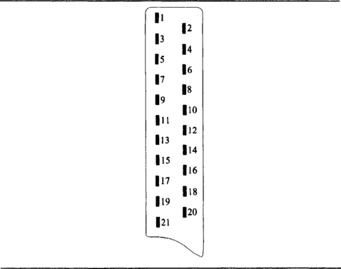
THE SCART CONNECTOR
This device, Figure 9.3 and Table 9.2, is known variously as the SCART, Peritelevision or Euroconnector. It provides a standard 21-pin interface designed to allow various peripheral devices to be connected to a TV receiver. Whilst the physical arrangement of the connector and its pins and some of the connections have been standardized, there are a number of variants found in practice and these are shown in the table below. The device allows for connections to be made at standard RGB or baseband levels so that no remodulation is needed to provide input to the UHF aerial socket. The use of remodulation tends to degrade the picture quality due to mixer noise and tuner drift.
Table 9.2
| Pin | Connection |
| 1 | Right audio channel output |
| 2 | Right audio channel input |
| 3 | Left audio channel output |
| 4 | Audio screen/ground |
| 5 | Blue video screen/ground |
| 6 | Left channel audio input |
| 7 | Blue video Input |
| 8 | Source switching, 0 – off air, 1 – PeriTV |
| 9 | Green video screen/ground |
| 10 | Data bus |
| 11 | Green video input |
| 12 | Data bus |
| 13 | Red video screen/ground |
| 14 | Data bus ground |
| 15 | Red video input |
| 16 | Mode switch, 0 – composite video, 1 – fast video blanking |
| 17 | Composite video screen/ground |
| 18 | Common earth for pins 8 & 16 |
| 19 | Composite video output/computer sync input |
| 20 | Composite video input |
| 21 | Cable/connector shell ground |
COMPUTER CONNECTORS
Computer and other digital signal connections have, at least, reached some measure of standardization after a period of chaos. At one time, it was quite common to see edge connectors used for external connections, but this way of breaking circuit boards has now been abandoned, and edge connectors should be confined now to internal connections. Since the advent of the IBM PC style of computer, there are four main types of connector that are peculiar to computing and digital circuits.
The Centronics connector is used mainly for connecting a computer to a printer, and it consists of a 36-contact connector which uses flat contact faces. At one time, both computer and printer would have used identical fittings, but it is now more common for the 36-pin Centronics socket to be used only on the printer. At the computer a 25-pin subminiature D-connection is used, usually with the socket chassis mounted. In a normal connection from computer to printer, only eighteen of the pins are used for signals (including ground). The shape of the body shell makes the connector nonreversible.
The original form of Centronics parallel port was intended for passing signals in one direction only, from a computer to a printer. Several designers made use of the unmodified system for bi-directional signals by using the four signal lines that communicated in the reverse direction along with four data lines so as to get 4-bit bi-directional signalling. This in turn gave rise to a standardized system for allowing the use of the parallel port for 8-bit bi-directional signalling.
This is the standard IEEE Std. 1284–1994 system, and is otherwise known as the EPP (extended parallel port) system. The EPP system is used for modern printers to allow better software control so that, for example, an inkjet printer can signal that it is running low on ink, or a laser printer can signal that it is running low on toner. More significantly, the EPP has been used for industrial applications as an interface between the computer and machines connected to the computer and controlled by it. Printers of recent manufacture also feature a USB connection as an alternative.
The IEEE 1284 standard provides for high-speed signal transfer in both directions between the PC and an external peripheral. The speed of data can be 50 to 100 times faster than was possible using the older Centronics port, but the EPP connection on the PC is still fully compatible with older printers and other peripherals that use the parallel port. You can also use an EPP port along with an older Centronics port on the same PC.
The EPP type of port is standard on modern computers, and should normally be set up by using a (default) option in the CMOS ROM. The system offers five modes of operation, four of which maintain compatibility with older methods:
1. Data in forward direction only (out from computer), used for a normal Centronics printer connection.
2. Bi-directional action using four status lines for data in reverse direction along with four data lines in forward direction. This is also known as Nibble mode, and has also been used in cables for connecting two or three computers together in a simple network.
3. Hewlett-Packard Bitronics bi-directional mode, using data lines.
4. ECP (extended capability port) mode for printer and scanner use.
5. Fully bi-directional EPP mode used by some printers and also for computer peripherals such as external CD-ROM, hard drive, etc.
The older bi-directional systems require software to implement each transfer, and this limits the transfer rate to, typically, 50–100 Kbytes per second. Modern PC machines have a port that can be used for ECP and EPP modes, and the I/O controller chip firmware allows for direct control of the port action with a greatly reduced external software overhead. A good comparison is the difference between a DMA (Direct Memory Access) transfer and one made by using the processor to read data and write to memory.
• The IEEE-1284 standard also provides supporting protocols that allow the PC and its peripheral to agree on which mode to use. The standard also defines the cable and connector formats, with electrical signal specifications.
Having EPP/ECP capability on a computer does not guarantee that it will be used when you connect a printer to the port. The printer itself must be capable of operating (usually) in ECP mode, and the operating system must also be capable of using the ECP mode. Although an ECP port can operate in Centronics mode faster than the older type of parallel port, full ECP speed with a printer that can work in this mode requires the ECP port to be set up in the CMOS RAM, and the operating system to use it.
Three types of connectors can be used. One, Type A, is the existing DB25 type, updated to 1284 electrical standards. Type B and C are 36-pin connectors, of which the Type C is the standard that is recommended for new designs. Type C is smaller than older 36-pin types, uses a simple clip as anchor, and permits the use of additional signals, peripheral logic high and host logic high. These additional signals are used to find if the devices at each end of the cable are switched on.
Figure 9.4 shows these connectors; Types A and B are the familiar DB25 and Centronics types that are currently used.

The same 25-pin D-connector can be used for serial connections, but more modern machines use 9-pin sub-miniature D-sockets for this purpose, since no more than 9-pin connections are ever needed. For other connections, such as to keyboards, mice and monitors, DIN style connectors are often used, although the sub-miniature D-type connectors are also common. The D-type connectors are widely available in a range of sizes and with a large range of accessories in the form of casings, adapters and tools, so that their use of all forms of digital signals is strongly recommended.
There are now standard DIN fittings for edge connectors, including the more satisfactory indirect edge connectors that have now superseded the older direct style. The indirect connectors are mounted on the board and soldered to the PCB leads, avoiding making rubbing contacts with the board itself.
THE UNIVERSAL SERIAL BUS (USB)
The essential simplicity of serial connections for linking a computer to a peripheral has spurred designers into looking for something better than the old telecommunications serial ports that belong to the pre-computer age. The requirement was for a type of serial port that could be used for all the normal computer connections, and which could be connected in a ‘daisy-chain’ type of network with each device connected to another with only one of them needing to be connected directly to the computer.
The answer to this is called the universal serial bus (USB). It has been designed to be hot-plugged, meaning that devices can be connected and disconnected with the computer switched on and working. This is possible only if the system is supported by the computer, the peripheral device and the operating system.
USB permits communications between devices that are equipped with suitable interfaces at serial data rates ranging from 1.5 Mbits/s to 1.5 Mbytes/s. This is very much faster than the old-style serial port system. The interconnecting cable has a maximum length of 5 metres and consists of two twisted pair cables, one pair for power and the other for signalling. The distance can be extended to about 30 metres by using a hub terminal device as a line repeater.
Terminal devices, such as keyboard, mouse and printer, are added to the basic PC in a daisy-chain fashion and each is identified by using a 7-bit address code. This allows up to 127 devices, in theory at least, to be connected. In practice, not all devices allow daisy-chain connection (picture a mouse with two tails!), and so the computer needs more than one USB connector. Figure 9.5 shows the two main types of USB sockets in current use.

FIREWIRE (IEEE 1394–1995)
FireWire is a trademark of Apple Computers Inc. who, during 1988, originally designed and established this type of serial signalling system as the basis for a very fast, low cost and easy to use network for digital audio signals. The system has been developed and standardized by the Institution of Electrical and Electronics Engineers (IEEE) in the USA and is now well suited to be used as an interface for fast computer systems. Since 1995 the network has become an established IEEE standard which is supported by a worldwide trade organization of more than 90 manufacturers and constructors.
FireWire allows any device equipped with a suitable interface to be simply coupled to the computer to form a communication system. This flexibility now allows, for example, the home PC, the television receiver and telephone systems to be connected. Because FireWire allows hot-plugging (you can add or remove connections with the computer switched on) it makes interconnections very quick and simple for the non-technical user.
Any devices that are fitted with the appropriate interface can be coupled together through any one of a number of ports using a simple cable without any consideration for the order in which the devices appear on the network. The services currently available to this network include home video editing, security monitoring, photo-CD handling, image enhancement, video and teleconferencing, plus professional broadcast and industrial applications. Note that these are the applications that need faster transfer of bytes than can be achieved using USB.
FireWire terminal devices may be fitted with single input and multiple output port interfaces which can be coupled together through a special cable unit. Any new device can be added to the network by simply plugging into a spare port anywhere on the network. The devices may be coupled in a mix of clusters or stars or the daisy-chain format, the only restrictions being that there should be no more than sixteen hops between any two nodes and without any loops being formed. The maximum length with no repeaters is about 10 metres, but 4.5 metre lengths are more common.
The most important feature of FireWire is its simplicity, at least as far as the domestic user is concerned. Any new device may be plugged into a spare port without switching the power off and the system then dynamically reconfigures itself to suit the new situation without the need to reset any switches or jumpers.
Control knobs and switches
There is as great a variety in control knobs and switches as in terminals and connectors. Control knobs for rotary potentiometers are available in a bewildering range of sizes and styles, mostly using grub-screw (set-screw) fastening, although a few feature push-on fitting. For all but the least costly equipment, a secure fastening is desirable, but the traditional grub-screw is not entirely satisfactory because it can work loose and cause considerable delay when knobs have to be removed for servicing work. A more modern development is collet-fitting, using a split collet over the potentiometer shaft which is tightened down by a nut. The recess for the collet nut is then covered by a cap which can be colour coded or moulded with an arrow pointer. This is a much more satisfactory form of fitting.
A more specialized form of knob allows multi-turn use, so that ten to fifteen turns of the dial will be needed to rotate the potentiometer shaft from one end stop to the other. These multi-turn dials can use digital or analogue readouts and are normally located by a grub-screw with an Allen (hexagon) head.
Switches
Switches are required to make a low-resistance connection in the ON setting, and a very high-resistance insulation in the OFF setting. The resistance of the switch circuit when the switch is on (made) is determined by the switch contacts, the moving metal parts in each part of the circuit which will touch when the switch is on. The amount of the contact resistance depends on the area of contact, the contact material, the amount of force that presses the contacts together, and also in the way that this force has been applied.
If the contacts are scraped against each other in a wiping action as they are forced together, then the contact resistance can often be much lower than can be achieved when the same force is used simply to push the contacts straight together. In general, large contact areas are used only for high-current operation and the contact areas for low-current switches as used for electronics circuits will be small. The actual area of electrical connection will not be the same as the physical area of the contacts, because it is generally not possible to construct contacts that are precisely flat or with surfaces that are perfectly parallel when the contacts come together. The usual solution to this problem is to use a multiple-contact structure.
A switch contact can be made entirely from one material, or it can use electroplating to deposit a more suitable contact material. By using electroplating, the bulk of the contact can be made from any material that is mechanically suitable, and the plated coating will provide the material whose resistivity and chemical action is more suitable. In addition, plating makes it possible to use materials such as gold and platinum which would make the switch impossibly expensive if used as the bulk material for the contacts. It is normal, then, to find that contacts for switches are constructed from steel or from nickel alloys, with a coating of material that will supply the necessary electrical and chemical properties for the contact area. The usual choice of materials is the same as is used for relays (see Chapter 7), with the addition of copper and beryllium-copper.
Switch ratings are always quoted separately for AC and for DC, with the AC rating often allowing higher current and voltage limits, particularly for inductive circuits. When DC through an inductor is decreased, a reverse voltage is induced across the inductor, and the size of this voltage is equal to inductance multiplied by rate of change of current. The effect of breaking the inductive circuit is a pulse of voltage, and the peak of the pulse can be very large, so that arcing is almost certain when an inductive circuit is broken unless some form of suppression is used.
Arcing is one of the most serious of the effects that reduce the life of a switch. During the time of an arc very high temperatures can be reached both in the air and on the metal of the contacts, causing the metal of the contacts to vaporize, and be carried from one contact to the other. This effect is very much more serious when the contacts carry DC, because the metal vapour will also be ionized, and the charged particles will always be carried in one direction. Arcing is almost imperceptible if the circuits that are being switched run at low voltage and contain no inductors, because a comparatively high voltage is needed to start an arc. For this reason, then, arcing is not a significant problem for switches that control low voltage, such as the 5 V or 9 V DC that is used as a supply for solid-state circuitry, with no appreciable inductance in the circuit. Even low-voltage circuits, however, will present arcing problems if they contain inductive components, and these include relays and electric motors as well as chokes. Circuits in which voltages above about 50 V are switched, and particularly if inductive components are present, are the most susceptible to arcing problems, and some consideration should be given to selecting suitably rated switches, and to arc suppression, if appropriate.
The normal temperature range for switches is typically –20°C to +80°C, with some rated at –50°C to +100°C. This range is greater than is allowed for most other electronic components, and reflects the fact that switches usually have to withstand considerably harsher environmental conditions than other components. The effect of very low temperatures is due to the effect on the materials of the switch. If the mechanical action of a switch requires any form of lubricant, then that lubricant is likely to freeze at very low temperatures. Since lubrication is not usually an essential part of switch maintenance, the effect of low temperature is more likely to be to alter the physical form of materials such as low-friction plastics and even contact metals.
Flameproof switches must be specified wherever flammable gas can exist in the environment, such as in mines, in chemical stores, and in processing plants that make use of flammable solvents. Such switches are sealed in such a way that sparking at the contacts can have no effect on the atmosphere outside the switch. This makes the preferred type of mechanism the push-on, push-off type, since the pushbutton can have a small movement and can be completely encased along with the rest of the switch.
Switch connections can be made by soldering, welding, crimping or by various connectors or other screw-in or plug-in fittings. The use of soldering is now comparatively rare, because unless the switch is mounted on a PCB which can be dip-soldered, this will require manual assembly at this point. Welded connections are used where robot welders are employed for other connection work, or where military assembly standards insist on the greater reliability of welding. By far the most common connection method for panel switches, as distinct from PCB mounted switches, is crimping, because this is very much better adapted for production use. Where printed circuit boards are prepared with leads for fitting into various housings, the leads will often be fitted with bullet or blade crimped-on connectors so that switch connections can be made.
Fuses and circuit-breakers
All electronic circuits, unless of the microwatt variety powered by a high-impedance battery, must be fused so as to prevent damage that would be caused by excess current. The choice of fuses from the usual bewildering variety is much more strictly governed than the choice of other hardware items, however, because there are often national regulations which must be obeyed if fuses are being replaced or if electronic equipment is being exported. European standards specify fuses of 20 mm length and 5 mm diameter (20 × 5 fuses), whose specification is outlined by IEC 127. For the USA and Canada, however, the fuse standards are UL198G and CSA22–2 No. 59 respectively, using 1 ![]() in ×
in × ![]() in fuses whose characteristics in terms of blowing time and current are quite different from the European standards. These fuses are not of interchangeable dimensions but nevertheless great care should be taken not to mix the types. This is particularly important in the UK where 1
in fuses whose characteristics in terms of blowing time and current are quite different from the European standards. These fuses are not of interchangeable dimensions but nevertheless great care should be taken not to mix the types. This is particularly important in the UK where 1 ![]() in fuses which are to the IEC 127 standards on current and time characteristics are in use along with the 20 mm type.
in fuses which are to the IEC 127 standards on current and time characteristics are in use along with the 20 mm type.
The aim of a fuse is to interrupt current in the event of a fault that causes excessive current to flow. The subject is not nearly as simple as this would suggest, however. If a fuse is used in a circuit in which a high voltage would exist after the fuse blows, then that voltage placed across the fuse might be enough to cause an arc-over, so that current was not interrupted when the fuse blew. Fuses carry a voltage rating, and should not be used beyond that rating, so that a fuse rated at 125 V should not be used in a circuit in which 240 V could exist across a blown fuse. A fuse can be safely used at voltages lower than the rated maximum, but not at any voltage higher than the stated maximum.
The interrupt test rating of a fuse is another value which is not well known. A fuse rated at 1 A might never have to bear a current of 1000 A or more, but its behaviour at such high currents is important. If the fuse continued to pass current, for example, because of conduction by the metal vapour from the wire, it would once again be unsatisfactory. Approval testing for fuses is therefore carried out at very high currents as well as with high voltages across the fuse, and this figure is often quoted.
The quantity that is always quoted for a fuse is the nominal current rating, but precisely what that means depends on the standard to which the fuse has been constructed. A fuse which is rated at 1 A, for example, will not necessarily blow at a current of 1 A, because the blowing of a fuse is a complicated process that involves current and time, and the various standards exist to provide guidelines on the current–time limits. The three main fuse standards that you are likely to come across are the UL198G (USA), CSA22.2 (Canada) and the IEC 127 (Europe, including the UK). These standards are substantially different; a European 1 A fuse would be rated in the USA as 1.35 A, and this is typical over the range of ratings. European fuse ratings are aimed at protection against large overloads caused by short circuits; fuse ratings in the USA aim to provide overload protection from currents that are rather less than short-circuit levels.
Very great care must therefore be taken with equipment of overseas origin, or with equipment intended for export, that the fuse types are correct as well as the ratings. Figure 9.6 shows the corresponding ratings of three types of fuses with values on the IEC ratings and on the UL/CSA ratings. Probably the easiest way to remember the conversion is that the fast fuses are rated in the ratio 10/9 (10 A US fuse = 9 A Euro-fuse) and for the others the ratio is 8/6 (8 A US fuse = 6 A Euro-fuse).

Fuses are grouped in five major categories according to their current–time characteristics. At one end of the scale, semiconductor circuits need fuses that will act very quickly on short-circuit conditions. These are now described as super quick-acting fuses, coded FF. These, at ten times rated current, will blow in a millisecond or less, and for twice the rated current the blowing time will be 50 ms or less. The next group comprises the quick-acting class F fuses (classed as normal blo in the US), used for general-purpose protection where current surges are unlikely to be encountered. These have a slower blowing characteristic, some 10 ms for ten times rated current and just over 100 ms for twice rated current.
• No fuse, no matter how fast it blows, can adequately protect semiconductors. The use of fuses in semiconductor circuits is aimed as a last resort to avoid damage to other components.
The medium time-lag fuses (type M) will withstand small current overloads that might be caused by charging capacitors. These fuses will blow after about 30 ms on a ten times current overload, and after about 20 seconds on a two times overload. The long time for the smaller overload allows for current surges that are not particularly large but of quite long duration. The time-lag type T fuses (classed as slo-blo in the US) will blow in 100 ms for a ten times overload and in about 20 seconds for a twofold overload. Super time-lag class TT fuses allow for 150 ms at a tenfold overload and 100 seconds at a twofold overload.
All fuse ratings are measured at 20°C–25°C ambient temperature, and because the blowing of a fuse is a thermal process, the ratings of a fuse are affected by changes in the ambient temperature. The slower-blowing fuses in particular, which depend on the use of some heat-sinking to delay blowing, need to be derated if they are to be used at high ambient temperatures, and for these types, derating to 60% of nominal value is recommended if the fuse is to be used at 100°C. The derating for the faster-blowing types is considerably less, but in general fuses should not be located at a point in a circuit where high temperatures exist (such as next to a set of power transistors) unless this is done deliberately as a safety measure. Quite irrespective of any derating due to ambient temperature, the normal current through a fuse can be the fuse rated current for a European type of fuse, but not more than 75% of rated current for a US/Canada type of fuse.
Fuses are resistors, and although the larger capacity of fuses have a negligible resistance, this is not true of the smaller types. Fuse resistance is not usually quoted by suppliers, but it can add to the resistance of a power supply and upset stabilization to some extent, although for the larger rated fuses the contact between fuse and fuse-holder contributes more resistance in some cases.
Fuse specifications provide a table of currents, in terms of rated current, along with maximum and minimum times for which the fuse should withstand such currents. If you thought that a 1 A fuse would blow when the current exceeded 1 A then you have not been heavily involved in choosing fuses. The US/Canadian specification, for example, provides that a fuse should be able to withstand a current of twice the rated value for more than 5 seconds, and the IEC ratings provide for minimum times for which a fuse should continue to conduct at small overloads, along with both maximum and minimum times for blowing on larger overloads up to ten times rated current. In addition to the normal standard 20 mm or 1 ![]() in fuses, there are fuses both in these sizes and in miniature sizes which have very different current–time characteristics.
in fuses, there are fuses both in these sizes and in miniature sizes which have very different current–time characteristics.
Circuit boards
Circuit boards have been of almost a stereotyped pattern until the rise in use of surface-mounted components comparatively recently. The standard board backing materials are either SRBP (synthetic resin bonded paper) or glass and epoxy resin composites, with copper coating. Many suppliers offer such boards with the copper already coated with photoresist, saving considerable time and effort for small batches. These pre-coated boards must be stored carefully, preferably at low temperatures between 2°C and 13°C, and have a shelf life which is typically 1 year at 20°C. The maximum allowable temperature is 29°C.
Board sizes now follow the Eurocard standards of 100 mm × 160 mm, 100 mm × 220 mm, 233.4 mm × 160 mm and 233.4 mm × 220 mm; and there are also the older sizes of 203 mm × 95 mm (8 in × 3 ![]() in) and 304.8 mm × 457.2 mm (12 in × 18 in). Boards can be obtained with edge connecting tongues already in place; these must, of course be masked when the main board is etched. When boards are bought uncoated, photoresist can be sprayed as an aerosol for small-scale production or research and development applications.
in) and 304.8 mm × 457.2 mm (12 in × 18 in). Boards can be obtained with edge connecting tongues already in place; these must, of course be masked when the main board is etched. When boards are bought uncoated, photoresist can be sprayed as an aerosol for small-scale production or research and development applications.
• When such boards become out of date and have to be scrapped, you should refer to current practice on disposal to avoid environmental damage.
Many commercial PCBs, particularly for computer or other digital applications, are double-sided, with tracks on the component side as well as on the conventional track side. Where connections are needed between sides, plated-through holes are used. These are holes which have copper on each side and which have been electroplated with copper so that the holes have become partly filled, making a copper contact between the sides. These connections are strengthened when the board is soldered.
The use of double-sided board is particularly important for digital circuits where a single-sided board presents difficulties because of the need to cross leads. The use of a well-designed double-sided board can solve these problems, but care needs to be taken over capacitances between tracks that are on opposite sides of the board. Design and construction of such boards is a skill that is beyond the scope of this book.
A method that has been used with rather variable results in the past is now returning in improved form. The tortuous method of photo-etching a copper sheet can be replaced with the more elegant method of printing the pattern of a circuit directly on to an insulating backing, using silver-based conductive inks. This eliminates the time-consuming photoresist coating, developing and etching steps, and also eliminates the uses of the unpleasant chemicals that are involved.
For experimental uses, circuit tracks can be applied directly by using etch-resistant transfers. Standard patterns include lines of various thicknesses, IC and transistor pads, and pads for mounting connectors, together with a variety of curves, dots, triangles and other patterns. Where the transfer patterns are unsuitable, etch-resistant ink can be applied from a fibre-tipped pen. The standard etching and cleaning processes are then used, and finished boards can be tin-plated for easier soldering, particularly when using flow-soldering machinery.
For a wide range of one-off or development work, however, the production of etched PCBs in this way is too time consuming and stripboard methods are more suitable. The traditional type of strip-boards in both 0.15 in and 0.10 in pitch are still available. These are always single-sided, and are suited mainly to small-scale analogue circuitry. For digital circuits there is a range of Eurocard prototyping boards, either single- or double-sided. For connections between strips on opposite sides, copper pins are available which can be soldered to each track, avoiding the difficulties of making soldered-through connections on such boards. Boards can also be obtained in patterns such as the IBM PC expansion card or the Apple expansion card forms.
Surface mounting components and boards are now increasingly featured. Surface mounting is not new; surface mounting boards for amateur use were on sale in 1977, when they were demonstrated under the name of ‘blob-boards’ at several exhibitions. The developed technique, known as SMT (surface mounting technology), has now spread to professional equipment and has resulted in the manufacture of a whole range of components that are designed specifically for this type of fixing. Components for surface mounting use flat tabs in place of wire leads, and because these tabs can be short the inductance of the leads is greatly reduced. The tabs are soldered directly to pads formed on to the board, so that there are always tracks on the component side of the board. Most SMT boards are two-sided, so that tracks also exist on the other side of the board.
The use of SMT results in manufacturers being able to offer components that are physically smaller, but with connections that can dissipate heat more readily by conduction (although overall dissipation characteristics are generally poorer than their conventionally mounted equivalents), are mechanically stronger and have lower electrical resistance and lower self-inductance. Some components can be made so small that it is impossible to mark a value or a code number on to them. This presents no problems for automated assembly, since the packet or tape of components need only be inserted into the correct hopper in the assembly machine, but considerable care needs to be taken when replacing such components, which should be kept in their packing until they are soldered into place. Machine assembly of SMT components is followed by automatic soldering processes, which nowadays usually involve the use of solder-paint (which also retains components in place until they are soldered) and heating by blowing hot nitrogen gas over the board. Solder-baths are still used, but the hot-gas method causes less mechanical disturbance and can also allow heat-sensitive components to be shielded.
Considerable care is needed for hand-soldering and unsoldering SMT components. A pair of tweezers can be used to grip the component, but it is better to use a holding-arm with a miniature clamp, so that both hands can be free. The problem is that the soldering pads and the component itself can be so small that it is difficult to ensure that a component is in the correct place. Desoldering presents equal difficulties – it is difficult to ensure that the correct components are being desoldered, and almost impossible to identify the component after removal. A defective SMT component should be put into a labelled envelope immediately after removal so that post-mortem testing can be carried out whenever convenient. In some cases, parts may have to be returned to the manufacturer.
Cabinets and cases
The variety of cabinets and cases is as wide as that of the other hardware components. Small battery-operated equipment can be housed in plastic cases, particularly one-off or developmental circuits, but for the production of equipment for professional use, some form of standard casing will have to be used. As often happens, industry standards have to be obeyed.
The old 19 in rack standard for industrial equipment has now become the IEC 297 standard, with cabinet heights designated as U numbers – the corresponding millimetre measurements are shown in Table 9.3. These cabinets can be supplied with panels, doors, mains interlocks, top and bottom panels, fan plates, and supports for chassis, providing ample space for internal wiring and cooling. Internal chassis in the form of racks and modules can be fitted, usually in 3U and 6U sizes.
Table 9.3
The U-value standard cabinet dimensions. Note that for the smaller cases, the E-value is used to denote width
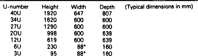
*Smaller cases can be specified as 10E width (38 mm) or 20E width (88 mm)
Smaller units are accommodated in instrument cases, of which the range is much larger. There is a range of cases which will fit the 19 in units from the standard rack systems so that identical chassis layouts can be used either in racks or in the smaller cases. The more general range of casings cover all sizes from a single card upwards, and also down to pocket calculator sizes. Cases can be obtained with carrying handles for enclosing portable instruments, or for bench or desk use. Many casings can be obtained in tough ABS plastics or in diecast metal form. Metal cases are important where RFI/EMI problems are concerned, and for some types of equipment the casing may need to be designed for minimum emission levels.
Some further degree of standardization is emerging, as far as European equipment is concerned, as a DIN standard 43700 for small cases and boxes along with plug-in modules that fit inside.