
Capacitors
A capacitor is an arrangement of conductors that are insulated from each other so that charge can be stored. Imagine two metal plates arranged parallel to each other and separated by air. If we apply a voltage to the plates by connecting them to a battery (Figure 4.1), then one plate will gain electrons and the other will lose electrons. When the battery connections are removed there is no connection between the plates that would allow the electrons to return, and there will still be a voltage between the plates, caused by the fact that one plate is negatively charged and the other positively charged. If the plates are now connected, a transient current will flow until there is no surplus or deficit of electrons on either plate.

Figure 4.1 Two conducting plates separated by an insulator constitute a capacitor, which is charged when connected to a battery.
The total amount of charge that flows when the plates are connected in this imaginary experiment can be calculated by multiplying the amount of current that flows by the time for which it flows, but this is not a simple calculation because the current is not constant, it follows the pattern shown earlier in Figure 1.17. A more useful way of calculating the charge emerges from the knowledge that the quantity:
is always a constant for a particular size and arrangement of plates. This quantity is called the capacitance of the plates, and we can write the equation as:
charge = capacitance × voltage
Q = C × V which can also be written as C = Q/V
What makes this useful is that the quantity we call capacitance can be calculated from factors such as the size and position of the plates, so that if capacitance can be calculated and voltage measured, then the amount of stored charge Q can be calculated.
When modern electrical units were being devised, the unit of charge was, as now, the coulomb, and the unit of voltage is the volt. When coulombs are divided by volts to find a unit of capacitance, this unit, called the farad, turns out to be too large for most of our practical purposes, although capacitors of 1 F can be and are manufactured for specialized purposes. The usual submultiples that are used for the farad are the microfarad (μF), equal to 10−6 F, the nanofarad (nF), equal to 10−9 F, and the picofarad (pF), equal to 10−12 F. For an ever-increasing number of purposes we also need to use the femtofarad (fF), equal to 1O−15 F.
Capacitor behaviour
When DC or pulse waveforms are applied to capacitors, the charge and discharge behaviour is important. In any practical circuit, a capacitor will be charged or discharged through a resistor, and the time that is required for charge or discharge is expressed by the time constant, units seconds, equal to resistance in ohms multiplied by capacitance in farads, as noted in Chapter 1. A more practical set of units uses resistance in kilohms and capacitance in nanofarads to get time in microseconds, so that 1 kΩ × 1 nF = 1 μβ time constant.
• The practical interpretation of time constant, see earlier, is that the charging or discharging of a capacitor through a resistor is reasonably complete in a time equal to four time constants. For example, if a time constant is given as 50 μs, then for this CR connection, charging or discharging would be completed, for all practical purposes, in 200 μs.
For the smaller capacitors connected to any practicable resistor size, this is a short time, but for the larger types the time constant that can be obtained along with a resistor can be quite long. For example, it is possible to use a capacitor as a form of backup against short interruptions of power supply for a low-consumption circuit. If, for example, a capacitor of 1 F, 3 V working, is wired in parallel with an IC which requires a current of 10 μα at 3 V, then this IC constitutes a load of 300 kΩ. The time constant for this circuit is 300 000 seconds, more than 83 hours, and if we assume that the circuit would still operate at a lower voltage (after 63% of the voltage has been dropped) then this would constitute an 83 hour backup. In practice, the leakage current from such a capacitor would be larger than the amount indicated, and such a fall in voltage would not permit the circuit to continue working, but it is possible to maintain a useful voltage level for a drain of 1 mA for periods of an hour or more.
• An important safety point is that the larger capacitors can store a considerable amount of charge at a voltage level which can cause severe shock or burning if the terminals are touched. Even at low voltages, the amount of energy stored by a capacitor can cause destructive sparking, sufficient to melt metal wires, if a charged capacitor is short circuited.
The amount of charged energy is found from:
which gives energy in joules when the units of capacitance and voltage are the farad and the volt respectively. For example, a 5000 μF capacitor charged to 400 V will carry a stored energy of:
This is the amount of energy that would be achieved by a power of 40 W acting for 1 s. When a capacitor short circuited, however, this energy can be discharged in a fraction of a second, and any brief release of such a substantial amount of energy can be very destructive. It can also be painful if it discharges across you, and possibly fatal if you take the discharge of a large capacitor through a path that crosses the heart.
When the voltage across a capacitor is continually varied, the capacitor will be continually charged and discharged, so that there will be a flow of electrons to and from the plates. This flow constitutes a current so that for an applied (sine-wave) alternating voltage there will be an alternating current flowing, and the current will be proportional to the voltage, just as the current through a resistor is proportional to the voltage across it. We can define a quantity called reactance which is analogous to resistance in the formula:
Where V and I are AC values. However, the similarity cannot be taken too far. The reactance of a capacitor is not constant, and there is a phase difference of 90° between current and voltage (see Chapter 1). We could, in fact, draw up an alternative definition of a capacitor as an electronic device that permits the flow of signal current but not DC, and creates a 90° phase difference between voltage and current, with current leading voltage.
Capacitor construction
The simplest type of capacitor is the parallel-plate type, using air as its insulation between the plates. If any solid or liquid insulator is placed between the plates, the capacitance of the arrangement is increased, and the factor by which the capacitance is increased is called the relative permittivity of the material between the plates. Figure 4.2 shows the formula which can be used to calculate the capacitance of this arrangement. This uses a quantity called the permittivity of free space which is a universal constant.

Figure 4.2 The formula for capacitance of a parallel-plate capacitor. The quantity ![]() r is the relative permittivity of whatever insulating material is placed between the plates.
r is the relative permittivity of whatever insulating material is placed between the plates.
Capacitors for low values, a few pF, can be constructed in parallel plate form, although the use of air spacing is unusual except for special-purpose units used for radio transmitters or for calibration purposes. The way that the capacitor behaves, as well as the value of capacitance, is then considerably affected by the material, called the dielectric which is placed between the plates. The area of plate which would be required to make a capacitor of more than a few microfarads in this form is impractical, and all the other shapes of capacitors that are familiar in electronics represent methods of reducing the physical size of the capacitor and yet increasing the amount of capacitance. This process is assisted by the fact that decreasing the distance between the plates (or other conductors) increases the amount of capacitance between them. At the same time, the amount of space that would be needed to accommodate plates of large area can be greatly reduced by folding the plates or by rolling them into a cylinder. Whatever method of construction is adopted, it is always much more difficult to achieve close tolerances with capacitors than with resistors.
We shall return to the physical shapes and construction of capacitors later, but we need to look further at the basic design and how the use of a dielectric affects the behaviour of a capacitor. The obvious effect for which the dielectric is chosen is its value of relative permittivity, which will assist considerably in achieving the value of capacitance that is required. By its definition, relative permittivity must be a positive quantity greater than unity, and values for some solid materials are shown in Table 4.1. Most insulators have values of relative permittivity which are in the range 2 to 5, but there are several types of ceramics which have extraordinarily high values of 100 or more. This makes it possible to use these materials to manufacture capacitors of very compact dimensions, but the high value of permittivity is obtained at the expense of other features. Liquids, not shown in the table, can have even higher permittivity values; an example is Thiokol with a value of over 2000.
Table 4.1
Relative permittivity values for various selected materials. The values of relative permittivity are seldom large
| Material | Value of |
| Vacuum | 1.000000 |
| Air | 1.00004 |
| Aluminium oxide | 8.8 |
| Araldite resin | 3.7 |
| Bakelite | 4.6 |
| Barium titanate | 600–1200 |
| Magnesium silicate | 5.6 |
| Nylon | 3.1 |
| Polystyrene | 2.5 |
| Polythene | 2.3 |
| PTFE Teflon) | 2.1 |
| Porcelain | 5.0 |
| Quartz | 3.8 |
| Titanium dioxide | 100 |
• Thiokol is a health hazard – you must not open a capacitor that contains Thiokol, and care is needed to avoid any error such as an overload that would burst the capacitor open.
One of the most obvious of the other features of the dielectric material is that it constitutes the insulation between the plates of the capacitor. The insulating properties of the dielectric will control the amount of current (which must be very small) which will leak between the plates when the capacitor is charged, and will also determine the dielectric strength in terms of resistance to sparking between the plates. Sparking inside a capacitor can cause damage, and although some types, notably metallized polyesters, are self-healing to a remarkable extent, others will be totally destroyed by sparking.
The leakage of the capacitor, in terms of DC leakage current, is determined by the resistivity of the dielectric. Since the dielectric is always used in the form of a large area and a thin film, only materials of very high resistivity are suitable. Suppose, for example, that we were using a dielectric of relative permittivity 5 and thickness 0.02 mm to make a 0.01 μF capacitor. From the capacitor formula (Figure 4.2), we can calculate the area of the dielectric as 4.5 × 10⁻³ square metres. Now if the material that we use as a dielectric also has a resistivity of 107 μm, which would be a respectable value for a material used for most other purposes in electronics, then the resistance of the dielectric film would be about 45 kΩ. This is unacceptably low for such a capacitor, and we would normally expect a value of resistance of the order of 1000 MΩ. This points to the dielectric requiring to have a resistivity which is at least 22 000 times greater than that of this example. We would not normally consider a value of resistivity of less than 1011 Ωm as being suitable, and for the smaller value of capacitance even this would not be acceptable. Values of the order of 1014 to 1017 Ωm can be obtained using modern plastics and also the ceramics materials that have been used for these purposes for a considerable time. High-quality capacitors can display a dielectric resistivity of 1018Ωm.
DC resistance, however, is only one aspect of capacitor efficiency, one which determines for how long a capacitor can retain a charge. If a dielectric contains any charged particles, or if its atoms can have electrons dragged away by the electric field that exists across the dielectric, then when an AC signal is applied across the dielectric there will be some dissipation. In a perfect dielectric, this movement of particles would be frictionless; whatever energy was needed to move the particles out of position would be returned when they moved back. Most practical dielectric materials are surprisingly close to perfection, but for some purposes we need to know a dissipation factor, which is defined as:
and which for all practical purposes is equal to the power factor for the dielectric, the cosine of the phase angle, φ. The dielectrics that are in common use have dissipation factors which are in the range 0.01 to 0.001.
A further complication is that both relative permittivity and dissipation factor will vary with the frequency of the signal that is applied to the capacitor. The relative permittivity value will decrease as the frequency is increased, and for many materials the decrease is quite small, but suddenly increases at a very high frequency. Values of relative permittivity are usually taken at frequencies of 50 Hz, 1kHz, 1 MHz, 100 MHz, 3 GHz and 25 GHz, although only a few materials are suitable for use at 25 GHz. Several materials exist in which the change of relative permittivity is both small and continuous, with no sudden changes.
The change of dissipation factor as frequency is changed is quite different. The change is greater, and for several types of materials it has a peak around one frequency, a resonance frequency. The relative permittivity will also exhibit a sudden change around this frequency, and the frequency at which this peak occurs is considerably affected by the ambient temperature. For a few materials, the dissipation factor is highest for low frequencies because the materials contain ions which are slow moving and which do not contribute to dissipation when the voltage across the material reverses at a high frequency. An ideal dielectric would have no peaks or other discontinuities in a graph of dissipation factor plotted against frequency.
The other aspect of the insulation of a dielectric is the dielectric strength, which is expressed in terms of the maximum electric field that can be applied to the material. The unit of electric field is the volt per metre, but for the large fields that exist across dielectric materials, units of kilovolts per metre are more suitable. Old tables show this in terms of volts per mil (thousandth of an inch) or as volts per millimetre. Figure 4.4 shows the conversion factors and a few examples of dielectric strength in terms of volts per mil and kilovolts per metre units. The range of dielectric strength is from 19 500 kV/m to 200 000 kV/m for typical dielectrics, and this figure determines the maximum working voltage (or the peak voltage) that can safely be applied to the capacitor. In general, the working voltage will be considerably lower than the value which would subject the dielectric to its rated dielectric strength.
Table 4.2
Converting between units of electric field as volts per mil and kilovolts per metre
| From | To | Multiply by |
| V/m | V/mil | 0.0000254 |
| kV/m | V/mil | 0.0254 |
| V/mm | V/mil | 0.0254 |
| V/mil | V/m | 39370 |
| V/mil | kV/m | 39.37 |
| V/mil | V/mm | 39.37 |
The effect of temperature on a dielectric material will be to alter the physical dimensions, alter the resistivity and the dielectric strength, alter the relative permittivity and alter the dissipation factor and the frequency of the peak of dissipation factor (if there is a noticeable peak). The effects that alter capacitance can be measured by a temperature coefficient of capacitance which is defined in the same way as the temperature coefficient of resistance as:

Figure 4.4 Stacking metallized plates together to form a larger capacitance value with alternate plates connected.
and will be quoted in parts per million per degree Celsius. This temperature coefficient can be positive or negative, and negative values are fairly common. A few dielectrics can cause their capacitors to have very large negative values of temperature coefficient. Some capacitor types have such large values of temperature coefficients that they are quoted as percentage change per degree Celsius rather than parts per million. Polystyrene capacitors, now obsolete, suffer from excessive drift at temperatures above 75°C.
Finally, another effect of the dielectric is remanent charge or soakage, as mentioned earlier and dealt with in more detail in the following pages.
Quoted parameters
The quantities that are quoted for the performance of a capacitor are related to the method of construction and to the choice land methods of preparation of the dielectric, but it is very unusual to see quantities such as dielectric strength quoted. The capacitance value, maximum rated voltage and tolerance of capacitance value are the most important parameters, and tolerance values are invariably higher for capacitors than for resistors. Tolerances of 10% and 20% are normal, with close-tolerance components of 5% to 2% frequently used, and tolerances of 1% and 0.5% available for special purposes. The range of values is almost as vast as that for resistors, ranging from a few picofarads to 3F3 or more, a range of around 1012 from lowest to highest.
The other parameters that are quoted depend on the type of capacitor, because electrolytic capacitors (see later) cannot be judged by the same criteria as other types, and for the moment we will concentrate on the non-electrolytic types. After value and tolerance, the most important factor is working voltage, and in this respect it is usual to quote both a DC and an AC working voltage – the AC voltage rating is always lower because quoted AC voltages are RMS and it is the peak voltage that affects the stress on the dielectric of a capacitor.
These voltage ratings have a very important effect on reliability. Taking DC ratings first, the rating is quoted for a working temperature which is usually in the range 70°C to 85°C, and substantial derating is needed if the capacitor has to be used at temperatures outside this working range. The maximum rated voltage is selected so as to provide a reasonable working life, and the figure of acceptability is usually that of one failure per 105 working hours. If the actual working voltage is significantly lower than the rated value, the reliability of the capacitor may increase considerably because there is little likelihood of a transient overload exceeding the maximum permitted value. You should not, however, take such an improvement for granted.
The value of working voltage that is chosen is well below the voltage value that would represent the dielectric being subjected to the maximum allowable field (dielectric strength value), and some capacitors can withstand brief voltage peaks that are considerably higher than the maximum continuous working voltage. Only these capacitors that are rated to accept such peaks should be subjected to peak voltages, however, because the effect on the life of any other types of capacitors can be unpredictable.
AC ratings of working voltage are considerably more complicated than the DC ratings. There is a common belief that any capacitor that is rated for 240 V AC can be safely wired across the supply mains, but this is quite definitely not so, and only capacitors which are specifically stated as being suitable for this purpose (mains filtering capacitors) should ever be used on mains supplies. Quite apart from any other consideration, a capacitor wired from mains live to mains ground constitutes a leakage to ground, and can cause sensitive ground-leakage contact breakers (ELCB) to open. They also constitute a hazard to operators if there is a fault in ground wiring, since the local ground (metal cabinets, for example) will be live through the capacitor connection. For this reason, the capacitors that are used for mains filtering are of low capacitance value and are of a construction that permits continuous application of power voltage levels and frequency. Where larger values are used, a self-healing type of dielectric will be used so that any breakdown of the capacitor will be momentary only and will not lead to a low-resistance type of failure.
The AC voltage rating of a capacitor is determined by a number of factors. For low frequencies, the voltage rating must be low enough to avoid failure of the dielectric, so that the value has to be considerably lower than would be indicated from the dielectric strength of the insulator. At the higher frequencies, the dissipation loss becomes more important, because it can cause the temperature of the capacitor to rise to a level at which the voltage ratings are no longer applicable. Any capacitor which is to be used for RF voltages at low impedances (so that current could be high) or for pulses with a high repetition rate will have to be derated for working voltage, and manufacturer’s advice should be sought unless a capacitor type specifically states its suitability for such purposes.
In many cases, the specification will provide for use with pulses whose peak amplitude does not exceed the DC rating of the capacitor, but with a stated limit on the rate-of-change of voltage. This might be, typically, 5V/μs or a subminiature polyester type (see later), which will restrict its use to applications in which the rates of rise or fall of voltage across the capacitor are comparatively low. Such capacitors could be used, for example, to couple fast-changing signals (because the voltage across the coupling capacitor is small), but not to decouple such waveforms. Care needs to be taken over specifying such capacitors in digital circuitry where fast pulses were present.
A perfect capacitor would dissipate no energy, since it has no resistance. Real capacitors come remarkably close to perfection, nearer than any other electronic component, but there is always a measurable amount of dissipation. This can be shown in an equivalent circuit as a series resistance, usually of a very small value. The value of this equivalent series resistance is not constant, and for most capacitor types its value will increase as the operating frequency is increased. The value of equivalent series resistor (ESR) is quoted only for electrolytics, for which the resistance is certainly not negligible. In addition, the ESR value is frequency sensitive.
Where any loss factor is quoted for other capacitor types, it will usually be as a power factor or dissipation factor (usually 0.001% or less), meaning the fraction of the volt-amperes (AC volts multiplied by AC amperes) across the capacitor which represent real watts.
Temperature range and temperature coefficients
The temperature range for a capacitor is determined entirely by the type of dielectric that is used. Many capacitors make use of plastics materials, so that the temperature range must be such that the material is used well below its melting point. In addition, several types of plastics materials undergo serious changes in form at very low temperatures, becoming brittle and even cracking.
The temperature coefficients of capacitors can be negative (which is more common) or positive, and a few types can have very large temperature coefficients, although values of ±200 ppm/°C are usual. For some applications of capacitors, such as decoupling, temperature coefficients are almost irrelevant and tolerances are not particularly important either. The most critical applications are for capacitors which form part of a tuning circuit, where a large temperature coefficient could cause mistuning to occur as the temperature changed. Modern oscillator circuits would normally use some form of automatic control, but careful selection of tuning capacitors is also necessary to prevent the tuning from falling out of the range of the automatic controls because of variations in capacitance of a fixed capacitor.
Voltage remanence (soakage)
An effect which has been known for many years, but which has not always been of great importance, is that of voltage remanence, also known as dielectric absorption or ‘soakage’. This is an effect which could be demonstrated quite well on the old-fashioned Leyden jar type of capacitor. When such a capacitor is fully charged, it can be discharged by a spark-over, but after a short time, another spark discharge is possible, and sometimes a third. The explanation is that the energy of a charged capacitor exists as a strain in the dielectric – literally a mechanical strain because electrons and nuclei are being pulled out of their normal positions.
The short circuiting of a capacitor allows these particles to return, but in some types of material the return takes longer than the time of a short circuit, and the voltage across the capacitor builds up again if the capacitor is left open circuit. Some modern types, notably polystyrene, NPO ceramics and polypropylene dielectric types, have almost negligible soakage, and can be specified for uses, such as sample-and-hold circuits, in which this factor is of vital importance. The old oil-filled paper type, by contrast, suffers from this effect and must be handled with care.
One effect of this is that any capacitor which is used to smooth a high-voltage supply should be handled with extreme care and should preferably be kept short circuited all the time it has to be handled. Another aspect is the selection of the auto-zero capacitor on digital voltmeters. This capacitor is shorted at intervals to zero the voltage input to the counting circuit, and a voltage remanence can cause the zero point to be incorrect, with the remanent voltage being added to the measured voltage. Careful selection of the capacitor is needed for such circuits, and for any circuits in which a capacitor may be shorted and then any voltage across its plates measured. Manufacturers of capacitors will advise on suitable types, but the remanence is seldom mentioned in specifications. Capacitors which use Mylar dielectric are likely to have higher values of remanent voltage than capacitors which use traditional mica, ceramic, or paper.
For a full discussion of this problem, along with descriptions of test circuits, see the website:
Voltage-variable capacitance
Any semiconductor junction will contain a depletion region of nonconducting semiconductor between the two conducting regions. Because of the structure of a semiconductor junction, the effective width of this depletion layer is not constant; it increases as the reverse bias on the diode is increased, so that the capacitance across the diode decreases as the bias is increased. Diodes that have been prepared so as deliberately to exploit this effect are known as varicap or varactor diodes.
Varicap diodes are classed as diodes rather than as capacitors, but since their uses are invariably as capacitors it seems reasonable to include them here. In a typical circuit (Figure 4.3), the varicap diode is made part of a tuned circuit, and is connected in series with an isolating capacitor so that the DC bias voltage can be applied through a large-value resistor. The voltage that is used to control the capacitance of the diode can be supplied direct from a potentiometer for hand-tuning (eliminating the use of a variable capacitor of the mechanical type) or from a phase-sensitive detector circuit whose DC output will be proportional to the deviation from a set frequency. This latter use is the familiar AFC type of circuit.

It can be surprisingly difficult to obtain specified types of varicap diodes, because they do not appear in many components catalogues, and are often supplied by semiconductor manufacturers to special order only. The main reason is that these are seldom components that are replaceable in servicing work, and in the applications such as TV tuners, the varicap diode forms part of a circuit whose mechanical layout is critical and which is usually serviced by complete replacement of the module. In some circuits, ordinary silicon diodes can be used in place of specified varicaps.
• A varicap diode can also be used as an active component in a parametric amplifier circuit. Details are beyond the scope of this book, but briefly, amplification is achieved by altering the diode capacitance in synchronism with the applied waveform. The effect is analogous to the way that a child on a swing can increase the amplitude of swinging by making synchronous leg movements.
Capacitor types
The names that are used for types of capacitors are the names of the dielectric materials, because the performance of a capacitor is so closely tied to the type of material that is used for its dielectric. Ceramic covers any of the materials which consist basically of metal oxides that have been fused at very high temperatures; typical raw materials are alumina (aluminium oxide) and titanium oxide. Mica is a natural material which splits into plates that can be remarkably thin; its main form is the mineral muscovite, or ruby mica. When this material is split into plates, the plates often have a silvery appearance (caused by an air film between the remaining plates) so that these are called silver-mica. This has caused considerable confusion because the coating of mica sheets with silver creates a composite called silvered mica.
Because of the natural shape of the raw material, mica is used to make capacitors which are of plate shape, circular or rectangular. Ceramics can be formed to any suitable shape, including plates and tubes, so that the range of capacitor shapes is greater for ceramics than for micas. Whichever of these two insulator types is used, the method of forming the capacitor is to deposit a metal layer on each side of the dielectric. This is easiest when the material is in plate form, and the deposition of metal can be carried out by chemical methods (a traditional method which is particularly easy for depositing silver) or by evaporation or sputtering. The metal layer has to be kept clear of the edges or wiped from the edges so as to avoid short circuits or potential spark-over points. Connecting wires can then be soldered to the metal layer, and the whole capacitor covered with an insulator which can be plastic or another ceramic material.
Tubular ceramics are formed in the same way as plate types, but the metallization process is considerably more difficult and only a chemical method can be used to put a coating inside the tube. Connection to this coating is also more difficult, but the small volume of the tubular type can sometimes be an advantage so that this type of capacitor has been used for many decades, although it has now disappeared from many catalogues because it can be made only in the smallest capacitance sizes, for which there are many other options. The plate form of capacitor has the considerable advantage that metallized plates can be stacked together to increase the capacitance (Figure 4.4), for very little increase in bulk.
Mica capacitors can be made in single-plate form or with stacked plates. In the past, mica plate capacitors have been made using tinfoil laid between mica plates, or with the plates held together using metal eyelets. These older forms are now obsolete, and the only remaining type is the silvered mica construction which has layers of silver deposited on to the mica, whether the capacitor uses a single plate or multiple plates. The silvered mica type of capacitor has the best combination of electrical, thermal and mechanical properties that can be found for a capacitor of low value.
Natural mica has a relative permittivity value of around 5.4, and this value is maintained up to very high operating frequencies, certainly as far as 1 GHz. The dissipation factor is very low at frequencies of 1 kHz upwards, of the order of 0.0003, although at 50 Hz the dissipation factor is about 0.005 because of the presence of ions in the material (which causes the ruby colour of the natural mineral). The dielectric strength is quite astonishingly high, of the order of 150–180 kV/mm, and this is due to the plate form of the material. The structure of mica is of flat molecules of aluminium potassium silicate which bond together into sheets which are ultimately one molecule thick. There is no natural conduction path across these sheets, because the distance between sheets is much greater than the distance between molecules along the sheet, so that any conductivity has to be along the sheet rather than from sheet to sheet. Even the thinnest slices of mica that we can cut consist of many sheets, so that the insulation and the dielectric strength are unrivalled by any material in which the molecules are arranged in a three-dimensional structure.
The volume resistivity of natural mica is 5 × 10¹⁵Ωm, which is not the highest of values but which is an average value that does not take account of the enormous differences that are caused by differing directions of measurement. A value of resistivity which is taken in a direction along a sheet of mica will be much less than a value measured between sheets, and the quoted value is an average. Mica is an example of an anisotropic material, one whose physical attributes will vary according to the direction in which a length is taken. All crystalline materials are anisotropic and materials which form flat sheets, like mica, are very noticeably so. This property is not confined to minerals and crystals – wood is an example of a very well-known anisotropic material in which the strength depends on the direction of the grain.
The temperature coefficient of a silvered mica capacitor is positive, and is in the region of +50 ± 50 ppm/°C, not so low as typical ceramics. The larger values of capacitance provide the lower values of temperature coefficient. Manufactured silvered micas are available in the range 2.2 pF to 1OOOOpF (10 nF), and the usual encapsulation is with wax coated in a ceramic cement. The normal working temperature range is from –40°C to +80°C (some to +150°C or more), with a power factor of 0.002 and insulation resistance of around 1010 Ω. Working voltage is usually 350 V maximum, and this rating includes pulse operation.
Silvered micas are now expensive in the UK as compared to other capacitor types (this is not true in the USA), but their combination of parameters is unequalled by any other type, so that applications which call for the highest possible stability must specify these capacitors. Typical applications are tuned circuits and filters for which the stability of frequency is all important. Because of their physical shape, micas have a very low self-inductance, so that their resonant frequency is very high, and the low loss (very low equivalent series resistance) makes the effective Q, value (ratio of reactance to resistance) also very high.
All capacitors have a value of self-inductance which is low for the low-capacitance values, but fairly high for some wound foil types. As a result, for each value of capacitor there will be a resonant frequency when the self-inductance is in series-resonance with the capacitance. At this frequency, the capacitor has its minimum impedance, and above this frequency the impedance will be more predominantly inductive. The Q,-factor for the capacitor will also be a minimum at the resonance frequency. The physical shape of silvered mica capacitors makes the self-inductance very low, particularly when the capacitors are made in a form suitable for surface mounting (see Chapter 8). Large-value ceramic capacitors and foil types (other than the extended foil types) have comparatively low values of self-resonance.
Ceramic capacitors are, in contrast, very often specified in situations where loss is of little importance. Unlike mica, the ceramics that are used for capacitors are artificially manufactured, although from natural materials. The traditional materials such as magnesium silicate and aluminium oxide have been supplemented by others such as barium titanate and titanium dioxide, and manufacturers tend to use mixtures whose composition and processing are not revealed. Most manufacturers now quote standard specification letters/numbers rather than the precise materials.
Of these standards, the old established N750T96 bears the 750 number because this is its temperature coefficient when formed into a capacitor, and the N signifies that the coefficient is negative. A corresponding N150 material is also available, but the most stable capacitors are manufactured from COG materials (formerly known as NPO), with zero temperature coefficient and low soakage. All of these types have low loss characteristics and have replaced silvered mica for critical applications.
Many other types of ceramics, particularly those with a high titanium content, have very high permittivity values, as high as 6000 in some examples. Unfortunately, many of these ceramics are also highly anisotropic in a very undesirable way – the value of relative permittivity alters when the applied electric field is altered, so that the capacitance value is voltage variable. Materials such as barium titanate are, in fact, piezoelectric, meaning that the dimensions of the whole crystal will alter as the voltage across the material is altered. A few materials have high relative permittivity that is combined with reasonable stability, and one of the specifications for such capacitors is X7R/2C1. For less demanding applications, where a variation of capacitance value with applied voltage or temperature can be tolerated, the specification Z5U/2F4 can be used.
For some types of ceramic capacitors, the dissipation factor can be substantial, of the order of 0.15% (0.0015) for the C0G/NP0 type, rising to 3% (0.03) for the Z5U type, so that the equivalent series resistance of these types is comparatively high. The C0G/NP0 type, nominally of zero temperature coefficient, can have values of ±30 ppm/°C, which is acceptably low. The other types have much higher temperature coefficients which are variable so that the value of temperature coefficient will itself vary as the temperature is changed. For these capacitors, it is more usual to replace temperature coefficient by a maximum-change percentage. For example, if a ceramic capacitor has the figures +56%, –35% given in place of temperature coefficient, this means that the maximum change that can be expected at the extremes of the temperature range will be of these percentages. The rated temperature range for the X7R material is –55°C to +125°C and for the Z5U is –10°Cto +85°C. Typical maximum changes over these temperature ranges are +15% to –25% for X7R and +56% to –20% for Z5U.
The applications for which ceramic capacitors can be used must therefore be tailored to the type of dielectric that is used. Capacitors, mainly in the 10–100 pF range, that use the NPO dielectric are suitable for general (usually low-voltage) purposes, including oscillator tuned circuits, timing circuits and filters whose specifications do not demand the use of silvered micas. The more stable of the high permittivity materials, X7R, is specified for values up to about 0.1 μF, and these capacitors are used in bypass and decoupling applications, less demanding filtering circuits, timing, and for coupling applications in which the temperature stability is less important. The Z5U dielectric has the highest range of relative permittivity values and is used to obtain very high capacitance values in the range 0.22 μF to 1 μF. These capacitors are used mainly for decoupling and bypass applications, although they can also be used for coupling in circuits whose time constant need not be stable. The insulation resistance of the smaller capacitance value is of the order of 1011 Ω, but for the larger values a formula 109/C Ω, with C in microfarads, is used to specify resistance.
• Of all ceramic capacitors, C0G/NP0 types alone are suitable for sample-and-hold circuits. These ceramics are available in sizes up to 0.01 μF.
High relative-permittivity disc ceramics are made specifically for decoupling purposes for both analogue and digital circuitry. Most digital circuits generate very sharp pulses as devices switch on and off, and these pulses can be spread by way of the DC power supply lines or bus lines unless suppressed. In most examples, it is necessary to place a decoupling capacitor at each IC, connected between the positive supply line and ground, but on some circuits using low clock rates this can be relaxed to one capacitor for each five ICs. Stability of value is unimportant in such an application, where the important features are high capacitance in small bulk and low inductance.
Modern disc ceramics are well suited to this purpose, with a capacitance range of 1 nF to 100 nF (0.1 μF). These can be obtained as low-voltage types, suitable for digital circuits, and high-voltage types that are used in TV and radar circuitry. Tolerance of value is large, in the range +80% to –200%, and variation with temperature is seldom quoted. Insulation resistance of 1010 Ω is typical. A more specialized shape for digital use is the low-profile DIL type which is of the shape and size of an IC, but flat, with four pins arranged so that two pins will fit into the positive and negative supply positions of typical ICs and the two other pins are dummies. These DIL capacitors can be fitted into an IC mounting position under the IC, so minimizing the inductance of leads, and if necessary can be fitted on top of existing ICs if existing decoupling is inadequate. The pin ranges are for 14-, 16-, 20-, 24-, 28- and 40-pin ICs.
• Note that the older type of disc ceramics had comparatively high self-inductance, making them unsuitable for decoupling in critical applications. The more recent multilayer disc types are much superior.
Ceramic plate capacitors are also used for lead-through (feed-through) capacitors, used for low-pass filtering when a supply cable is taken through a metal panel. Values range from 100 pF to 10 nF, and the combination of series inductance and parallel capacitance can be specified in terms of the decibels of attenuation for high-frequency signals, assuming a standard line impedance of 50 Ω. Lead-through types are not effective for sine-wave signals of less than 10 MHz, but are very useful for digital circuit filtering of supply lines, particularly now that high clock rates of 800 MHz and above are employed in computer circuits. Attenuation values range from 1 dB for 10 MHz/100 pF to 63 dB for 1 GHz/10 nF.
There is also a range of low-permittivity capacitors with negative temperature coefficients, intended for temperature compensation. The principle is that by combining a main capacitor, which has a positive temperature coefficient, in a tuned circuit along with a smaller value which has a negative temperature coefficient, it is possible to cancel the effects of temperature altogether over a reasonable frequency range. As the main capacitor can be a mica type, with a very low positive value of temperature coefficient, only a small value of capacitor with negative temperature coefficient need be connected in parallel; alternatively a large capacitance value can be used connected in series. The dielectrics that are used are the N150 to N750 types, and even the C0G/NP0 type can be used because its temperature coefficient can range from +30 to 30 ppm/°C. Commonly used values range from 2.2 pF to 220 pF, but much larger sizes are available, up to 0.01 μF. Several manufacturers colour code the capacitors in order to indicate what temperature coefficient is applicable.
METALLIZED FILM TYPES
Metallization by evaporation can be applied to materials which are far from being heat resistant, and which would absorb moisture if they were metallized by a chemical method. At one time, paper dielectric capacitors were made using strips of waxed or oiled paper and aluminium foil. These were able to achieve large capacitance values (compared to the silvered mica capacitors that were used at the time) by making use of a large area of dielectric, but the overall size was kept compact by rolling the foils into a cylinder (Figure 4.5). Paper as a dielectric material has now been superseded almost entirely by plastics materials which can be manufactured to much closer specifications, and the aluminium foil has been superseded by aluminium metallized coatings, produced by evaporation. This allows much thinner dielectric films to be used, with the metal in perfect contact with the dielectric, so that higher capacitance values can be achieved in lower bulk, and with better characteristics than ever could be achieved using paper as a dielectric.
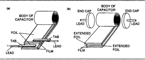
Figure 4.5 (a) The rolled construction used originally for paper capacitors and now for many types of plastic film capacitors; (b) how self-inductance is reduced by making connections to the whole edge of each foil.
• Older capacitors of rolled construction used connecting tabs placed at one end of the foils. This causes the self-inductance to be high, and modern practice is to overlap the foils to either end, so that a metal end-cap makes contact to all of the edge of a foil, Figure 4.5(b).
The plastics that are used are almost as varied as the plastics industry can supply, mainly polyethylene (mainly as polyethylene terephthalate or Mylar) polypropylene, polycarbonate, and polyester, although PTFE (polytetrafluoroethylene), also known as Teflon has also been used, as has cellulose acetate and others. Polystyrene has also been used in the past, but capacitors using this material are no longer in production. None of the plastics materials offers very high values of relative permittivity, particularly polystyrene, so that the reduction in bulk as compared to the traditional paper type of capacitor is due mainly to the use of evaporated metal coatings in place of metal foil.
These evaporated coatings also offer the useful advantage of being self-sealing, in the sense that if a spark-through occurs at a moderate voltage, this will evaporate off some of the thin metal coating and prevent any further conduction. This self-healing effect does not apply at low operating voltages. In place of a fully rolled construction, some plastic film capacitors are available which use interconnected layers of foil or metallizing. These are referred to as multilayered in the UK and as stacked-foil types in the USA; they have the advantage of much lower self-inductance values.
The plastics that are used show considerable variation in performance. The maximum working temperature for many plastics is low, and derating usually has to be applied when temperatures start to approach this limit. In this respect, polystyrene is poor, with a limit of 70°C for most types, although a few types permit use up to 850°C. Polycarbonate types, by contrast, can generally be used up to 100°C with little or no derating, although polyester types are generally rated for a working voltage at 85°C. The temperature coefficients of capacitance are also markedly different, with polyester having a large positive temperature coefficient and polystyrene a smaller negative value. None of the plastics materials has a constant value of temperature coefficient. All of the currently used materials have high insulation resistance values, but the difference between best (polypropylene) and worst (Mylar) can be of the order of 103. Insulation resistance values are often quoted in terms of megohm-microfarads, the product of resistance in megohms and capacitance in microfarads. Thus a rating of 106 MΩ μF means that a 1 μF capacitor will have insulation resistance of 106 MΩ; a 0.01 μF will have resistance of 108 MΩ μF and so on.
The run-of-the-mill Mylar or polyester dielectric capacitor is the tubular axial type encapsulated in epoxy resin, with a typical value range of 0.01 μF to 2.2 μF. These will be used for consumer electronics and for non-critical applications generally, and are available in various voltage ranges, typically 250 V DC (125V AC) and 400 V DC (200 V AC). These working voltages are quoted for a maximum working temperature of 85°C and although a working temperature range of –40°C to +100°C is usually quoted, the working voltage will have to be derated very considerably for temperatures above 85°C. The power factor is not outstanding, of the order of 0.01 maximum, measured at 1 kHz. The temperature coefficient is positive, 500–600 ppm/°C, and the insulation resistance follows a 10 000 MΩ μF rule.
For more critical applications, particularly in computing and industrial electronics, there are miniature versions of the polypropylene film type which are encased with a shrunk-on sleeve. Working voltages of 250, 500 and 750 V DC (half these amounts for AC) are available, but in a restricted range of values between 0.001 μF and 0.047 μF. These working voltages are quoted at 80°C and as usual, will have to be derated considerably at higher voltages within the working range of –55°C to +100°C. The temperature coefficient is the same at 200 ppm/°C as would be expected, and for this particular format, the insulation resistance is quoted as a minimum of 105 MΩ.
Polyester film capacitors are also available in block form. The principles of construction are either multiple layer (stacked), like the larger values of ceramic or mica, or the use of a long strip (as for the rolled type) which is then repeatedly folded rather than rolled. The casing is then moulded round the capacitor, often using epoxy resin at the sealing lines, although some types use a dip coating of epoxy resin for better sealing. All of these capacitors provide large capacitance values in a small space, and can be obtained in sub-miniature forms with voltage ratings of 50 V DC (30 V AC) where space is at a premium.
The miniature dipped-case type is coated with an epoxy resin which is water-repellent, resistant to solvents and flame retarding as well as being an excellent insulator. Capacitance values of 0.01 μF to 2.2 μF are usual, with 20% tolerance (sometimes 10%). Insulation resistance is better than 104 MΩ. Dissipation factor is in the range 0.0075 to 0.015 for frequencies of 1 kHz to 10 kHz. The temperature range is the usual –40°C to +100°C, subject to the usual derating above 85°C. The subminiature versions are intended for low-voltage uses, with an insulation resistance in excess of 2000 MΩ. The commonly used range of values is 0.001 μF to 0.1 μF, all at 20% tolerance, but values outside this range are available. The quoted dissipation factor is a maximum of 0.01. Where pulse use is permitted, the maximum amplitude is usually equal to the DC rated voltage, but the rate of rise or fall is comparatively slow at around 5 V/μs. These capacitors are not suitable for use in circuits where the rate of change of voltage across the capacitor is large.
The encased types of polyester block capacitor cover the value range of 0.01 μF to 2.2 μF, and working voltages of 63 V to 400 V DC, subject to the usual lower AC values, and to derating for high temperature operation. Some types quote temperature coefficients of 300 ppm/°C, others (mainly the lower voltage types) give only the expected range of change as +5%. The larger moulded case types have an insulation resistance of better than 25 000 MΩ; for some of the smaller types this figure can be as low as 15 000 MΩ. Power factor for either range is about 0.01 at 1 kHz.
More specialized types are available for more specialized purposes. The encapsulated polyester block capacitors that are intended for low-voltage telecommunications and industrial applications are made for a rated 30 V, 50 V or 63 V. Since the applications generally call for a working voltage of between 5 V and 20 V, the rating is very conservative, even allowing for any derating for temperature (and rather more derating will be needed for the semiconductors in the circuit). The quoted working voltage is at the usual 85°C with a temperature range of –55°C to +100°C. In the UK, temperature coefficient figures of 200ppm/°C are quoted, although higher figures of the order of 600 to 800 ppm/°C are always quoted in the USA – this difference is puzzling, particularly when the source is probably the same Japanese manufacturer. Insulation resistance follows the rule of 10 000 MΩ μF.
The multilayer form of construction can be used to create very compact block shapes in a range of high-performance capacitors which have good self-healing properties. Values range from 0.01 μF, 400 V to 2.2 μF, 100 V with 10% tolerance. The temperature coefficient is 200 ppm/°C, with the working voltage quoted at 85°C in a range of –55°C to +100°C. The dissipation factor is 0.01, which is fairly high, but the insulation resistance is better than 104 MΩ. These capacitors are often insulated with only a very thin film of plastic, so that they should not be mounted close to other components nor tightly against the PCB.
One other form of construction for the polyester (or other film) type of capacitor with a rolled construction is as a mains-connected type, often in a steel-cased format. This is used where a large capacitance value is needed, and size/weight factors are less important than non-polarized working. In particular, this refers to connection across the mains for power-factor correction or transient suppression, also for reservoir capacitance use in circuits where electrolytic capacitors cannot be specified. The connection to the outer layer of foil is usually indicated by a stripe on the casing.
One form of these capacitors is the steel-encased block type rated at 600 V DC or 250 V AC. These have replaced the oil-impregnated paper types that used to be common in such applications. The casing is not electrically connected, and is present only to ensure containment in the event of an explosive fracture of the capacitor due to catastrophic overload. The capacitor is mounted by using a metal clip or solder lugs, and it should be preferably mounted to a metal chassis rather than to a PCB. The rated voltage is at 70° C and considerable derating may be needed – a 600 V DC rating at 70°C becomes 400 V AC at 85°C, with pro rata changes in the AC rating. Metallized Mylar capacitors should not be operated at low voltages.
The smaller block types are intended for connection across a mains supply in filter circuits, usually for RF suppression, rather than as any part of a smoothing or power-factor circuit. The 250 V AC rating is for a working temperature of 75 °C. These are available in two classes. Class X working allows for direct connection across mains leads, but not if failure of the capacitor could cause risk to electric shock to an operator by, for example, making a metal panel live to mains. The class Y capacitors are rated as being suitable for connection across the mains in more dangerous situations in which capacitor failure could cause danger of shock (BS 6201: Part 3 in the UK). The class X types can use polyester film and the class Y types normally use polypropylene film; the metallized polyester type are inherently self-healing at other than low voltages.
The class X capacitors are encapsulated first into epoxy resin and then into flame-retardant casings, and have values of 0.01 μF to 0.47 μF. The working voltage is 75°C, and the derating factor is 1.25% of voltage per °C above 75°C, subject to the absolute temperature range of –55°C to +100°C. The quoted temperature coefficient is 300 to 400 ppm/°C, and the power factor is better than 0.008 at 1 kHz. The insulation resistance is obtained from 10 000 MΩ μF (minimum 30 000 MΩ).
The class Y capacitors come in a value range of 0.0022 μF to 0.047 μF, and can also be used in AC circuits other than mains circuits operated at low frequencies at voltage levels up to 500 V rms. The dissipation factor is better than 3 × 10⁻³, and the temperature range is –55°C to +85°C at full ratings. The insulation resistance is shown as 5000 MΩ μF, subject to a minimum of 15 MΩ. A pulse rate or rise or fall rating is also specified; 125V/μs for the smaller capacitance sizes and 50 V/μs for the larger values.
Polystyrene capacitors are obsolete now that better materials are available. The main drawback of polystyrene was the restricted temperature range of –40°C to +70°C, with the working voltage often being quoted at 25°C. There is also a marked discrepancy between DC and AC working voltages, so that a capacitor which is rated at 160 V DC is often rated as only 40 V for AC. The tolerance can be surprisingly tight (at a price), of the order of 2.5%, and the value range is of the order of 10 pF to 10 nF. Power factors are very low, less than 0.001 at 1 MHz, and the temperature coefficient is in the range –70 to 230ppm/°C. The insulation resistance is very high, of the order of a million megohms, giving a very long time constant for leakage.
The remaining film-type capacitors are those using polypropylene and polycarbonate. Polypropylene has the lowest power factor ratings of all the plastic films, along with very high dielectric strength which makes it possible to construct capacitors of high voltage ratings. Pulses with high rise or fall rates can be applied, and the material has a consistent value of relative permittivity that does not fall for high-frequency signals. Propylene is used for a full range of capacitors of voltage ratings from 50 V to 1500 V DC, in capacitance values of 0.001 μF to 0.47 μF. These working voltages are quoted at 70°C and the derating factor is 50% for operation at 100°C, the maximum temperature of operation (minimum is –55°C). The temperature coefficient is negative, 200ppm/°C, and the insulation resistance is very high, better than 105 MΩ with a power factor of less than 10−3 at 10 kHz. For the 1000 V range, the permitted pulse rate of rise or fall is 1800 V/μs, a rate that can be bettered only by mica and some ceramic types. For the 1500 V capacitor range, the permitted pulse rate of rise/fall is 950 V/μs.
Polycarbonate material is considerably less easy to obtain in thin-film form and so is found only where its superior characteristics demand its use, mainly in military, telecommunications and industrial uses. Polycarbonate types can be in slab form, plastic encapsulated, or for the most arduous conditions, tubular and encased in brass, insulated with epoxy resin. A temperature range of – 55 °C to + 100°C with no derating is specified for the brass-cased types, with a value range of 1 μF to 10 μF. The other varieties can be obtained in a wider range of values down to 0.01 μF. The temperature coefficient can be very low, +50 ppm/°C, and the power factor is better than 0.005 at 1 kHz. Typical working voltage is 63 V DC (45 V AC) for use in low-voltage circuits.
The slab type exists in a larger range of 0.01 μF to 4.7 μF, and in voltage ratings from 160 V DC (100 V AC) to 630 V DC (300 V AC), although use on AC mains is not recommended. The working temperature range is –55°C to +100°C, subject to derating above 85°C, with the same minimum temperature coefficient of ±50 ppm/°C. The insulation resistance is a maximum of 3 × 10⁴ MΩ for the formula 104 MΩ pF.
The smaller capacitor types can have their values colour coded rather than printed, although in Europe, it is more common to print value than to use colour coding. A five-band code is used, with the first three bands used for value in picofarads (two significant figures and multiplier). The fourth band is black for 20%, white for 10% tolerance, and the fifth band is red for 250 V DC working and yellow for 400 V DC working. Tantalum electrolytics (see later) are also found colour coded using four bands, but with values in microfarads rather than picofarads and with the fourth band indicating working voltage (but not using the standard number equivalents for the colours).
Electrolytic capacitors
The electrolytic capacitor is a subject by itself, and it has to be treated separately from all other capacitors. The principle is that several metals, notably aluminium and tantalum, can have very thin films of their respective oxides formed on the surface when a voltage is applied in the correct polarity (metal positive) between the metal and a slightly acidic liquid. These very thin films then insulate the metal from the conducting liquid, the electrolyte, forming a capacitor; an electrolytic capacitor. The name comes from the resemblance to an electrolytic (metal plating) cell.
• This same effect causes the problem of polarization of cclls, see Chapter 7.
The most common type of electrolytic capacitor makes use of aluminium foil, which can be etched, dimpled or corrugated to increase the effective area, enclosed in an aluminium can which is filled with a slightly acid solution of ammonium perborate in jelly form. The capacitor is formed by applying a slowly rising voltage to the capacitor, with the foil positive and the case negative until the voltage reaches its rated level and the DC current falls to a minimum, indicating that the insulation is as good as it is ever likely to be. From then on, when the capacitor is used, it must have a DC (polarizing) voltage applied in the same polarity so as to maintain the insulating film. If the capacitor is used with the voltage reversed, the film will be dissolved, removing any insulation and allowing large currents to pass through the liquid, which will vaporize, destroying the can. The electrolyte is usually in jelly form, but the devastation that can be caused by an exploding electrolytic (not to mention the noise) ensures that no one who has achieved this is willing to try again.
The use of tantalum as the metal of an electrolytic allows for a very different form of construction, in which the oxide film is more stable and able to withstand reversals of voltage. Tantalum capacitors (tantalytics) can be used without a steady polarizing voltage, can be run with the electrolyte virtually dry, and have generally better characteristics than the traditional aluminium type of electrolytic. Experience with the use of tantalum has led to the development of ‘dry’ electrolytes for the aluminium type of electrolytic also.
• Tantalytic capacitors should not be used in audio coupling applications in which there is little or no bias voltage.
Because of the very fragile nature of the insulating film, which can be only a few atoms thick, electrolytic capacitors are always liable to have a large amount of leakage, so that leakage current at rated voltage is quoted rather than power factor or dissipation factors. Leakage is often related to the capacitance value and working voltage, and the formula:
Ileakage = 4 + (0.006 × C × V)
is often used, with I in μα, C in F and V in volts. For example, using this formula for a 200 μF capacitor at 12 V gives leakage current of 4 + (0.006 × 200 × 12) = 18.4 μα. Several manufacturers will make use of this formula to quote leakage values. No manufacturer will guarantee an electrolytic to have low leakage value, but the measured values are often surprisingly good if the electrolytic is being operated in reasonable conditions. Bob Pease quotes examples of 500 μF electrolytics with 2 nA leakage at 10 V working.

Many manufacturers also quote a life expectancy in excess of 100 000 hours, at 40°C and rated voltage, for electrolytics, since there is still some prejudice against their use for anything other than consumer electronics. Military applications generally forbid the use of electrolytics, but they are now widely accepted for industrial equipment. Temperature ranges of –40°C to +85°C are often quoted, but considerable derating is needed at the higher temperatures, and there is a risk of freezing the jelly type of electrolyte at the lower temperatures. This is counterbalanced to some extent by an increase in losses as the electrolyte freezes, leading to higher dissipation and subsequent thawing. This, however, is not an effect that you should rely upon. Some types can incorporate vents in order to relieve gas pressure inside the electrolyte.
Electrolytics are used predominantly as reservoir and smoothing capacitors for mains-frequency power supplies, so that their most important parameters, other than capacitance and voltage rating, concern the amount of ripple current that they can pass. For each capacitor the manufacturer will quote a maximum ripple current (typically at 100 or 120 Hz), and also two parameters that concern the ability of the capacitor to pass current, ESR and impedance. The ESR is the effective series resistance in milli-ohms, typically 50 mΩ, for low-frequency currents, and this value may set a limit to the ripple current that can pass; also to the effectiveness of the capacitor for smoothing. The other parameter is effective impedance in mΩ measured at 10 kHz and 20°C, which is used to measure how effectively the capacitor will by-pass currents at higher frequencies. If an electrolytic capacitor is used in a decoupling circuit which is likely to handle a large frequency range, other capacitor types should be used to deal with frequencies higher than 10 kHz, such as a polyester type for the range to 10 MHz and a mica or ceramic for higher frequencies. A useful rule of thumb is to have one electrolytic for five ceramics or discs.
The general-purpose type of electrolytic uses aluminium, often with a separate aluminium casing rated at 1000 V insulation value. The physical form is a cylinder with tag, rod or screw connectors at one end. The capacitance range is generally very large for the lower-voltage units, up to 15 000 μF for 16 V working, but at the higher voltage ratings of 400 V, values of 1 μF to 220 μF are more usual. Many designers avoid the use of an electrolytic at more than 350 V working. The tolerance of value is large (−10% to +50%) and permitted ripple currents range from 1 A to 7 A depending on capacitor size.
Another useful rule of thumb is that you need 1000 μF of smoothing per ampere of DC output, but this is not necessarily satisfactory. Suppose, for example, that a 5000 μF capacitor is used with a 6 V supply at its full rated ripple current of 5 A and has an ESR of 50 mΩ. The sawtooth ripple will amount to 6 V peak-to-peak, with a further 5 × 0.05 V = 0.25 V due to the ESR, almost negligible. The dissipation in the capacitor will also be too high, and in this type of circuit it is better to use several capacitors in parallel.
Smaller electrolytics are made for direct mounting on the circuit boards for decoupling or additional smoothing, and these are cylindrical and wire terminated, either axial (a wire at each end) or radial (both wires at one end). The voltage range can be from 10 V to 450 V, with a working temperature range of –40°C to +85°C (derating advised at the higher temperatures), and with power factors that can be as low as 0.08 and as high as 0.2. The largest range of values, typically 0.1 μF to 4700 μF, is available for the smaller working voltages. The sub-miniature versions have working voltages that range from 6.3 V to 63 V, and with leakage current which is 3 μα minimum, with the larger capacitance units having leakage given by the formula: 0.01 C × V. For example, a 47 μF 40 V capacitor could have leakage of: 0.01 × 47 × 40 = 18.8 μα, but measured values are usually much smaller, as low as 10 nA or even less for modern capacitors.
A specialized wet-electrolyte type is made for the purposes of memory back-up in digital circuits. CMOS memory chips can retain data if a voltage, lower than the normal supply voltage, is maintained at one pin of the chip. The current demand at this pin is very low, and can therefore be supplied by a capacitor for considerable periods. This is not the method that is used for calculators, which use a battery, but for such devices as central heating controllers which must retain their settings if the mains supply fails for a comparatively short period. Typical values for these electrolytics are 1F0 and 3F3. Discharge times range from 1 to 5 hours at 1 mA and 300 to 500 hours at the more typical current requirement of 5 μA, but the high leakage current must be taken into account.
Solid-electrolyte types are now available in the aluminium range of electrolytics. Unlike the traditional type of aluminium electrolytic, these need no venting, and cannot suffer from evaporation of the electrolyte. Also, unlike the traditional electrolytic they can be run for periods with no polarizing voltage, and can accept reverse voltage, although at only about 30% of rated forward voltage at 85°C, considerably less at higher temperatures. Typical sizes are from 2.2 μF to 100 μF, with voltage ratings of 10 V to 35 V at 85°C. Temperature range is –55°C to +125°C, and even at the maximum working temperature of 125°C, the life expectancy is in excess of 20 000 hours. The leakage currents are fairly high, in the range 9 μA to 250 μA, and the ripple current ratings are in the range 20 mA to 300 mA. One important feature is that the specifications place no restrictions on the amount of charge or discharge current that flows in a DC circuit, provided that the working voltage is not exceeded.
TANTALUM ELECTROLYTICS
Tantalum electrolytics invariably use solid electrolytes along with tantalum metal, and have much lower leakage than the aluminium types. This makes them eminently suitable for purposes such as signal coupling, filters, timing circuits and decoupling. The usual forms of these electrolytics are as epoxy-coated miniature beads or tubular axial types. The voltage range is 6.3 V to 35 V, with values of 0.1 μF to 100 μF. The temperature range is –55°C to +85°C. Tantalum electrolytics can be used without any DC bias, and can also accept a small reverse voltage, typically less than 1.0 V. A minimum leakage current of 1 μα is to be expected, and for the higher values of capacitance and working voltage the leakage current is found from the capacitance × voltage factor, subject to the minimum guaranteed value of 1 pA. Power factors in the range of 0.02 to 0.2 can be expected. Care should be taken not to exceed the surge voltage rating, typically 1.3 × rated DC voltage rating.
Variable capacitors
At one time, it would be normal for a catalogue to list variable capacitors of 500 pF maximum or 350 pF maximum in single-, double-or three-gang pattern. Such capacitors, once used in radio receivers, are now available only for replacement purposes and can be quite difficult to find. The reason is the almost universal adoption of electronic tuning methods, making use of voltage-variable capacitors, the semiconductor varicap diodes. The only remnants of the old-style variable capacitors are trimmers.
Trimmers consist of single-turn variable capacitors, using one fixed set and one rotating set of plates, with a solid insulator, usually polypropylene, separating the plates and providing a considerably greater capacitance than would be expected in a small bulk. Capacitance variation depends on the number of plates and size of trimmer, and ranges from 1.4 pF to 10.0 pF and from 5.5 pF to 65 pF. Temperature range is –40°C to +70°C, and the voltage rating is typically 100 V. The dissipation factor is very low, typically 10−9.
Failure mechanisms of capacitors
Capacitors are responsible for a substantial fraction of the failures in service of electronic equipment, with a reliability that is somewhere between that of discrete semiconductors and resistors. It is therefore important to know why capacitors fail and how the reliability of capacitors can be enhanced. This concerns both the designer and the service engineer, because if a unit is known to fail at frequent intervals because of a capacitor problem, the capacitor should be replaced with one that can be expected to have a longer life.
Capacitor failures can be classed as open circuits, short circuits and leakage failures and all three can be caused by the most common of all capacitor problems, internal sparking. Sparking can either evaporate metal contacts, causing an open circuit, or it can penetrate a dielectric, causing shorting. Plastic dielectrics can char under heavy sparking, creating a carbon track which forms a short circuit, although modern plastic dielectrics will permit metal to be evaporated in the usual self-healing mode. Leakage failure is less common, but can be caused by internal short circuit paths or by external paths (around the side of the dielectric).
The main causes of premature capacitor failure are excessive voltage, excessive current or excessive temperature, or combinations of all three. Combinations of parameters can be particularly damaging, because although a capacitor may be rated for operation up to 120°C and for 100 V working, this does not imply that a voltage of 100 V can be used at a temperature of 120°C. Mica and ceramic types are less likely to be affected by running at extremes of their parameters for short periods, but plastic dielectrics have to be treated with much more care, and electrolytics in particular should always be conservatively rated. Sudden charging or discharging can be damaging to capacitors, and is the reason for so many types quoting a maximum rate of rise or fall of voltage.
• The older type of electrolytics used at high voltage levels can fail if they have been out of use for some time and are suddenly subjected to working voltage. This is because the gas film has dissolved, and the recommended procedure is to re-form the electrolytic by gradually increasing the applied voltage to its normal level.
The power factor or dissipation factor for a capacitor is seldom important for DC applications, but when a capacitor is used to handle AC, particularly high-frequency AC, then a poor power factor can cause self-heating because of the current flowing through the equivalent series resistance. Unlike resistors, capacitors are assumed to work at ambient temperature, with no self-heating, and even a small amount of dissipation in a capacitor can be destructive, because the dielectric is also a good heat insulator and will not permit the heat to be easily dissipated. Because of this, the internal temperature can rise well above the external temperature, causing failure. As usual, the plastic dielectric types are particularly susceptible because of the low melting point of most plastics. For electrolytics, the internal resistance at normal working temperature is known, and the dissipation is more easily calculated for the maximum ripple current. Note, however, that when electrolytics are used at unusually low temperatures (but within their permitted range), the internal resistance can rise considerably, causing much greater dissipation, and hence overheating which is often localized and will lead to failure.
One of the prime causes of capacitor failure is locating capacitors near high-dissipation components such as resistors or, in some cases, transformers or chokes. The permitted ambient temperature around capacitors is lower than for resistors, and a good rule is never to subject capacitors to temperatures that would be unsuitable for semiconductors. Assuming that the temperature around capacitors can be controlled, the other factors are then voltage, particularly surges, and current, both of which are reasonably predictable from a knowledge of the circuit in which the capacitor will be used.