
Transducing components
A transducer is a device that converts energy from one form into another and in the broadest sense even a resistor qualifies for this description since it converts electrical energy into heat energy. We normally reserve the term of transducer, however, for the components in which the conversion is desired and used, and in this book we are concerned only with passive transducers that require no energy supply other than the energy that is being converted. Many of these devices are specialized, and only a broad outline of some of the most common devices will be dealt with in this book for reasons of space. The reader should consult a more specialized text for further information.
The main features of transducers, as far as their status as passive components is concerned, are their sensitivity or efficiency, their electrical impedance, their linearity and their bandwidth or frequency response. Sensitivity or efficiency refers to the fraction of input energy which is converted to output energy, and for many transducers this can be very low, of the order of a few per cent. The percentage efficiency is often masked by quoting the sensitivity in terms of the amount of output per unit input. Since the units of input and output will not necessarily be the same, the efficiency of conversion is not obvious.
The electrical impedance of transducers can range from a fraction of an ohm to many megohms, and it affects the type of connections that can be made to the transducer. In addition, if the transducer has an electrical output, the impedance level usually goes hand in hand with the typical electrical output level. Linearity means the extent to which the output is proportional to the input, so that a perfectly linear device would have a graph of output plotted against input that would be a straight line.
Some of the earliest transducers to be used in electronics were the electro-acoustical type, microphones and loudspeakers. A sound wave is the waveform caused by a vibration which will, in turn, cause an identical vibration to be set up in any material affected by the sound wave. The transducer for sound energy to electrical energy is the microphone, and microphone types are classified by the type of transducer they use. The characteristics of a microphone are both acoustic and electrical. The overall sensitivity is expressed as millivolts or microvolts of electrical output per unit intensity of sound wave, or in terms of the acceleration produced by the sound wave. In addition, though, the impedance of the microphone is of considerable importance. A microphone with high impedance usually has a fairly high electrical output, but the high impedance makes it very susceptible to hum pickup, either magnetically or electrostatically coupled. A low impedance is usually associated with very low output, but, provided that the layout and shielding are both good, hum pickup is almost negligible.
Another important factor is whether the microphone is directional or omnidirectional. If the microphone operates by sensing the pressure of the sound wave, then the microphone will be omnidirectional, picking up sound arriving from any direction. If the microphone detects the velocity (speed and direction) of the sound wave, then it is a directional microphone, and the sensitivity has to be measured in terms of direction as well as amplitude of sound wave. The microphone types are known as pressure or velocity operated, omnidirectional or in some form of directional response (such as cardioid). The acoustic construction, rather than the type of transducer, determines whether a microphone is directional or not.
Microphone types
The principle of the moving-iron (variable reluctance) microphone is illustrated in Figure 8.2. A powerful magnet contains a soft-iron armature in its magnetic circuit, and this armature is attached to a diaphragm. The magnetic reluctance of the circuit alters as the armature moves, and this in turn alters the total magnetic flux in the magnetic circuit. A coil wound around the magnetic circuit at any point will give a voltage which is proportional to each change of magnetic flux, so that the electrical wave from the microphone is proportional to the acceleration of the diaphragm. The linearity of the conversion can be reasonable for small amplitudes of movement of the armature, very poor for large amplitudes. Both the linearity, and the amplitude over which linearity remains acceptable can be improved by appropriate shaping of the armature and careful attention to its path of vibration. These features depend on the maintenance of close tolerances in the course of manufacturing the microphones, so that there will inevitably be differences in linearity between samples of microphones of this type from the same production line. The output level from a moving-iron microphone can be high, of the order of 50 mV, and the output impedance is fairly high, typically several hundred ohms. Magnetic shielding is always needed to reduce mains hum pickup in the magnetic circuit.
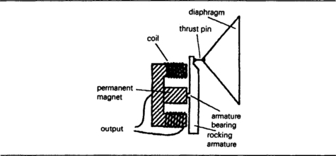
Figure 8.2 Moving-iron microphone principle. Movement of the diaphragm alters the magnetic circuit, inducing a voltage in the coil.
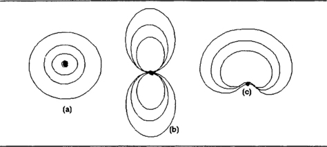
Figure 8.1 Simplified response curves for microphone types: (a) omnidirectional; (b) velocity-operated; (c) cardioid (heart-shaped).
The moving-coil microphone uses a constant-flux magnetic circuit in which the electrical output is generated by moving a small coil of wire in the magnetic circuit (Figure 8.3). The coil is attached to a diaphragm, and as before the maximum output occurs as the coil reaches maximum velocity between the peaks of the sound wave so that the electrical output is at 90 degrees phase angle to the sound wave. The coil is usually small, and its range of movement very small, so that linearity is excellent, impedance is low and the signal output is also low.

Figure 8.3 The moving-coil microphone principle. The movement of the coil in the magnetic field causes the output voltage.
The ribbon microphone is the logical conclusion of the moving-coil principle, in which the coil has been reduced to a strip of conducting ribbon (Figure 8.4), with the signal being taken from the ends of the ribbon. An intense magnetic field is used, so that the movement of the ribbon cuts across the maximum possible magnetic flux to generate an electrical output whose peak value is as usual at 90 degrees phase to the sound wave. The ribbon microphone is velocity operated, has excellent linearity and very low impedance. Its signal output is very low, however, so that a preamplifier usually has to be incorporated into the microphone.
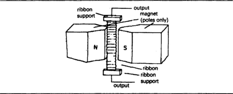
Figure 8.4 The ribbon microphone, the form of construction that provides the highest-quality of conversion from sound to electrical waves.
The piezoelectric microphone uses a piezoelectric crystal element either alone or (not so commonly nowadays) connected to a diaphragm. The crystal, a material such as barium titanate, is one in which the arrangement of atoms ensures that any tiny displacement of the atoms due to vibration will cause a voltage to be generated across the crystal, and this is sensed by depositing conducting films across opposite faces of the crystal, to which the output leads are connected. The impedance level is of the order of several megohms, as distinct to a few ohms for a moving-coil type, and the output is in the high millivolt range rather than microvolts.
The capacitor microphone is a remarkable example of a principle that was comparatively neglected until another equally old idea was harnessed along with it. The outline of a capacitor microphone is illustrated in Figure 8.5. The amount of electrical charge between two surfaces is fixed and one of the surfaces is a diaphragm which can be vibrated by a sound wave. The vibration causes a variation of capacitance which, because of the fixed charge, causes in turn a voltage wave. The output impedance is very high, and the amount of output depends on the normal spacing between the plates – the smaller this spacing, the greater the output for a given amplitude of sound wave, and the poorer the linearity.
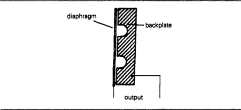
Figure 8.5 Capacitor microphone principle in its original form. This type of microphone has enjoyed a revival thanks to the use of electret materials.
A high-voltage supply (the polarizing voltage) is needed to provide the equivalent of a fixed charge by being connected across the plates through a resistor of very large value, and this polarizing requirement at one time deterred the widespread use of the capacitor microphone despite its good performance. The revival of the capacitor microphone came about as a result of improving the technology of an old idea, the electret.
An electret is the electrostatic equivalent of a magnet, a piece of insulating material which is permanently charged. A slab of electret is therefore the perfect basis for a capacitor microphone, providing the fixed charge that is required without the need for a polarizing voltage supply. This allows very simple construction of a capacitor microphone, consisting only of a slab of electret metallized on the back, a metal (or metallized plastic) diaphragm, and a spacer ring (Figure 8.6), with the connections taken to the conducting surface of the diaphragm and of the electret. This is now the type of microphone which is built into cassette recorders, and even in its simplest and cheapest versions is of considerably better audio quality than the piezoelectric types that it displaced. The use of a FET preamp solves the problem of the high impedance of this type of microphone.
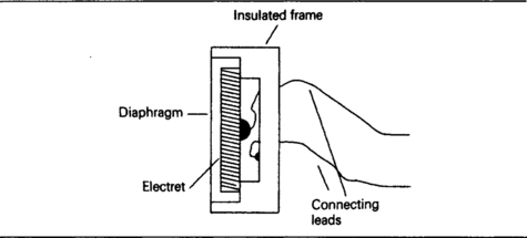
Figure 8.6 The electret microphone in cross-section. There is no need for a polarizing voltage, but the impedance of the microphone is very high, and a FET preamp must be used.
Electrets currently in use consist of plastics materials such as Perspex which are subjected to an intense electric field while they are solidifying. There is no source of ready-made electrets, because the usual requirement for electrets calls for a custom shape of plastic, and it’s more convenient for the end-user to form the plastic and polarize it.
Loudspeakers and earphones
Earphones have been in use for considerably longer than microphones or loudspeakers, since they were originally used for electric telegraphs. There is an earphone and loudspeaker form of construction to match each type of microphone listed above, because these transducer types are all reversible (something quite rare among transducers). The task of the earphone is somewhat simpler than that of the loudspeaker, and the construction of an earphone that can provide acceptable quality of sound is very much simpler (and correspondingly cheaper) than that of a loudspeaker, since the earphone can use a small diaphragm, and ensure that the sound waves from this diaphragm are coupled directly to the ear cavity. The power that is required is in the low milliwatt level, and even a few milliwatts can produce considerable pressure amplitude at the eardrum – often more than is safe for the hearing.
A loudspeaker, by contrast, has its sound waves launched into a space whose properties are unknown, and it has to be housed in a cabinet whose resonances, dimensions and shape will considerably modify the performance of the loudspeaker unit. The assembly of loudspeaker and cabinet will be placed in a room whose dimensions and furnishing are outside the control of the loudspeaker designer, so that a whole new set of resonances and the presence of damping material must be considered. The transducer of a loudspeaker system is sometimes termed the ‘pressure unit’, and its task is to transform an electrical wave, which can be of a very complex shape, into an air-pressure wave of the same waveform. To do this, the device requires a motor unit, transforming electrical waves into vibration, and a diaphragm which will move sufficient air to make the effect audible. The diaphragm is one of the main problems of loudspeaker design, because it must be very stiff, curved, very light and free of resonances, an impossible combination of virtues. Practically every material known has been used for loudspeaker diaphragms at some time, from the classic varnished paper to titanium alloy and carbon fibre, and almost every shape variation on the traditional cone has been used.
The efficiency of loudspeakers is notoriously low, around 1%, mainly because of the acoustic impedance matching problem. In simple terms, most loudspeakers move a small amount of air with a comparatively large amplitude, whereas to produce a sound wave effectively they ought to move a very large amount of air at a comparatively low amplitude. This mismatch can be remedied to some extent by housing the loudspeaker in a suitable enclosure.
The efficiency is lowest at low frequencies, typically 20 Hz, and a loudspeaker will be designed so that the efficiency does not rise greatly above the low-frequency level. This greatly helps in achieving a reasonably level frequency response. A loudspeaker designed specifically for a small range of (higher) frequencies can be much more efficient, typically 10% or more, and some piezoelectric warning devices, as fitted to smoke alarms, can achieve almost 25% efficiency.
The first type of successful earphone transducer was a moving-iron type, and this principle was used extensively for both earphones and for loudspeakers earlier in the twentieth century. Moving-iron units are seldom encountered now except in telephone earpieces. The conventional telephone earphone uses a magnetized metal diaphragm so that the variation of magnetization of the fixed coil will ensure the correct movement of the diaphragm. The unit is sensitive but the linearity is poor and moving-iron units are seldom used.
The moving-coil principle as applied to loudspeakers and earphones has, by contrast, been widely adopted, and the vast majority of loudspeakers use this principle. The use of moving-coil earphones has been less common in the past, but these are now in widespread use thanks to the miniature cassette player vogue. As applied to earphones, moving-coil construction permits good linearity and controllable resonances, since the amount of vibration is very small and the moving-coil unit is light and can use a diaphragm of almost any suitable material. A variation of the moving-coil principle that has been successfully used for earphones is the electrodynamic (or orthodynamic) principle. This uses a diaphragm which has a coil built in, using printed circuit board techniques. The coil can be a simple spiral design, or a more complicated shape (for better linearity), and the advantage of the method is that the driving force is more evenly distributed over the surface of the diaphragm. Headphones based on this principle have been very successful and of excellent quality.
The ribbon principle is also used to provide loudspeaker action. The moving element of a ribbon loudspeaker is necessarily small, and for that reason the unit is more often confined to high-frequency use (a tweeter) rather than for full-range reproduction. Wide-range multi-ribbon units are also feasible, but in a very different size (and price) category. The commercially available types use three units, of which the bass unit is very large, and which requires its own amplifier to supply about 100–1000 W driving power. The highest power levels are used by sub-woofers, with a restricted frequency range around 20–50 Hz.
The piezoelectric principle has also been used for earphones in the form of piezoelectric (more correctly, pyroelectric, since the electrical parameters are temperature sensitive) plastics sheets which can be formed into very flexible diaphragms. The moving mass is very small and sensitivity is high with no need for a power supply, so that the device is passive. The linearity is not particularly good.
The Quad wide-range electrostatic loudspeaker is one of the very few examples of full-range loudspeakers using the electrostatic principle, although the system has also been used in earphones which, despite the need to provide a high polarizing voltage for the plates, have been very popular and of outstanding audio quality. The advantage that makes the electrostatic loudspeaker principle so attractive is that the driving effort is not applied at a point in the centre of a cone or diaphragm, but to the whole of a surface that can be large in area, satisfying the requirement of moving a large area of air. Electrostatic earphones using electrets permit high-quality listening without the need for a high voltage to be supplied.
Ultrasonic waves
Some transducers that are used for sending or receiving ultrasonic signals through solids or liquids can operate in either direction if required, but for ultrasonic signals sent through the air (or other gases), the transducers are used with diaphragms and in enclosures that can make the application more specialized so that a transmitter or a receiver unit has to be used for its specific purpose. The important ultrasonic transducers are all piezoelectric or magnetostrictive, because these types of transducers make use of vibration in the bulk of the material, as distinct from vibrating a motor unit which then has to be coupled to another material.
Magnetostriction is the change of dimensions of a magnetic material as it is magnetized and demagnetized. Several types of nickel alloys are strongly magnetostrictive, and have been used in transducers for the lower ultrasonic frequencies, in the range 3–100 kHz. A magnetostrictive transducer consists of a magnetostrictive metal core on which is wound a coil. The electrical waveform is applied to the coil, whose inductance is usually fairly high, so restricting the use of the system to the lower ultrasonic frequencies. For a large-enough driving current, the core magnetostriction will cause vibration, and this will be considerably intensified if the size of the core and the operating frequency are matched so as to achieve mechanical resonance. The main use of magnetostrictive transducers has been in ultrasonic cleaning baths, as used by watchmakers and in the electronics industry.
The piezoelectric transducers have a much larger range of application, although the maximum possible power output cannot approach that of a magnetostrictive unit (which can be constructed to any size; there is a limit to the practical size of a crystal and to its internal dissipation). The transducer crystals are barium titanate or quartz, and these are cut so as to produce the maximum vibration output or sensitivity in a given direction. The crystals are metallized on opposite faces to provide the electrical contacts, and can then be used either as transmitters or as receivers of ultrasonic waves. The impedance levels are high, and the signal levels will be millivolts when used as a receiver, a few volts when used as a transmitter.
Magnetic transducers
Changes in magnetic fields can be detected using a coil, because a voltage will be induced in a coil when the magnetic flux through the coil changes. Modern methods of measuring magnetic fields, however, all rely on the Hall effect. The Hall effect is an example of the action of a magnetic effect on moving charged particles, such as electrons or holes, and it was the way in which hole movement in metals and semiconductors was first proved. The principle is a comparatively simple one, but for most materials detecting the effect requires very precise measurements.
The principle is illustrated in Figure 8.7. If we imagine a slab of material carrying current from left to right, this current, if carried entirely by electrons would consist of a flow of electrons from right to left. Now for a current and a field in the directions shown, the force on the conductor will be upwards, and this force is exerted on the particles that carry the current, the electrons. There should therefore be more electrons on the top surface than on the bottom surface, causing a voltage difference, the Hall voltage, between the top and bottom of the slab. Since the electrons are negatively charged, the top of the slab is negative and the bottom positive. If the main carriers are holes, the voltage direction is reversed.
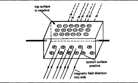
Figure 8.7 The Hall effect. The size of the voltage that is produced by the effect of a magnetic field is large only when semiconductor materials are used.
The Hall voltage is very small in good conductors, because the particles move so rapidly that there is not enough time to deflect a substantial number in this way unless a very large magnetic field is used. In semiconductor materials, however, the particles move slowly, and the Hall voltages can be comparatively substantial, enough to produce a measurable voltage of a few μV for only small magnetic fields such as the horizontal component of the earth’s field. Small slabs of semiconductor are used for the measurement of magnetic fields in Hall-effect fluxmeters and in electronic compasses. A constant current is passed through the slab, and the voltage between the faces is set to zero in the absence of a magnetic field. With a field present, the voltage is proportional to the size of the field.
Photocells
A photocell is a light-to-electrical transducer, and there are many different types available. Light is an electromagnetic radiation of the same kind as radio waves, but with a very much shorter wavelength and hence a much higher frequency. Light radiation carries energy, and the amount of energy carried depends on the square of the amplitude of the wave. In addition, the unit energy depends on the frequency of the wave. The sensitivity of photocells can be quoted in either of two ways, either as the electrical output at a given illumination, using illumination figures in units of lux, often 50 lux and 1000 lux, or as a figure of power falling on the cell per square centimetre of sensitive area, a quantity known as irradiance. The lux figures for illumination are those obtained by using photometers, and a figure of 50 lux corresponds to a ‘normal’ domestic lighting level good enough for reading a newspaper. A value of 1000 lux is the level of illumination required for close inspection work and the reading of fine print; on this scale, direct sunlight registers at about 100 000 lux. The use of milliwatts per square centimetre looks more comprehensible to anyone brought up with electronics, but there is no simple direct conversion between power per square centimetre and lux unless other quantities such as spectral composition (colour balance) of light are maintained constant. For the range of wavelengths used in photocells, however, you will often see the approximate figure of 1 mW/cm2 = 200 lux used.
Another important point relating to the use of photocells is that they are not uniformly sensitive at all visible colours. For many types of sensors, the peak sensitivity may be at either the red or the violet end of the visible spectrum, and some sensors will have their peak response for invisible radiation either in the infrared or the ultraviolet. A few devices, notably some silicon photodiodes, have their peak sensitivity for the same colour as the peak sensitivity of the human eye. The main classes of photocells are photoresistors, photovoltaic materials, and photoemitters.
Photocell types
The photoemissive cell was the dominant type of photosensor for many years. This is a vacuum device, and since it requires a power supply for operation is not strictly a passive device. In addition, the use of photoemissive cells is now rather specialized. The photoresistor also needs a DC supply, and consists of a material which has high resistance in the absence of light, and a much lower resistance when the material is illuminated.
The effect of light on a photodiode is to generate electron-hole pairs in a reverse-biased junction, and the result is that current can flow when light strikes the junction, equivalent to a decrease in the reverse resistance.
PHOTORESISTORS
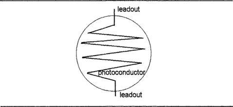
The most common form of photoresistive cell is the cadmium sulphide cell, named after the material used as a photoconductor. This is often referred to as an LDR (light-dependent resistor). The cadmium sulphide is deposited as a thread pattern on an insulator, and since the length of this pattern affects the sensitivity, the shape is usually a zigzag line (Figure 8.8). The cell is then encapsulated in a transparent resin or encased in glass to protect the cadmium sulphide from contamination from the atmosphere. The cell is very rugged and can withstand a considerable range of temperatures, either in storage or during operation. The voltage range can also be considerable, particularly when a long track length of cadmium sulphide has been used, and this type of cell is one of the few devices that can be used with an AC supply. One less-welcome feature is that there is a considerable time lag (of the order of several hundred milliseconds) on turning off (increasing resistance when the light is extinguished or dimmed). The switch-on time is less, typically one-fifth of the turn-off time.
PHOTODIODE AND PHOTOTRANSISTOR
A photodiode can be regarded as a high-impedance non-ohmic photosensitive device whose current is almost independent of applied voltage. The incident light falls on a reverse-biased semiconductor junction, and the separation of electrons from holes will allow the junction to conduct despite the reverse bias. Photodiodes are constructed like any other diodes, using silicon, but without the opaque coating that is normally used on signal and rectifier diodes. The junction area may be quite large, so that photodiode may have more capacitance between electrodes than a conventional signal diode. This can be compensated by using a feedback capacitor in the circuit, illustrated in Figure 8.9, which shows a typical circuit for using a photodiode along with an operational amplifier for a voltage output. The feedback resistor R will determine the output voltage, which will be RI, where I is the diode current.
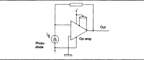
Figure 8.9 The output of the photodiode is normally very small, and amplification is almost always needed.
A phototransistor is a form of transistor in which the base-collector junction is not covered and can be affected by incident light – it is virtually a photodiode with a base-emitter junction added. The base-collector junction acts as a photodiode, and the current in this junction is then amplified by the normal transistor action so as to provide a much larger collector current, typically one thousand times greater than the output current of a photodiode. The bandwidth is, however, lower. A considerable range of current gain and bandwidth can be obtained. The phototransistor is therefore not a passive component and will not be considered further here.
PHOTOVOLTAIC CELLS
Photovoltaic devices are the only truly passive type of photocells. The first form of photovoltaic device was the selenium cell as used in early types of photographic exposure meters. The principle is that the voltage across the cell depends logarithmically on the illumination, and since for the selenium cell the voltage was of an appreciable size (of the order of 1 V or more in bright illumination) an exposure meter using this type of cell needed no amplification, and could use a meter of reasonably rugged construction. Modern photovoltaic devices are constructed from silicon, and the construction method is as for a photodiode. A silicon photovoltaic device is a silicon photodiode with a large area junction and used without bias. It is connected into a large load resistance, and the typical voltage output is of the order of 0.5 V for bright artificial illumination of 1000 lux.
A more recent application for silicon photovoltaic cells is in electricity generation, using cells in series with a typical output of 0.25 V each, generating enough current to be used to recharge batteries. Series–parallel units can be used to supply DV at a higher level that can be inverted into AC 220 V in areas where no other source of supply is possible. This system can be used for powering remote sensors such as weather stations, and is widely used in satellite power supplies (where the sunlight can be intense and constant).
Electrical to light transducers
LEDs are diodes in which conduction causes the emission of light in the visible range. The majority of LEDs in use are of gallium phosphide or gallium arsenide phosphide construction and are electrically diodes with a high forward voltage of about 2 V, depending on type, and a very small peak reverse voltage of about 3 V. In use, then, great care is needed to ensure correct polarity of connection so as to avoid burning out the LED. Limiting resistors are usually wired in series to prevent burn-out due to excessive current.
The intensity of illumination from the LED depends fairly linearly on the forward current, and this can range from 2 to 30 mA, depending on the physical size of the unit and the brightness required. A few types can operate at 100 mA. The colour of the LED is determined by the material, and the two predominant colours are red and green, although blue can now be obtained. The use of red and green sources close to each other can be used to give yellow light, in accordance with the rules on mixing of light colours, so that the colours red, green, yellow and white can easily be obtained from a single LED package. The use of twin diodes in a package can allow switchable red, green and yellow lights to be obtained, and when LEDs are supplied as part of a package with IC digital units, flashing LED action can be obtained.
Single LEDs are obtainable in a considerable variety of physical forms, of which the standard dot and bar types predominate. The bar type of LED, using semiconductor material in bar form rather than a set of dots, can usually be obtained in intensity matched form, in which the intensity at a specified current rating is matched closely enough to allow the units to be stacked to be used as a column display. In a display of this type, a diode whose intensity is higher or lower than the others is particularly obvious, hence the need for intensity matching.
Opto-couplers and opto-isolators make use of an LED and a phototransistor in one package so that the light output of the LED is the light input for the phototransistor. Since the signal coupling is by way of a light path, which can be of whatever length the design requires, there can be a very high degree of isolation between electrical input and electrical output. The opto-isolator is a more critical component, using the isolation for electrical safety purposes; the opto-coupler, used to pass signals between very widely differing DC levels, requires less isolation.
Thermocouples
A thermocouple is a temperature (or, more correctly, a temperature difference) transducer with an electrical output. The principle is that two dissimilar metals always have a contact potential between them, and this contact potential changes as the temperature changes. The contact potential is not measurable for a single connection (or junction), but when two junctions are in a circuit (Figure 8.10) with the junctions at different temperatures then a voltage of a few microvolts per degree can be detected. This voltage will be zero if the junctions are at the same temperature, and a plot of voltage against temperature difference is approximately linear.
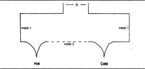
Figure 8.10 A thermocouple junction exists where two differing metals meet, and when two junctions exist in a circuit this produces a voltage of a few millivolts when there is a temperature difference between the two junctions.
• There are always several junctions in a circuit, because a junction exists wherever two different conducting materials meet, and if copper wire is used for the circuit there will be a junction where one of the thermocouple metals joins to the copper. The essence of a thermocouple, however, is that these other junctions are all at a constant temperature and make no net contribution to the output voltage.
Some combinations of metals will give a parabolic characteristic, and are therefore not used for thermocouples. Most materials will provide a linear 0°C to 100°C range and combinations such as platinum–rhodium provide much larger linear ranges. The output from a thermocouple is small, at most a few millivolts for a 100°C temperature difference, and more typically a fraction of a millivolt. If the output of the thermocouple is required to drive anything more than a meter movement, then DC amplification will be needed, using an operational amplifier or chopper amplifier.
RESISTANCE THERMOMETERS
Resistance thermometer transducers, also known as RTDs (resistance temperature detectors) depend on the change of resistivity of any material when the temperature changes, and this change in the resistivity causes a change of resistance. The resistance change is not linear, particularly over a large range of temperatures, but the linearity can be improved by using an active circuit with a small amount of positive feedback. Resistance thermometers are often used in applications that call for the measurement of very high temperatures.
For comparatively small temperature ranges, up to 400°C or so, the resistance change of nickel or of nickel alloys can be used, and for higher temperature ranges, platinum and its alloys are more suitable because of their much greater resistance to oxidation. For measurement purposes, the resistance sensor can be connected to a measuring bridge, along with a dummy sensor whose temperature is kept constant. The platinum-resistance thermometer is a standard type, calibrated from the ultimate but inconvenient temperature reference of a gas expansion thermometer. Platinum sensors can now be obtained in thin-film or thick-film forms of various shapes and sizes, at much lower cost than the older platinum-wire types.
Thermistors
Thermistors are a form of temperature-sensitive resistor formed using mixtures of oxides of exotic metals. The constructional methods are similar to those used for carbon composition resistors. Some of these mixtures have positive temperature coefficients, and in most cases it would be meaningless to quote a value for temperature coefficient, positive or negative, because the value is not a constant. The thermistors with a positive temperature coefficient are very non-linear, but the more common negative temperature coefficient types follow a roughly logarithmic law with no violent changes in resistance.
Given that the resistance of a thermistor is known at one temperature θ2, it can be calculated for another temperature θ1 by using the formula which is illustrated in Table 8.1. The use of θ rather than T for temperature in this formula is a reminder that the temperatures must be in units of Kelvins (absolute temperatures). The Kelvin or absolute temperature is obtained by adding 273 to the Celsius temperature. If you need to work to two places of decimals of temperature, use the figure 273.16.
Table 8.1
Thermistor formulae that relate resistance to temperature
The temperature coefficient of a thermistor Is not a constant, but Itself varies as temperature changes. A more useful quantity Is the thermistor constant B which can be used to find the resistance at any temperature In the worlcing range provided another pair of resistance and temperature values are known.
![]()
θ and B values are In Kelvin (K) units of temperature.
For example, If the thermistor constant B Is known to be 3200 K, and the resistance at 30°C Is 2 k, then the resistance at 45°C can be calculated as follows:
The temperatures are 293 K and 318 K, so that the quantity in brackets Is 0.8586. Using the EXP function of a calculator, R2 = 2×2.359 = 4.719 about 4k7.
Thermistors can be obtained in a variety of physical forms, as beads, miniature beads, plates, rods, and also encapsulated in metal containers.
NTC thermistors are used for temperature control applications such as low-temperature oven controllers, deep-freezer thermostats, room temperature sensors and process controllers. Temperature limits range from 150°C to 200°C, with a few types able to withstand 600°C. The range of temperature that a thermistor can handle depends on the associated circuit, because the range of resistance will be very large compared to the range of temperature.
In any of these applications, NTC thermistors have considerable advantages as compared to the old bimetal thermostat, notably the absence of any hysteresis effects (switching on at a different temperature than that for switching off). NTC thermistors can also be obtained in evacuated envelopes for use in such purposes as oscillator limiters and controllers for voltage-controlled amplifiers.
Thermistor circuits in general require the use of preset potentiometers in order to make working adjustments, but circuit costs can be reduced by employing curve matched thermistors whose resistance values are guaranteed to within close limits at each of a large range of temperatures. Thermistors of all types will also have quoted values of dissipation constant and time constant. The dissipation constant is the amount of power (in milliwatts) that is required to raise the temperature of the thermistor by 1°C above the ambient temperature. For the evacuated bulb type, the dissipation constant is very small, of the order of 12 μW/°C, so that the resistance of this type of thermistor is substantially altered by only very small amounts of signal current. For temperature-sensing thermistors, values of dissipation constant in the range 70–500 μW/°C are typical.
The time constant for a thermistor is defined as the time needed for the resistance to alter by 63% of the difference between an initial value and a final value caused by a change of temperature. Time constant is measured with negligible current flowing, because otherwise the figure would be altered because of part of the heating being internal rather than external. The figure of 63%) may seem odd, but it corresponds to the definition of time constant for other networks such as a capacitor and a resistor, and by making the definition in this way, the value of time constant is genuinely constant over a large range of temperature changes. Time constants of 5–11 seconds are typical of the physically small thermistors (miniature beads and the evacuated bulb types), with much larger values for others, 18–25 seconds for the larger beads, and as high as 180 seconds for thermistors that have been assembled into temperature-sensing probes.
Negative temperature coefficient (NTC) thermistors can be constructed from semiconducting materials with values of temperature coefficients that are usually much larger than the (positive) temperature coefficients of resistors. The phrase NTC resistor is used for devices with fairly small negative values of temperature coefficient, and the term thermistor is reserved for the types that have large negative values of temperature coefficient. Most of the thermistors that are incorporated into temperature-sensing circuits are of the NTC type.
PTC THERMISTORS
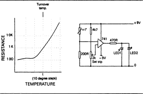
Positive temperature coefficient (PTC) thermistors are a more recent development, used mainly for protection circuits for sensing temperature or current. Unlike the NTC types, these PTC thermistors have a current–voltage characteristic that exhibits a change in direction, and two basic types are used, both depending on compounds of barium, lead and strontium titanates (ceramic materials). The overtemperature protection type of PTC device has a switch-over point at a reference temperature (or trip temperature, Tr). At temperatures lower than the trip temperature the resistance of the PTC device is fairly constant, but around the trip temperature the PTC characteristic takes over and their resistance rises very sharply as the temperature rises. A typical graph of resistance plotted against temperature, along with a trip-sensing circuit, is shown in Figure 8.11. The sudden change in resistance can be used to operate an indicator or to switch other circuits for purposes such as motor protection or for preventing overheating of transformers.
The other type of PTC thermistor device is used for overcurrent protection circuits, and its resistance/temperature graph is illustrated in Figure 8.12. This characteristic follows an S-shaped curve which has two turn-over points, one at a point of minimum resistance Rmin and the other at the maximum resistance point Rmax. Between 0°C and Rmin, the temperature coefficient is negative, and the coefficient is also negative at the temperatures in the region higher than Rmax. Between Rmin and Rmax the temperature coefficient is large and positive. In this PTC region, the change of resistance can be as large as 100% for each degree Celsius rise in temperature.
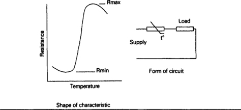
Figure 8.12 The type of characteristic used for current protection devices operated by a PTC thermistor.
With one of these devices wired in series with a load, the load is protected against excessive current. At the working current, the PTC device is in its low-resistance state, allowing most of the applied voltage to be across the load. When the current is increased, the thermistor will suddenly switch to its PTC mode, assisted by self-heating as more of the applied voltage will now be across the thermistor, until the current flowing in the whole circuit becomes very small. The circuit can be arranged so that it is self-resetting, returning to normal when the thermistor cools, or requires the circuit to be reset by switching off the current and allowing the thermistor to cool.
Mechanical quantities
A resistive strain gauge consists of a conducting material in the form of a thin wire or strip which is attached firmly to the material in which strain is to be detected. This material might be the wall of a building, a turbine blade, part of a bridge, anything in which excessive stress could signal impending trouble. The fastening of the resistive material is usually by means of epoxy resins such as Araldite, but ceramic pastes are used for high-temperature applications. Electrically, the strain gauge strip is connected as part of a resistance bridge circuit (Figure 8.13). The effects of temperature can be minimized by using another identical unstrained strain gauge in the bridge as a comparison.

Figure 8.13 The strain gauge principle. The strain gauge element can be made from a metal strip, but silicon is much more common because of its much higher sensitivity.
The use of a semiconductor strip in place of a metal wire makes measurement much easier, because the resistance of such a strip can be considerably greater, and so the changes in resistance can be correspondingly greater. Except for applications in which the temperature of the element is high (gas-turbine blades, for example), the semiconductor type of strain gauge is preferred.
Piezoelectric strain gauges are useful where the strain is of short duration, or rapidly changing in value. The voltage can be very large, of the order of several kilovolts for a heavily-strained crystal, so that the gauge can be sensitive, but the output impedance is very high and capacitive. The output is not DC, therefore, so that this type of gauge is not useful for detecting slow changes, and its main application is for acceleration sensing.
Surface acoustic wave devices
Quartz crystals, cut into thin plates and with electrodes plated on to opposite flat faces, can be used as resonant circuits with Q values ranging from 20 000 to 1 000 000 or more. The equivalent circuit of a crystal is shown in Figure 8.14. The crystal by itself acts as a series resonant circuit with a very large inductance, small capacitance and fairly low resistance (a few thousand ohms). The stray capacitance across the crystal will also permit parallel resonance to occur at a frequency that is slightly higher than that of the series resonance. Figure 8.15 shows how the reactance and the resistance of a crystal vary as the frequency is changed – the reactance is zero at each resonant frequency and the resistance is maximum at the parallel resonant frequency. Usually the parallel and the series resonant frequencies are specified when the crystal is manufactured. In these applications, the quartz crystal is acting as an electrical-to-acoustic transducer, and a development of this principle uses transducer crystals that have a reversible action, so that the acoustic-to-electrical conversion is used also.


Figure 8.15 Variation of reactance and resistance of a quartz crystal near its resonant frequencies.
A surface acoustic wave (SAW) device is an arrangement that uses two transducers back to back with electrical input and electrical output but with an acoustic wave (which is usually ultrasonic) between. A signal input to one transducer causes the wave to be set up, and the wave reaching the second transducer causes an electrical output at the same frequency, but delayed compared to the original signal. The device can be used purely as a signal delay, and the best-known example is the delay line originally used for decoding the PAL colour TV signal. This is made from glass cast into a V shape (Figure 8.16), with one transducer converting the video signal into an ultrasonic wave which reflects and hits the other transducer some time later. The precise time can be adjusted by trimming the reflecting end of the glass.
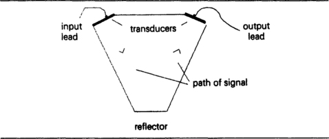
Figure 8.16 The form of a glass delay line as used for early PAL colour TV receivers. The delay can be adjusted by grinding the apex.
Delay lines of this type can give delays of milliseconds as compared to the microseconds that can be achieved with electrical lines or with GC networks. The output signal is very considerably attenuated as compared to the input signal, so that amplification is needed both before and following the delay line. This type of analogue delay device has now been superseded by digital delays which can be adjusted more easily.
The other main SAW application is filtering. These are used wherever a steep cut-off form of filter is needed without the problems of ringing that would appear if a conventional LC filter were used; that is, if a conventional LC filter could be designed to achieve such steep cut-off. Typical applications are in the PAL TV system to separate subcarriers, and in CD players to avoid ‘aliasing’ due to harmonics.
If the transducers are formed on a crystal which has a mechanical resonance, the output will be strongly frequency dependent, and the equivalent Q of the arrangement can be very high, almost in the quartz crystal regions of 30 000 or so. An added advantage is that by careful mechanical design, band-pass filters can be constructed which have a very steep transition between pass-band and stop-band, very much better than can ever be achieved with any LC combination, active or passive.