
Inductors and inductive components
Induction and inductance
Electromagnetic induction was discovered by Michael Faraday in 1831. The principle is that an EMF (a voltage) is generated in a conductor when the magnetic field across the conductor changes. In the early experiments, the change of magnetic field was accomplished by moving either the wire or a magnet, and this is the principle of the alternator and dynamo. An EMF can also be induced without mechanical movement, when the strength or direction of a magnetic field across a wire is altered, and even the presence of a wire is not necessary, because the alteration in a magnetic field can produce an electric field in the absence of any conductor. Inductive components in electronics make use of the EMF that is generated when a field changes either in the same piece of wire (self-induction) or in another piece of wire (mutual induction).
The amount of EMF that is generated in a wire can be greatly increased if the wire is wound into a coil, and as much as possible of the magnetic field is guided through the coil. Figure 5.1 shows the flux path in a solenoidal winding for a steady current. Concentration and guidance of the magnetic field is achieved by using a magnetic core, for which the traditional material was annealed ‘soft’ iron. One way of looking at a soft iron core is as a conductor for magnetism, using the idea of magnetic flux. It is possible to think of magnetic circuits in which magnetic flux (φ) is the counterpart of current, in a path which has reluctance (analogous to resistance), and in which the amount of flux is produced by a magnetomotive force (MMF). The equation that is the magnetic equivalent of V = R × I is then:

with φ representing the amount of flux and S the reluctance of the magnetic circuit.
This allows magnetic circuits to be analysed much in the same way as we analyse current circuits, so that if a transformer uses a large iron core with a small air gap then values for reluctance for both the core and the air gap can be calculated, and these will add, as the values of resistors in series are added. The total MMF can be calculated from knowing the number of turns of magnetizing winding and the current flowing, so that the amount of flux can be calculated. For any such arrangement, the air gap is the determining factor, acting like a large resistance in a current circuit, which makes the variable values of other resistances in series virtually negligible in effect. The simplest inductive component, other than a straight wire, is a coil of wire with no metal core. A changing current in this coil produces a changing magnetic field, and this in turn induces an EMF in the coil itself. By Lenz’s law, this EMF is in a direction that always opposes the change that causes it. Therefore if the changing magnetic field is caused by an increase of current when a voltage is applied, the induced EMF will be in the opposite direction, reducing the current.
If the changing magnetic field is decreasing because the current has been interrupted, the induced EMF will be in a direction that will increase the voltage at the interruption in the circuit, causing a spark so as to continue the current. Because the EMF is always in a direction that opposes any change of current it is usually referred to as the back-EMF. This simple single-coil arrangement has self-inductance, and is a single inductor.
The practical definition of self-inductance is illustrated in Figure 5.2, as the constant L in the equation. When the back-EMF is measured in volts, with rate of change of current in units of amperes per second, then the unit of self-inductance is the henry (H).

Figure 5.2 Self-inductance, L, defined in terms of the voltage generated by a sudden change of current.
Large inductors can be obtained with values of several henries, but for many purposes the smaller units of millihenry (mH) and microhenry (μH) are used. For a coil with only air in its core, or any non-metallic material, and with a length that is large compared to its radius, the value of self-inductance L can be calculated from the dimensions of the coil and its number of turns (Figure 5.3). This value of L is a constant.

Figure 5.3 Approximate inductance for an air-cored single-layer coil (a solenoid), with L in μH, s and r in centimetres.
When a core of magnetic material is used, the value of L is enormously increased. The increase is very much greater than the effect of a solid dielectric on the capacitance of parallel plates, and is due to the relative permeability of the magnetic material (compare the effect of relative permittivity for a dielectric). The effects are not comparable, however, because whereas relative permittivity of a dielectric is a constant, the relative permeability of a magnetic material is variable – it depends on the value of magnetic field around the materials, and the permeability values that existed previously (the magnetic history). The uncertainty of the value of relative permeability makes working with inductors considerably more difficult than working with capacitors or resistors, and for many years the use of inductors in circuits has been declining. The use of ICs has hastened this trend, and devices such as surface-wave filters (see Chapter 8) which make use of acoustic waves have superseded the use of inductors in many types of tuned circuits.
As well as self-induction, we can have mutual induction, in which the rate of change of current in one coil causes an induced back-EMF in another coil. The definition of a coefficient of mutual inductance, M, is shown in Figure 5.5, and since the units of EMF, current and time are the same, the unit of M is also the henry. Mutual inductance is the mechanism of transformers, which are generally bought ready-made, although RF transformers, consisting of two windings on a non-metallic core, are often assembled for one-off applications.

Figure 5.5 Definition of coefficient of mutual inductance, M. Mutual inductance is very difficult to estimate and ‘cut and-try’ methods often have to be used.
Despite the trend to dispense with inductors there is still a substantial need for inductors of all kinds, particularly for development work. Unlike capacitors and resistors, inductors other than power transformers are seldom available in the UK as stock items, and most have to be wound as needed on cores whose contribution can be quantified by the manufacturer. Some components catalogues in the UK make little reference to inductors for other than mains or audio uses, but supplies are readily available from the US and other sources. In some ways, inductors are the last lingering reminder that we have of the early days of radio when the experimenter had to make each and every passive component.

Core materials and permeability
The fact that electromagnetic waves can travel through empty space implies that space has a value of permittivity and also of permeability. The value of the permeability of free space, ![]() 0, is, in absolute units, approximately 1.26 × 10⁻⁶ henries per metre (compare the absolute units of permittivity, which are farads per metre), so that no material will have a permeability value of less than this. The relative permeability of a material,
0, is, in absolute units, approximately 1.26 × 10⁻⁶ henries per metre (compare the absolute units of permittivity, which are farads per metre), so that no material will have a permeability value of less than this. The relative permeability of a material, ![]() r, is defined by:
r, is defined by:
so that relative permeability is a pure number, a factor that is the ratio of the permeability of a material to the permeability of free space. Relative permeability values of as high as 106 are possible in practical conditions. In theory, the relative permeability of any magnetic material can take any value from almost unity to ∞00. In practice, we can usually find a working average value for a magnetic core material that can be used to calculate the likely self-or mutual inductance of a coil or coils respectively.
The difficulty of using permeability values is illustrated by Figure 5.6, which is a typical magnetizing–demagnetizing graph for a magnetic material. On this type of graph, the magnetic flux density (field strength) is displayed vertically, and the magnetizing current is plotted horizontally. If the material is initially unmagnetized, then the graph starts from the centre and reaches a maximum. This maximum expresses the saturation field strength – the core material is fully magnetized and increasing the amount of current through the coil will make only a very small change to the magnetism. When the current in the coil is reduced from this saturation value, the graph follows a hysteresis shape, meaning that the path that is followed for reducing current is not the same as the path for increasing current. There will be a magnetic flux density when no current flows through the coil. This is the residual magnetism or remanence of the core, and for the type of cores that are used for inductors in electronics, this residual magnetism should be very small, almost negligible.
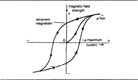
Figure 5.6 A graph of magnetic flux density plotted against magnetizing current. The permeability is represented by the slope of this line, which varies between almost zero and a very large value. Permeability, unlike permittivity, is not a constant.
• One exception in the past (around 1950–1960) was the use of core memory for computers in the dinosaur era, which used small magnetic cores with several windings (usually single turn) as a form of memory, with one direction of magnetization signifying a 0 bit, and the opposite direction a 1 bit.
When the current in the coil is reversed, there will be a point when the reverse current has reduced the new magnetic flux to zero, and when the current is increased further in this negative direction, the flux density will rise to a saturation level in this direction. Returning the current to zero and then to a positive value will then trace the remainder of the curve, but the initial section will not be retraced unless the material is totally demagnetized (usually by heat treatment).
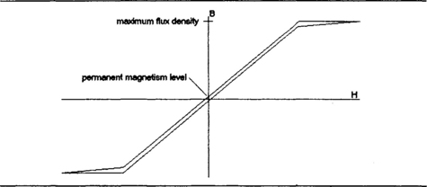
The types of materials that are used as cores for inductors for many types of electronics applications have hysteresis curves that are typified by Figure 5.7, in which the residual magnetism is almost negligible. Such a material is called a ‘soft’ magnetic material, so called because the first such material to be discovered was soft (annealed) iron. Because the shape of the hysteresis curve around the central portion is almost straight, an average value of permeability can be measured for this region and used in calculations. Since this value must always be approximate, and because there is often a quite substantial temperature coefficient of inductance (in the range 100–200 ppm/°C), these self-inductors are often adjustable. Very few suppliers quote the temperature coefficient of inductance for their products. The adjustability is by movement of the core which is threaded and screwed into a plastic former so as to allow the self-inductance value to be adjusted, usually by +20%. The portion of hysteresis curve that is used depends on the amount of any DC that flows in the inductor, so the value of inductance will depend heavily on the amount of such DC, and many inductors are designed for signal use only, or for use with very small amounts of DC only. The effect of large direct currents in an inductor concerns mainly the larger iron-cored inductors, mainly mains transformers, and will be considered later.
Inductive reactance
A self-inductor generates a back-EMF whose size depends on the rate of change of current, so a self-inductor with an applied AC voltage will have an AC back-EMF, which will be out of phase with the applied voltage. The result is that an inductor will pass much less alternating current than its DC resistance would imply, and the current will be in a phase which is 90° lagging behind the applied voltage.
• For some inductors, notably the coil of a moving-coil loudspeaker, the inductive reactance value is completely swamped by resistance at the frequencies that are used, so that inductance is often ignored.
The value of inductive reactance is shown in the table of Figure 1.9 which also shows the formula. Since inductive reactance is proportional to frequency, the values of inductance that are needed in circuits are likely to be considerably smaller for use with high-frequency signals than with low-frequency signals. Each inductor will, however, have a stray capacitance which will cause resonance at some frequency, so that above this resonant frequency, the frequency of maximum impedance, the reactance starts to fall and will become capacitive, with current leading voltage. In addition, the magnetic material itself may be unsuitable for use at high frequencies.
The effect of using an inductor with AC is that there can be an AC voltage induced in the core material itself. This will cause considerable loss, because if the core permits a current to flow because of the induced voltage, then power will be dissipated in the core. Losses of this kind are called eddy-current losses and can be minimized by making the core from thin sheets of magnetic material (a laminated core) or by using a magnetic material which is a very poor conductor (a ferrite core). The latter method is more common for inductors that are to be used for signals, but laminated cores are used extensively for power transformers.
A more serious effect, in the sense that it cannot be so easily avoided, is that of the hysteresis curve. When a core material is repeatedly magnetized and demagnetized, the conditions in the core are changing in a way that is represented by continually going round the hysteresis curve. Each cycle through the hysteresis curve, however, represents a loss of energy, and this appears as dissipation in the core itself, heating the core. The amount of energy lost in this way on each cycle is proportional to the area enclosed by the hysteresis loop (Figure 5.8). The higher the frequency of the signals in the inductor the greater the loss in this way, so that for the frequencies above 50 MHz it is quite common to make use of self-inductors with only an air core, although there are a few materials that can still be used at 100 MHz and above.
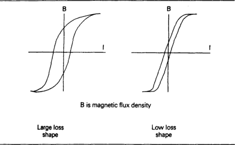
Figure 5.8 Hysteresis curves and dissipation. The area enclosed by the hysteresis curve is a measure of the energy dissipated each time the material is magnetized and demagnetized.
All of the above omits any mention of the other major cause of dissipation, the resistance of the wire which is used to construct an inductor. The ratio of reactance to resistance for an inductor is never so very high that the resistance can be neglected, so that the power factor for an inductor is never negligible as it so often is for a capacitor. In addition, the DC resistance of a wire may not be the factor that determines dissipation for signals, because at the higher frequencies signal current flows on the surfaces of wires rather than internally, so that the equivalent resistance becomes greater. In the frequency range up to about 100 MHz, inductors are wound with stranded wire, known as ‘Litz’ wire (an abbreviation of Litzendraht), whose surface area is considerably greater than that of a solid wire of equivalent cross-section. In the frequency range of approximately 100 MHz upwards inductors usually consist of self-supporting coils of thick copper which have been silver plated to increase the conductivity for surface currents. The ‘goodness’ of any inductor at a particular frequency can be assessed from its Q factor, equal to the ratio of reactance to resistance, but this is an approximation only and does not hold true as the frequency of self-resonance of the inductor with its own stray capacitance approaches.
At the highest frequencies for which separate inductors are used, inductors are more likely to consist of pieces of straight wire or metal strip rather than wound coils, and at such frequencies tuned-line theory is more useful than the resonance of inductor and capacitor. Our uses of inductors as separate components are therefore confined to lower frequencies and to a limited range of applications. In much modern equipment, signals are generated using crystal control and make use of harmonics of the crystal frequency rather than of the variation of a resonant circuit by altering either capacitance or inductance. The main uses of inductors are then as high impedances (chokes) for signals in simple filtering circuits. For more elaborate filtering, it is likely that filters based on resistor–capacitor circuits (for broad bands) or on surface-wave devices (for narrow bands) will be used.
Inductors in the range 1 μH to 1 mH can be bought as stock items, with an inductance tolerance of 10%. The inductance values are commonly measured at 100 kHz, and typical resistance values range from 0.04 Ω for the 1 μH inductor to 30 Ω for the 1 mH component. This corresponds to Q values in the range 15–21 at 100 kHz, but since reactance increases with frequency so also does the Q, value, so that Q values for these inductors are usually quoted at higher frequencies that are still well below the frequencies of resonance. Typical resonant frequencies range from 190 MHz (Q quoted at 15 MHz) for a 1 μH inductor to 3 MHz (Q, quoted at 800 kHz) for a 1 mH inductor. The maximum permitted DC is also quoted, but more from the point of view of dissipation than for change of inductance value. The core material that is used is a ferrite type so that eddy current losses are negligible and hysteresis losses are low. Since the values are non-adjustable, these inductors are best suited for use in filter circuits and as RF chokes for power supplies, etc.
Winding small inductors
Despite the availability of ready-made inductors for choke uses, there is still a need to wind inductors to specific purposes. The first decision that has to be made is whether or not to use a core. This can easily be settled by reference to the cores that are available, and very often the only cores that are widely available will be of the general-purpose type intended for frequencies up to about 2 MHz. For appreciably higher frequencies, then, the use of an air-cored coil is more likely, and since formers for coils can be used with or without cores (cores are usually sold separately) the procedure for designing the coil is much the same. The approximate inductance of the coil needs to be known, and if a core is to be used, its relative permeability under the working conditions will also need to be known. If a core is to be used, the inductance of the coil itself will be the required final value (with core) divided by the relative permeability value.
The inductance of a single layer solenoid (a coil whose length is considerably greater than its diameter) is given approximately by the formula in Figure 5.2, of which the most important feature is that inductance is proportional to the square of the number of turns. The importance of this is that if turns have to be removed or added in order to adjust the final (measured) value of inductance then the square law must be taken into account. For example, suppose that a 75-turn coil has been constructed on a former in order to achieve an inductance of 70 μH, but the measured value turns out to be 80 μH. The correct number of turns then has to be found from:
Where X is the correct number of turns. In this example, this makes the correct value of X equal to about seventy turns, so that five turns have to be removed. When a coil is wound, it can be useful to keep some spare wire in a straight length in case extra turns have to be added.
The usual problem, however, is to find the number of turns that will have to be wound in order to provide a required value of inductance, and this is always difficult because it requires you to know in advance the radius and length of the finished coil. One method is to make the winding on a standard former, always to the same length, achieving the correct number of turns by using a suitable gauge of wire. This means that the ratio of length to radius can be fixed, and allows the use of the formula illustrated in Figure 5.9.
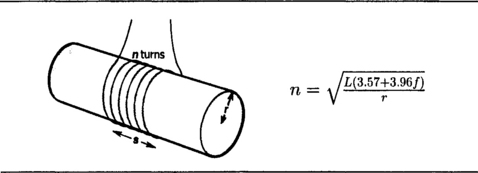
Figure 5.9 Approximate formula for the number of turns required for a given inductance value, assuming a single layer coil. Dimensions s and r are in units of mm and F = s/r.
This is an approximation, and for coils whose final value will be provided by the use of a core the approximation should always be close enough to allow the value to be corrected by altering the position of the core. For air-cored coils, the value is likely to be critical only if the coil is part of a tuned circuit, so that correct tuning can be achieved by the use of a capacitive trimmer. For some coils, the required length might be achieved only by spacing the turns, and if uninsulated wire is used (such as the silver-plated wire for high-frequency use) then spacing is essential for insulation. Even spacing can be achieved by winding two lots of wire (which need not necessarily be of the same gauge) together and then unwinding one of the coils.
When a core is to be used, then its relative permeability must be known. This could be a very difficult matter for some materials, but the ferrite materials that are used almost exclusively for signal-current inductors have more reliable values of permeability than the steel-based cores that are used for transformers. Manufacturers of cores deal with the permeability specification in two ways. For the small threaded cores that are used along with plastic coil formers, values of initial and working relative permeability are quoted. The initial relative permeability value is an indicator of the type of material, and is usually the highest possible relative permeability value that can be obtained. The working (or coil-permeability) value is the relative permeability value that can be assumed for use with a coil, and is considerably smaller. Typical values are 250 for initial relative permeability and five for working relative permeability. The optimum frequency range for the core will also be quoted. Use of the coil is not restricted to this range, but it does provide a guide to the region in which the core losses will be lowest.
The alternative approach applies in particular to coil formers which are almost entirely constructed from ferrite material, so that the coil is enclosed by a magnetic path, inside and outside. This makes the effect of the core rather more predictable, and for such coils, the manufacturers of core provide a formula and a set of values which will allow the inductance to be calculated to within quite close limits. The usual type of formula is of the form illustrated in Table 5.1, in which an inductance factor is quoted for each type of core, and the number of turns is found from the formula – note that in such formulae the inductance is usually required in nanohenries, 10−9 H. An alternative is to show the number of turns for 1 mH inductance, so that the number of turns for any other value can be found by using the relationship that inductance is proportional to the square of the number of turns. For example, if the number of turns for 1 mH is given as 63, then for 2 mH the number of turns is:
Table 5.1
Typical formulae for enclosed-core inductors – the quantities in the formula will vary from one core type to another and must be obtained from the manufacturer
Core factors can be quoted in terms of inductance per turns (squared), or as number of turns for 1mH. Whichever method is used, either a square or a root will be required. Note: 1000000 nH = 1 mH.
Example: A core is rated at 250 nH/turn2. Find the number of tums needed for an inductance of 2.5 mH.
Divide 25 mH by 250 nH, giving 100000. Take the square root, which is 316. the required number of turns.
Example: A core is rated at 63.25 tums for 1 mH. Find the number of turris needed for 32 mH.
The required inductance is 32 times 1 mH. and will need ![]() times the number of tums. which is 357.8. This would be rounded up to 359 or 360.
times the number of tums. which is 357.8. This would be rounded up to 359 or 360.
This would be rounded to 100 turns. Much higher values of effective relative permeability can be obtained in coils of this enclosed type, typically 100–200. The temperature coefficient of relative permeability will also be quoted; this is usually in the range 150–250 ppm/°C.
Enclosed coils are particularly suitable for inductors in the 1 mH and above range for frequencies of 1 kHz to 1 MHz approximately. This covers the important audio filter range, along with various modulation and subcarrier frequencies used in telecommunications. The use of adjustable cores allows for tuning with the inductor so that no capacitive trimmers are required. The inductance formulae normally assume that no DC will be applied, and that the signal currents in the coil will not take the magnetic material anywhere near its saturation point. The saturation value of flux density is often quoted, but it is by no means simple to find how this corresponds to current in the coil. One useful guide is:
Where Bsat is the saturation flux density in units of teslas, L is self-inductance in henries, I is current in amperes, A is the area of cross-section of the core in m2, n is the number of turns in the coil, and μr, is the working relative permeability.
Manufacturers often quote the effective area of cross-section for a core in terms of square millimetres, and the values of self-inductance in millihenries, with current in milliamperes, and substituting these units gives the same equation with no correction factors required. For example, for a core of effective cross-sectional area 40 mm2 and a coil of 1 mH, using sixty-three turns, the saturation flux density is quoted as 250 mT (250 × 10–3 teslas) and effective relative permeability as 170. This makes the saturation current value 630 mA, but this is purely a guide, and it would be unwise to approach anywhere near this value of signal or DC current – a good working guide would be to keep to below 10% of this value. The reason that any more precise calculation is difficult is because there is no exact relationship between inductance value and flux density unless the coil and core are of a very simple geometrical shape (like a ring), and the assumption has been made that the permeability of the core at the saturation flux value is equal to the permeability of free space.
Measuring inductance
Because winding inductors to precise values is so difficult, the measurement of inductance is important, and the standard method is some form of measuring bridge. This uses a circuit such as that shown in Figure 5.10 to obtain a balance point at which there is no signal at the detector. The value of the inductance and its resistance can then be calculated or, as is more likely in modern equipment, read from dials or digital displays. A bridge measurement is only as good as its standards, so that the bridge should contain standard inductors which are to a close tolerance, although for many purposes, an inductance value that is correct to about 10% is sufficient, since final adjustments will always be made using core movement or by the use of a trimmer capacitor.
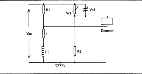
Figure 5.10 A form of measuring bridge for inductance in which an unknown inductance value is compared with a known value.
The problem here is that many of the low-cost bridge instruments do not allow for measurements on the range of inductors for which measurement is likely to be needed. Small bridges generally have a range of inductance measurement of about 1 mH to 100 H, and measurement is most likely to be needed for the range of 5 μH to 5 mH. The type of automatic bridge, such as the range made by Wayne-Kerr, can cope with measurements in this range with a resolution of 1 nH, and a precision of ±0.5 μH, using a frequency of 1 kHz or 10 kHz. If inductance measurements are the only bridge measurements that are required, and they are not required so often as to justify a costly instrument, then a simple bridge circuit can be used, or a bridge bought which is specifically for the measurement of inductances in the 1 μH to 1 mH range. A useful, but slower, alternative is to put the inductor in parallel with a value of capacitance that will swamp stray capacitance values (500 pF or more) and find the resonance frequency, then calculate the inductance from this value.
Transformers
Transformers make use of the effect of mutual induction, whether they are the multiple winding type of transformer or the autotransformer, in which one single winding is used, with connections tapped for different connections. The main types of transformers that are used in modern electronics circuits are:
1. Mains transformers, used in power supplies.
2. Matching transformers, used for feeding lines.
3. Tuned transformers, used in signal amplifiers to achieve a specified bandwidth.
Of these, the tuned transformers are seldom used now, having been replaced by combinations of wideband ICs and electromechanical filters, so that we shall confine our attentions to the mains and the signal-matching types.
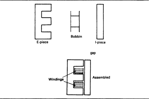
The transformer, other than the autotransformer type, has at least two windings, one of which is designated as the primary winding, the other as the secondary, and the action is that an alternating voltage applied to the primary winding causes an alternating voltage to appear at the secondary. Unless the transformer is intended only for purposes of isolation, the primary and secondary voltage levels are usually different. The conventional style of transformer consists of a bobbin on which both primary and secondary windings are formed, usually with a metal foil layer between the windings to act as an electrostatic screen. The core is then assembled by placing E and I sections of thin steel alloy into place, with the bobbin lying in the arms of the E section (Figure 5.11). There are, however, several other forms of construction. When twin bobbins are used side by side, the electrostatic screening can often be dispensed with, and some transformers make use of a pair of C-shaped cores rather than the E and I structure. Another form, very common now, is the toroidal transformer, in which both windings are placed over a ring of magnetic material. The toroidal type has in the past been very expensive to produce because of the difficulty of winding the turns into place, but development of toroidal winding machinery has made these transformers much more readily available. Their main advantage is that they have a very low external magnetic field, so that they are often specified for use in equipment where hum pickup must be kept as low as possible.
A perfect transformer can be defined as one in which no power is dissipated, so that the power supplied to the primary winding (primary voltage × primary current) is exactly equal to the power taken from the secondary (secondary voltage × secondary current). Only very large transformers approach this state of perfection, and for the sizes that are encountered in electronics the efficiency of a transformer, defined as:
will be of the order of 80% to 90%. For many purposes, however, the power loss in a transformer is not particularly important provided it does not cause the transformer to overheat.
Another equivalent definition of perfection in a transformer is that all of the magnetic flux of the primary winding will cut across the secondary winding. This leads to another way of defining transformer losses in terms of ‘leakage inductance’, meaning the portion of the primary inductance which has no effect on the secondary. Leakage inductance is more commonly used to define losses in a signal-carrying transformer than for a mains type, particularly since irregularities in the response of a transformer to wide-band signals are usually caused by leakage inductance and its resonance with stray capacitances.
As a result of the zero-power-loss definition of a perfect transformer, there is a simple relationship between the voltages and a number of turns at primary and secondary respectively, which is:
assuming that the self-inductance of the primary winding is enough to form a reasonable load in itself, because if the primary self-inductance is too low, the efficiency of the transformer will also be very low. In general, the higher the ratio of reactance to resistance for the primary winding, the more efficient the transformer is likely to be.
For all types of transformers other than autotransformers, the isolation between primary and secondary windings is important. Transformers that are specifically designed for isolation will include a DC voltage isolation test as part of the specification, and for such purposes it is normal for the insulation to be able to withstand several kilovolts DC between the primary and secondary windings without measurable leakage. The insulation from each winding to ground (the core or casing of the transformer usually) should also be of the same order.
Some types of transformers can be used with direct current flowing, and for such transformers the maximum amount of DC is stated, because excessive current could cause saturation. Saturation of the core means that the relative permeability will be reduced almost to the value for air, so that transformer action will be almost lost, and this is usually avoided by having an air gap in the core (see Figure 5.11), thus restricting the amount of flux (see earlier in this chapter). A few transformers are designed (see the telecommunication type, below) so that the core will saturate on overload so as to prevent excessive signal being passed to the secondary circuit, and some types of transformer use the same principle to distort signals for wave-shaping purposes.
Signal-matching transformers
A few types of signal-matching transformers can be bought ready-made. These include 600 Ω line isolating transformers which are used to isolate telephone users’ equipment, particularly mains-connected equipment such as facsimile (fax) equipment and computers, from the telephone lines in order to ensure that it would be impossible for mains voltage ever to be connected to the telephone line. Such transformers must be obtained from sources who can guarantee that they are constructed to standards approved by the telephone company; in the UK the relevant specification is HED 25819. These telecommunications isolating transformers are of 1 : 1 turns ratio, and an overload on the consumer’s side of the winding will fuse the winding rather than cause high voltages to be passed to the telephone lines. This happens because an overload saturates the core so that it becomes totally inefficient as a magnetic coupling between primary and secondary.
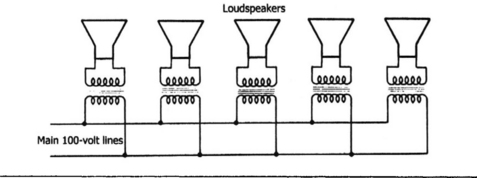
A very common type of signal-matching application is for ‘100 V line’ transformers for public-address systems. Because the power loss of audio signals on long cables is proportional to the square of current, the output of an amplifier for public-address use is usually at a standard level of 100 V for full rated power, so that the current is comparatively low. Since loudspeakers generally have impedances in the 3 Ω–15 Ω range, a matching transformer is needed for each loudspeaker (Figure 5.12). Matching transformers of this type have a selection of secondary tapping points so as to allow the use of loudspeakers of various impedance ratings, and the power handling can be from 1 W to several kW.
• US readers should note that the use of the word ‘line’ in this context has no connection with power lines.
Another audio application for a matching transformer is the microphone transformer which is intended to match a low-impedance microphone into a high impedance amplifier. General-purpose matching transformers of this type are designed for moving-coil microphones in the impedance range 20 Ω–30 Ω, or dynamic microphones in the 200 Ω–600 Ω region, and more specialized types can be obtained for ribbon microphones, usually from the manufacturers of the microphones. The primary winding of a microphone is usually centre-tapped so that the microphone cable can be balanced around ground, as illustrated in Figure 5.13, greatly reducing hum pickup, and the whole transformer is encased in metal shielding to minimize hum pickup in the transformer windings.

The other standard forms of signal transformer are pulse transformers, which are intended to transmit pulse waveforms between circuits that may be at very different AC or DC levels, such as thyristor circuits. There is no requirement for such transformers to carry low-frequency signals, and their leakage inductance also is of little importance, so very small units can be used, subject to the insulation resistance being sufficient. A typical requirement is for a voltage test to 2.8 kV peak for a transformer intended to work in the bandwidth of 3 kHz to 1 MHz. A factor that is often quoted for these pulse transformers is the voltage–time product, meaning the product of output pulse amplitude (in volts) and pulse duration (in microseconds). This product, typically 200 V μs is a way of ensuring that the transformer does not suffer from excessive dissipation from pulse signals. Pulse transformers of this type can be obtained with 1 : 1 windings, 1:1 + 1 (two secondaries, or centre-tapped secondary) or 2: 1 + 1 ratios. Primary inductance levels are in the range 3–12 mH with leakage inductance values of 8–30 μH. These transformers can be obtained as open or fully encapsulated units according to requirements.
For other requirements, particularly RF line to amplifier matching, the transformers have to be constructed to specification. In some cases, a simple tapped winding (autotransformer) will be sufficient; for other applications a transformer may have to be made to a very strict specification. Some of the most useful information on such transformers and on wound components generally is contained in the amateur radio handbooks, either from the RSGB in the UK or the ARRL in the USA. The US manuals have the advantage of containing information on circuits that operate at frequencies and power levels which cannot legally be used by amateurs in the UK.
Mains transformers
Most of the mains transformers that are used for electronics purposes are for power supplies, and as such conform to a fairly standard pattern. These transformers use laminated cores, and the older types use the familiar I and E shaped core pieces which can be fitted together with an air gap. The size of this air gap is a very important feature of the transformer, and is the reason for the difficulties that many users experience when they rebuild a transformer for another purpose, such as rewinding the secondary for a different voltage. The air gap acts for the magnetic circuit of the transformer as a high resistance would in a current circuit, and its magnetic effect is to restrict the magnetic flux in the core. This greatly reduces the likelihood of saturating the core with the large amounts of current that flow in the windings. An air gap is particularly important for mains frequency chokes in smoothing circuits which are likely to carry DC as well as AC ripple, but the use of chokes for this purpose is by now rare.

Figure 5.14 The principle of the toroidal winding, which is much more efficient for concentrating flux.
The traditional I and E, or C, core, however, is not ideally suited to all types of transformer requirements, particularly those which demand a low level of magnetic field around the transformer. A simple solution to the requirement for low external magnetic field is the toroidal transformer, which has become much more generally available thanks to the development of efficient toroid-winding machines in the last twenty years. The main point to note about toroidal transformers is that it can be only too easy to ruin their performance by incorrect mounting, because it is possible to make the mounting form a metal path which is in effect a shorted secondary turn which will dissipate a large part of the energy of the transformer.
The specifications for mains transformers reflect the normal use of such transformers with rectifiers and capacitors to form power supplies. The most important rating is the volt-amp rating (VA) for each secondary winding, expressing the maximum current that can be drawn at the winding voltage. The name volt-amp is used rather than watt because the use of watts would imply a power factor of unity. Because the transformer is not 100% efficient, the volt-amps at the primary will be greater than the sum of the volt-amps at the secondary windings, and part of this, although seldom stated directly, is often implied in a figure for ‘magnetizing current’, meaning the current which flows in the primary when no load is connected to any secondary winding.
• Modern power supplies make use of active circuits with the aim of keeping the load current in phase with the load voltage and minimizing spikes and harmonics. These techniques are beyond the scope of this book.
• A very common practice now is to provide mains transformers with two primary windings rated at 110 V so that the transformer can be used with paralleled inputs on 110 V supplies or with series connections on 220 V.
The regulation of a transformer is an important factor in its use for power supply circuits. When the transformer is loaded by a rectifier and smoothing circuit, and full rated current is being drawn from the secondary (or from each secondary if there are several windings), then the regulation is the fractional drop in voltage, defined as:
and expressed as a percentage. The regulation percentages can be very large for small transformers, typically 20% of a 3 VA type, falling to 5% or less for the larger transformers of 200 VA or more. Some manufacturers quote open-circuit and full-load voltage levels rather than regulation. One important point to watch is that many manufacturers quote the full-load figure for secondary voltage output. This means that for a small transformer with poor regulation, the open-circuit voltage can be as much as 20% higher, and allowance must be made for this in the circuits which are connected to the transformer. Unless voltage stabilization is used, this order of voltage change between no-load and full-load may be unacceptable for applications that involve the use of ICs.
For any transformer, it is important to have some knowledge of the likely temperature rise during full-load operation. This figure is not always quoted, and an average for the larger transformers is 40°C above ambient for each winding (although most of the temperature rise originates in the secondary windings). Smaller transformers can have greater temperature rise figures, typically 60°C. The maximum acceptable temperature of a transformer is often not quoted and should not exceed 90°C unless the manufacturer specifies another figure. Transformers that use class E insulation can be run at a maximum working temperature of 120°C, but this figure is exceptional among the usual range of transformers for power supplies. The full rating for a transformer implies a 25°C ambient, and the manufacturers should be consulted if higher ambient temperatures are likely.
Since transformers are subject to high peak voltages, the sum of AC and DC voltages, there is a figure of proof voltage (otherwise known as flash test voltage) for each transformer type which is at least 2 kV. This measures voltage breakdown between windings and also between each winding and the metal core. The higher grades of transformers will be tested to higher proof voltages, typically at 5 kV sustained for one minute, and transformers that are intended for special purposes such as heater supplies to cathode ray tubes whose cathodes are operated at very high voltage (negative voltages) will have to be tested to considerably higher voltages. The low voltage requirements of modern instrument CRTs, however, imply that such transformers are seldom required now other than for servicing of old instruments.
The winding resistance of a transformer is not often quoted, although secondary winding resistance is an important factor when designing a power supply whose regulation (before the use of a stabilizing circuit) needs to be known. Note that transformers intended for 60 Hz supplies should not be used in 50 Hz applications. Where winding resistance values are quoted, both primary and secondary will be quoted, and a typical primary resistance for a 240 VA transformer is 4 Ω, with higher values for the smaller transformers. Secondary resistances for low-voltage windings are much lower, of the order of 0.05 Ω for a winding rated at 10 A, higher for windings of lower current rating or for high-voltage windings.
The overwhelming majority of transformers for power supply use have secondary windings that are rated for voltages up to 20 V rms, although because secondaries are often wound with a view to bi-phase rectification (see below), a 20 V secondary will actually consist of two 20 V connected windings, i.e. a 40 V winding with a centre-tap. The output voltage and current that can be obtained depend on the form of rectification and smoothing circuits that are used. When the rectifier circuit is followed by a large reservoir capacitor (capacitive input filter), then the DC output voltage of the circuit is high but the current regulation is poor. When a choke input filter is used (the rectifier circuit is followed by a series inductor) then voltage output is lower but current regulation is better.
Figure 5.15 shows the usual standard rectifier and filter circuits, along with the relationship between AC output voltage and DC output voltage and between AC current and DC current. Only capacitor input smoothing has been shown here, because the use of an inductor immediately following rectification (inductive input filter) is very unusual nowadays. The inductive input filter has advantages of better regulation, but the size, cost and weight of the inductor makes the system less attractive, particularly when a voltage stabilizer is likely to be used in any case. Most power supply units use the bridge rectifier arrangement along with a capacitive input filter (reservoir capacitor). When a capacitor input filter is used, the capacitor must be rated to take the full amount of ripple current. As a rule of thumb, the ripple current can be taken as the difference between the AC current and the DC current.

Figure 5.15 The standard rectifier filter circuits and approximate performance formulae, ignoring rectifier losses, ripple, and resistance losses.
For unusual secondary voltage requirements, it is possible to buy transformer kits, in which the primary winding is supplied on its bobbin, but the secondary has to be wound, and then the bobbins assembled on to the core. These transformer kits are usually of the conventional E and I core type, but several manufacturers supply toroidal cores with a primary winding already provided, and these are particularly useful for very low-voltage supplies which require only a few turns of secondary winding. For each size of core, the manufacturer will quote the number of secondary turns per volt of output, typically from two turns per volt for the 200 VA size to six turns per volt for the 20 VA size.
The wire provided in these kits is the conventional enamelled copper, and the range of diameters is around 0.2 mm to 2.0 mm. When you select a wire gauge for a secondary winding you should bear in mind the power dissipation heating that you can expect at full rated current. For applications needing more than 10 A you will need to use wire of more than 2.0 mm diameter.
• Remember the rule of thumb that you need at least 1000 μF of reservoir capacitor per ampere of output current. Remember also that the rms current in the transformer windings is substantially more than the output DC current.
For details of transformer kits in the UK, see the ElectroComponents catalogue, or the international website at
You can register at the website to receive information about components, and updates of the product list and technical information.
Other transformer types
Isolation transformers use a 1 : 1 winding ratio and are intended to permit isolation from the mains supply. One important application is in the servicing of the older type of TV receivers, in which one mains lead was connected to the metal chassis. Although this ought to be the neutral lead, there can be no certainty of this, particularly when a twin lead is used with no colour coding. By using an isolating transformer, the whole chassis can, if required, be grounded, or it can be left floating so that there is no current path through the body of anyone touching any part of the circuit unless another part of the circuit is touched at the same time. Isolation transformers are also used for operation of power tools in hazardous situations (outdoors and in very humid surroundings), and some types can be bought already fitted with the standard form of splashproof socket for outdoor use, along with a ground-leakage contact breaker.
Autotransformers consist of a single tapped winding, so that they offer no isolation, unlike the double-wound form of transformer. Fixed ratio autotransformers are intended to allow the use of electrical equipment on different mains voltages, for example the use of US 110 V equipment on European 220 V supplies. The demand for this type of transformer in the UK tends to be localized around US air bases, but there is a large amount of test equipment in use which demands a 115V supply and which has to be supplied by way of an autotransformer. It is important to ensure that any such equipment cannot under any circumstances be accidentally plugged into 220 V mains, and a fuse should be incorporated to prevent damage in the case of an accidental overload. Autotransformers can also be used to provide 220 V for European equipment being used in a country where the supply voltage is 110 VAC.
The more common type of autotransformer is the variable type, such as the well-established Variac (trademark of Claude Lyons Ltd). This consists of a single toroidal winding with the mains supply connected to one end and to a suitable tap (the taps provide for different mains voltage levels), and an output terminal which is connected to a carbon brush whose position on the winding can be varied by rotating a calibrated knob. This allows for an output to be obtained whose voltage can be smoothly varied from zero to a voltage greater than the mains supply voltage, typically 270 V. Current ratings range from 0.5 A to 8 A depending on the size of toroidal core that is used. Variable autotransformers can be obtained either in skeleton form, with virtually no protection from the windings or connections, or in various degrees of enclosure. Since these are autotransformers there is no mains isolation, and if isolation is needed, it must be provided by a separate isolating transformer used to feed the autotransformer.
Magnetic amplifiers
The characteristics of a material being magnetized, shown in the drawing of Figure 5.6, can be used as the basis of an amplifier. Normally, for transformer action, we try to use a core material where the characteristic resembles as closely as possible a straight line, with minimum change of slope and smallest possible area of loop. It is possible, however, to make core materials which permit a wide range of characteristics, including some which reach saturation (the point at which the magnetization due to the core has reached maximum). An inductor wound on such a core is called a ‘saturable reactor’, and its inductance will vary according to the extent to which the core is saturated, Figure 5.16.
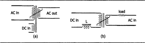
Figure 5.16 (a) Principle of saturable reactors. (b) Control of AC in a load by the direct current through a saturable reactor.
If a transformer is wound on such a core, together with a third winding, then, with no current flowing through the third winding, normal transformer action will take place provided that the core is not saturated by the primary current. If DC is now passed in the third winding, the core will come closer to saturation, the primary inductance will be lower and the coupling less so that the output will drop. With the core completely saturated, the output is almost zero. This can be made the basis of an amplifier circuit which consists of reactors only. The operating power is AC, and the ‘signal’ controlling the amplifier is DC or very low frequency AC. Very high gain figures can be achieved, for a low-voltage passing current in the control winding can control a high-voltage high-current AC, which if necessary can be rectified and used as the DC control signal in another amplifier. Magnetic amplifiers are extremely reliable and are used in industrial control circuits where speed of response is not important, particularly in motor control circuits. They are generally bought as a complete package, sometimes designed to order by the transformer manufacturer, and seem to be almost unknown outside the specialized fields in which they have been used.
Switch-mode supplies
The traditional approach to the design and construction of a stabilized supply is in many ways far from ideal. To start with, a large amount of energy is wasted because the unstabilized output level has to be maintained considerably greater than the stabilized level, and the voltage difference will result in considerable dissipation of heat from the stabilizer. At low voltage levels in particular, very large values of capacitance are needed for the reservoir, and this demands electrolytics of 100 000 μF to 500 000 μF, with all of the problems that attach to electrolytics. The low frequency of the ripple from a mains-operated supply is always difficult to remove completely, even using large capacitors, unless the voltage level is high enough to allow inductors with their inevitable series resistance to be used.
The answer to many of the problems of making high-current low-dissipation low-voltage supplies is the use of switch-mode supplies, which exist in several types. Although these circuits contain both active and passive components, their action makes use of several types of passive components in a way that needs to be understood if you are involved in specifying or servicing such equipment. The types that are used for applications such as TV receivers use the mains at full voltage to provide power for an oscillator whose output in turn is rectified and stabilized. Another option, used particularly for digital equipment, is to employ a step-down transformer to provide mains isolation, rectifying the output of this transformer to use as the supply to the switch-mode circuits. When this latter approach is used, the circuit can provide for a step-down or a step-up of the DC voltage applied to the chips, using an inductor when a step-up is needed. These circuits also generally make use of higher frequencies for operation.
The more modern form of switch-mode power supply is illustrated in the block diagram of Figure 5.17. The mains voltage is rectified, using a bridge set of diodes connected directly across the mains, and this output is partially smoothed. The rough DC is used to operate an inverter oscillator whose output is connected to a high-frequency transformer – a typical frequency is 50 kHz so that the transformer can be a comparatively small and light component. All stages up to and including the primary of this transformer are live to mains.
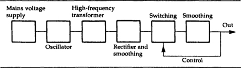
Figure 5.17 A block diagram for a modern form of switch-mode supply, using a high-frequency oscillator and transformer.
At the secondary of this transformer, low-voltage windings can be used, and these will not be live to mains. The output from a winding can be rectified, using a bridge circuit, and smoothed using comparatively low-value capacitors. For low-current lines, a conventional IC stabilizer circuit can then be used, but more usually a switching circuit will be used, chopping the DC into square waves whose mark–space ratio (ratio of high-voltage time to low-voltage time) can be controlled by a voltage-controlled oscillator. This square waveform is again smoothed into DC, and the level of this DC is used to supply the control voltage for the switching circuit. In this way, stabilization is carried out with minimal loss of power, because the switching circuits will be either fully conductive or fully cut off, and changes in the stabilization conditions do not cause large changes in dissipation.
Heat-sink requirements are negligible, and the design of the circuit makes it easy to include cut-off provisions in the event of overvoltage, overcurrent or overheating. In this form, however, the circuit contains some redundancy in the sense that smoothing is being done twice and the square wave formation is being carried out twice, once in the inverter stage and again in the switching stage. The benefits are precise control of low-voltage high-current supplies, with smaller and lighter components (particularly inductors and capacitors), and with ripple at a frequency which is easily smoothed.
An alternative, still preserving the mains-voltage approach, is to control the inverter part of the circuit which operates at mains voltage. Figure 5.18 shows the block diagram for a circuit which uses an opto-isolator circuit for this purpose. The usual mains-level bridge rectifier and reservoir circuit operates an inverter whose mark–space ratio can be controlled by a DC signal. The output of the inverter is converted to the correct voltage level using a high-frequency transformer as before, and this is rectified and smoothed. The smoothed output is used to control the inverter by way of an opto-isolator acting to supply the DC control voltage from the inverter using as its input the DC output from the stabilized voltage. In this way, the output side of the circuit is not at mains voltage, but can still be used to exert control on the inverter circuit which is at mains voltage.

Figure 5.18 Another form of switch-mode supply in which control is exerted on the oscillator by way of feedback through an opto-electronic link.
This approach is comparatively simple in block form, but because of the losses in the opto-isolator it can require rather more circuitry than might appear to be needed. Another problem is that some regulatory bodies concerned with electrical safety do not consider opto-isolators as suitable for total insulation between mains supply and the chassis of electronic equipment. The problem is that most opto-isolators have only a small separation between input and output, less distance than is stipulated to be used between live parts in electrical safety regulations.
The use of pulse-transformer methods is an alternative that can more easily pass electrical safety approval tests, since a transformer can be manufactured to any required standard of isolation. In addition, the use of a pulse-transformer method obviates the need to have an inverter working at mains voltage, and substitutes in its place a pulse amplifier.
One disadvantage of all switch-mode circuits, however, is RF interference. The essence of a switch-mode supply is that large charging and discharging currents are likely to flow, and where these currents flow in stray capacitances and inductances there is likely to be resonance that can result in RF being generated. The problem is tackled firstly in the layout of the circuit by ensuring that grounding, particularly single-point grounding, is correctly carried out, and circuits are encased in metal screens to reduce radiation as far as is practicable, but from then on, filtering is required to reduce the level of conducted RF interference (RFI) to a minimum. Filtering is made considerably easier if the circuits use a mains-frequency transformer, since this prevents the spread of RFI through the mains lines. The use of a mains transformer with a grounded screen between primary and secondary, along with a 10 nF capacitor across the output terminals of the transformer, results in a reduction of conducted RFI to well below the limits imposed by regulations of bodies such as the FCC in the USA. Further reductions can be achieved by using an inductive filter on the secondary side of the mains transformer, and by filtering each output of the power supply. The usual range for testing for RFI is 10 kHz to 30 MHz, but good filtering will ensure that low levels of RFI are found for frequencies well above the 30 MHz limit.