Miscellaneous Oscillators
The sources of the following circuits are contained in the Sources section, which begins on page 173. The figure number contained in the box of each circuit correlates to the source entry in the Sources section.
Resistance-Controlled Digital Oscillator
Oscillator Adjustable Over 10:1 Range
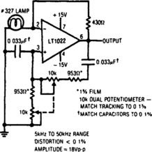
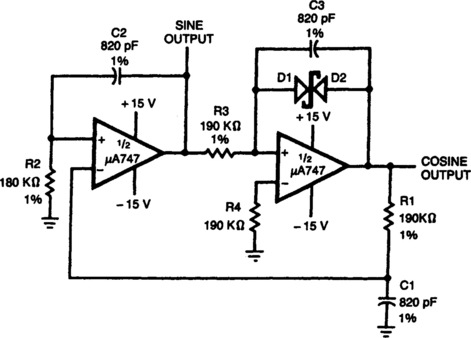
Low-Distortion Sine-Wave Oscillator
Tunable Single-Comparator Oscillator
Wide-Range Oscillator (Frequency Range of 5000:1)
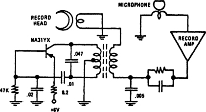
Programmable-Frequency Sine-Wave Oscillator
TUNABLE-FREQUENCY OSCILLATOR
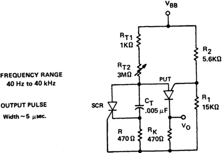
The variable oscillator circuit includes active elements for discharging the timing capacitor CT (Fig. 4-1A). A second method is given as in Fig. 4-1B.
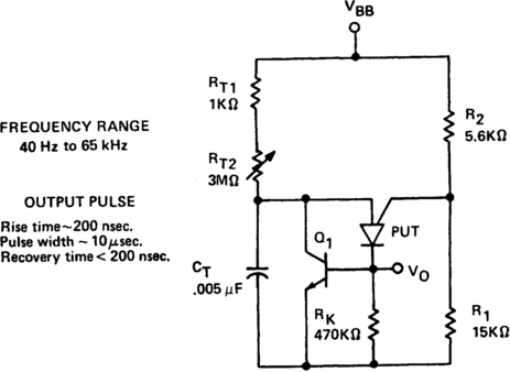
Flg. 4-1A
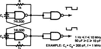
RESISTANCE-CONTROLLED DIGITAL OSCILLATOR
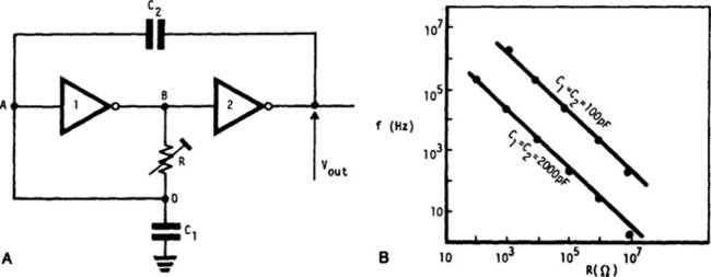
This very simple, low-cost oscillator, is built with two CMOS buffer inverters, two capacitors and a variable resistance. The circuit can work with voltages ranging from 4 V up to 18 V. If C1 = C2, the frequency of oscillation, (ignoring the output and input impedance) is given by:
The graph in Fig. B shows how the output frequency varies with resistance when C1 = C2 = 100 pF and C1 = C2 = 2000 pF.
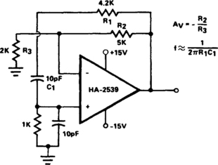
OSCILLATOR ADJUSTABLE OVER 10:1 RANGE
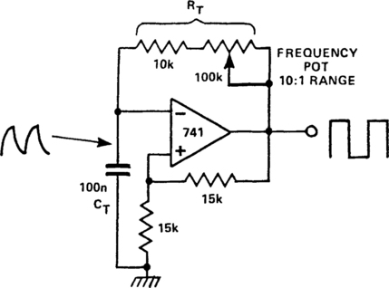
In this circuit, two feedback paths are around an op amp. One is positive dc feedback, which forms a Schmitt trigger. The other is a CR timing network. Imagine that the output voltage is +10 V. The voltage at the noninverting terminal is +15 V. The voltage at the inverting terminal is a rising voltage with a time constant of CtRT. When this voltage exceeds + 5 V, the op amp’s output will go low and the Schmitt trigger action will make it snap into its negative state. Now the output is −10 V and the voltage at the inverting terminal falls with the time constant as before. By changing this time constant with a variable resistor, a variable frequency oscillation may be produced.
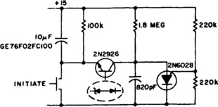
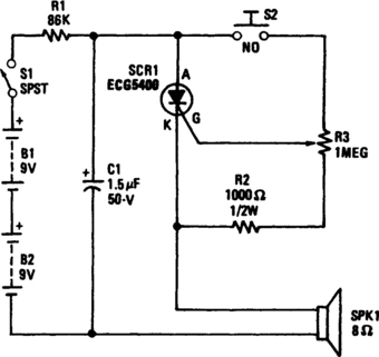
1-SECOND 1-kHz OSCILLATOR
This circuit operates as an oscillator and a timer. The 2N6028 is normally on due to excess holding current through the 100-kΩ resistor. When the switch is momentarily closed, the 10-µF capacitor is charged to a full 15 volts and 2N2926 starts oscillating (1.8 MΩ and 820 pF). The circuit latches when 2N2926 zener breaks down again.
SINE-WAVE SHAPER
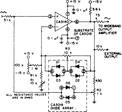
This circuit uses a CA3140 BiMOS op amp as voltage follower, together with diodes from a CA3019 array, to convert a triangular signal (such as obtained from a function generator) to a sine-wave output with typical THD less than 2%.
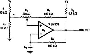
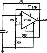
TUNABLE SINGLE-COMPARATOR OSCILLATOR
Varying the amount of this comparator circuit’s hysteresis makes it possible to smoothly vary output frequencies in the 740-Hz to 2.7-kHz range. The amount of hysteresis together with time constant R6C1 determines how much time it takes for C1 to charge or discharge to the new threshold after the output voltage switches.
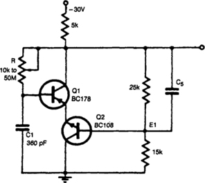
WIDE-RANGE OSCILLATOR (FREQUENCY RANGE OF 5000:1)
Timing resistor R can be adjusted to any value between 10 kΩ and 50 MΩ to obtain a frequency range from 400 kHz to 100 Hz. Returning the timing resistor to the collector of Q1 ensures that Q1 draws its base current only from the timing capacitor Ct. The timing capacitor recharges when the transistors are off, to a voltage equal to the base emitter voltage of Q2 plus the base emitter drops of Q1 and Q2. The transistors then start into conduction. Capacitor Cs is used to speed up the transition. A suitable value would be in the region of 100 pE.
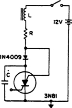
RLC OSCILLATOR
A positive transient, such as the power switch closing, charges C through L to a voltage above the supply voltage, if Q is sufficient When the current reverses, the diode blocks and triggers the SCS. As the capacitor discharges, the anode gate approaches ground potential, depriving the anode of holding current. This turns off the SCS, and C charges to repeat the cycle.
HC-BASED OSCILLATORS
Two inverters, one resistor, and one capacitor are all that is required to make a HC(T)-based oscillator that gives reliable operation up to about 10 MHz. The use of two HC inverters produces a fairly symmetrical rectangular output signal. In the same circuit, HCT inverters give a duty factor of about 25%, rather than about 50%, since the toggle point of an HC and an HCT inverter is ½ VCC, and slightly less than 2 V, respectively. If the oscillator is to operate above 10 MHz, the resistor is replaced with a small inductor, as shown in Fig. 4-11B.
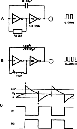
The output frequency of the circuit in Fig. 4-11A is given as about l/1.8rc, and can be made variable by connecting a 100-kΩ potentiometer in series with R. The solution adopted for the oscillator in Fig. 4-11B is even simpler: C is a 50-pF trimmer capacitor.
PROGRAMMABLE-FREQUENCY SINE-WAVE OSCILLATOR
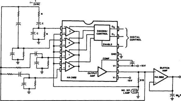
This Wien-bridge oscillator is very popular for signal generators, because it is easily turned over a wide frequency range, and has a very low distortion sine-wave output. The frequency determining networks can be designed from about 10 Hz to greater than 1 MHz; the output level is about 6.0-V rms. By substituting a programmable attenuator for the buffer amplifier, a very versatile sine-wave source for automatic testing, etc. can be constructed.
VARIABLE WIEN-BRIDGE OSCILLATOR
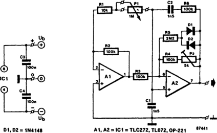
A Wen-bridge oscillator can be made variable by using two frequency-determining parts that are varied simultaneously at high tracking accuracy. High-quality tracking potentiometers or variable capacitors are, however, expensive and difficult to obtain. To avoid having to use such a component, this oscillator was designed to operate with a single potentiometer. The output frequency, f0, is calculated from:
With preset P2 you can adjust the overall amplification so that the output signal has a reasonably stable amplitude, 3.5 Vpp max., over the entire frequency range. The stated components allow the frequency to be adjusted between 350 Hz and 3.5 kHz.
50% DUTY-CYCLE OSCILLATOR
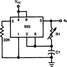
Frequency of oscillation depends on the R1/C1 time constant and allows frequency adjustment by varying R1.
HIGH-FREQUENCY OSCILLATOR
Intended primarily as a building block for a QRP transmitter, this 20-MHz oscillator delivered a clean 6-V, pk-pk signal into a 100-Ω load.
LOW-FREQUENCY OSCILLATOR
This simple RC oscillator uses a medium-speed comparator with hysteresis and feedback through R1 and C1 as timing elements. The frequency of oscillation is, at least theoretically, independent from the power supply voltage. If the comparator swings to the supply rails, if the pull-up resistor is much smaller than the resistor Rh, and if the propagation delay is negligible compared to the RC time constant, the oscillation frequency is:
WIEN-BRIDGE OSCILLATOR
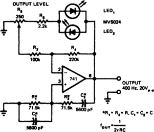
LEDs function as both pilot lamps and as an AGC (automatic gain control) in this unconventional amplitude-stabilized oscillator.
CMOS OSCILLATOR
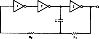
This circuit is guaranteed to oscillate at a frequency of about 2.2/(R1 × C) if R2 is greater than R1. You can reduce the number of gates further if you replace gates 1 and 2 with a noninverting gate.
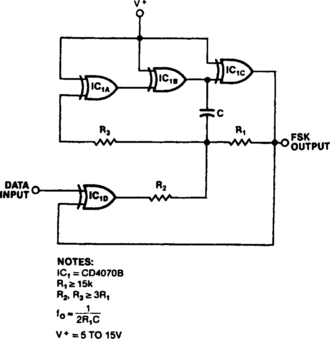
XOR-GATE OSCILLATOR
An exclusive-OR gate, IC1D, turns a simple CMOS oscillator into an FSK generator. When the data input increases, IC1D inverts, and negative feedback through R2 lowers the circuit’s output frequency. A low input results in positive feedback and a higher output frequency. R1 and C set the oscillator’s frequency range, and R2 determines the circuit’s frequency shift. To ensure frequency stability, make R3 much greater than R1 and use a high-quality feedback capacitor. The three gates constituting the oscillator itself need not be exclusive-OR types; use any CMOS inverter.
CMOS OSCILLATOR
The common clock oscillator in Fig. 4-22A has two small problems: It might not, in fact, oscillate if the transition regions of its two gates differ. If it does oscillate, it might sometimes oscillate at a slightly lower frequency than its equation predicts because of the finite gain of the first gate. If the circuit does work, oscillation occurs usually because both gates are in the package and, therefore, have logic thresholds only a few millivolts apart.
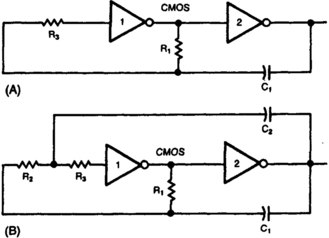
The circuit in Fig. 4-22B resolves both problems by adding a resistor and a capacitor. The R2/C2 network provides hysteresis, thus delaying the onset of gate 1’s transition until C1 has enough voltage to move gate 1 securely through its transition region. When gate 1 is finally in its transition region, C2 provides positive feedback, thus rapidly moving gate 1 out of its transition region.
The equations for the oscillator in Fig. 4-22B are:
5-V OSCILLATOR
Consistently self-starting and yet capable of operating from over 1 Hz to 10 MHz, this low-cost oscillator requires only five components. Calculate the period of oscillation by using this relationship: P=5×10³ C sec when C=C1 = C2. By changing the ratio of C1 to C2, the duty cycle can be as low as 20%.
LOW-VOLTAGE WIEN-BRIDGE OSCILLATOR
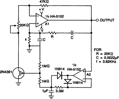
This circuit utilizes an HA-5152 dual op amp and FET to produce a low-voltage, low-power, Weinbridge sine-wave oscillator. Resistors R and capacitors C control the frequency of oscillation; the FET, used as a voltage-controlled resistor, maintains the gain of A1 exactly 3 dB to sustain oscillation. The 20-kΩ pot can be used to vary the signal amplitude. The HA-5152 has the capability to operate from ± 1.5-V supplies. This circuit will produce a low-distortion sine-wave output while drawing only 400 μA of supply current.