Voltage-Controlled Oscillators
The sources of the following circuits are contained in the Sources section, which begins on page 173. The figure number contained in the box of each circuit correlates to the source entry in the Sources section.
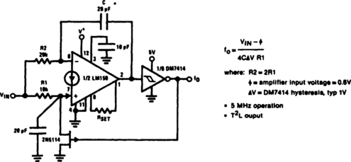
Linear Voltage-Controlled Oscillator
Voltage-Controlled Oscillator (10 Hz to 10 kHz)
Simple Voltage-Controlled Oscillator
Precision Voltage-Controlled Oscillator
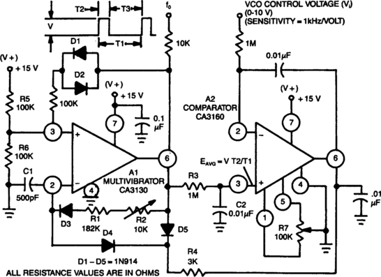
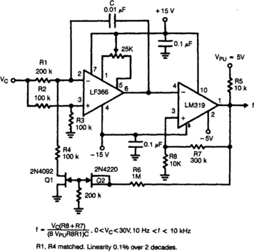
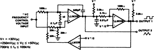
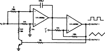
LINEAR VOLTAGE-CONTROLLED OSCILLATOR

The linearity of input sweep voltage versus output frequency is significantly improved by using an op amp.
VCO
Fig. 8-3
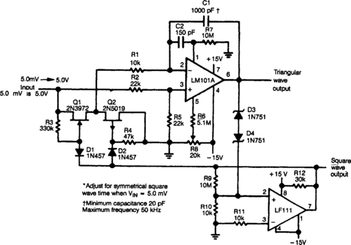
At startup, the voltage in the trigger input at pin 2 is less than the trigger level voltage, ⅓ VDD, causing the timer to be triggered via pin 2. The output of the timer at pin 3 becomes high, allowing capacitor Ct to charge very rapidly through diode D1 and resistor R1.
When capacitor Ct charges to the upper threshold voltage ⅔ VDD, the flip-flop is reset, the output at pin 3 decreases, and capacitor Ct discharges through the current mirror, TLO11. When the voltage at pin 2 reaches ⅓ VDD, the lower threshold or trigger level, the timer triggers again and the cycle is repeated.
SIMPLE VOLTAGE-CONTROLLED OSCILLATOR
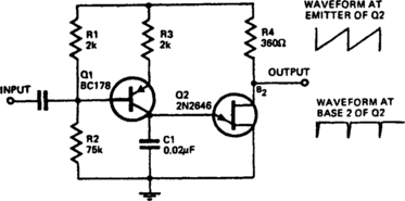
With the component values shown, the oscillator has a frequency of 8 kHz. When an input signal is applied to the base of Q1 the current flowing through Q1 is varied, thus varying the time required to charge Cl. As a result of the phase inversion in Q1, the direction of output frequency change is 180 degrees out of phase with the input signal. The output can be used to trigger a bistable flip-flop.
PRECISION VOLTAGE-CONTROLLED OSCILLATOR
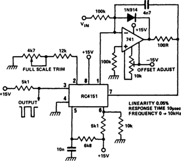
RC 4151 precision voltage-to-frequency converter generates a pulse train output linearly proportional to the input voltage.
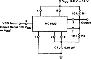
VOLTAGE-CONTROLLED OSCILLATOR
The VCO circuit, which has a nonlinear transfer characteristic, will operate satisfactorily up to 200 kHz. The VCO input range is effective from ⅓ VCC to VCC −2 V, with the highest control voltage producing the lowest output frequency.
WAVEFORM GENERATOR/STABLE VCO
In this circuit, a waveform generator is used as a stable VCO in phase-locked loop (PLL).
VARIABLE-CAPACITANCE DIODE-SPARKED VCO
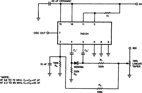
You can transform a 74S124 multivibrator into a wideband VCO by replacing its conventional fixed capacitor with a variable-capacitance diode. The only disadvantage of this scheme is the 30-V biasing voltage that the diode requires. Capacitors C1 and C2 couple the Philips BB909A variable-capacitance diode to the 74S124. R1 and R2 are large enough to isolate ground and control voltages from the timing capacitors. Resistors R3 and R4 form a voltage divide for the 74S124’s control input.
BALANCED TMOS VCO
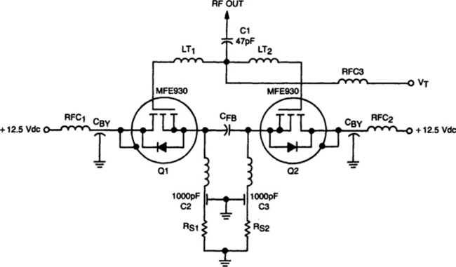
Fig. 8-10 Copyright of Motorola. Inc. Used by permission.
This TMOS VCO operates in push-pull to produce 4 W at 70 MHz. It consists of two MFE930 TMOS devices in a balanced VCO that generally provide better linearity than the single-ended types. Varactors are not used because the design takes advantage of the large change in Miller capacitance, CRSS that is available in TMOS gate structures.
In the balanced VCO, the fundamental (fo) and/or twice the fundamental (2fo) can be coupled from the circuit at separate nodes. This makes the balanced oscillator very useful in phase-locked loops. The fundamental:
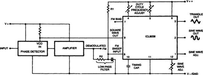
LOGARITHMIC SWEEP VCO
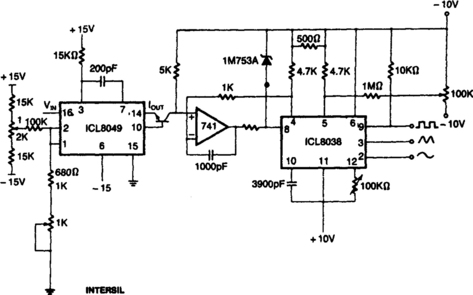
This circuit uses the output of the ICL8049 to control the frequency of the ICL3038 waveform generator; the 741 op amp is used to linearize the voltage-frequency response. The input voltage to the 8049 can be, for example, from the horizontal sweep signal of an oscilloscope; the output of the 8038 will then sweep logarithmically across the audio range. By feeding this to the equipment being measured and detecting the output, a standard frequency response can be obtained.
SIMPLE VCO
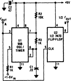
The output frequency of the VCO, U1, varies inversely with the input voltage. With a 1-V input, the oscillator output frequency is about 1500 Hz; with a 5-V input, the output frequency drops to around 300 Hz. The output frequency range of U1 can be altered by varying the values of C1, R2, and R3. Increasing the value of any of those three components will lower the oscillator frequency, and decreasing any of those values will raise the frequency. Output-waveform symmetry suffers because the frequency varies from one extreme to the other. At the highest frequency, the waveform is almost equally divided. But when the frequency drops, the output of the circuit turns into a narrow pulse. If a symmetrical waveform is required, add the second IC, U2, half of a 7473P dual TTL J-K flip-flop, to the oscillator circuit.