Sirens, Warblers and Wailers
The sources of the following circuits are contained in the Sources section, which begins on page 173. The figure number contained in the box of each circuit correlates to the source entry in the Sources section.
Programmable-Frequency Adjustable-Rate Siren
Siren Simulates Star Trek Red Alert
TWO-TONE SIREN
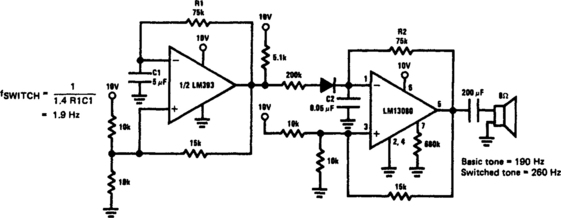
This siren provides a constant audio output, but alternates between two separate tones. The LM13080 is set to oscillate at one basic frequency; this frequency is changed by adding a 200-kΩ charging resistor in parallel with the feedback resistor, R2.
YELPING SIREN
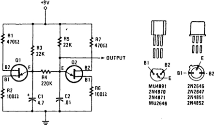
Unijunction transistors Q1 and Q2 are both connected as relaxation-type, sawtooth oscillators. Transistor Q1 is the low-frequency control oscillator and Q2 is the tone generator. Sawtooth waveforms are produced at the emitter terminals. Without R4 connecting the two emitters, each oscillator operates independently, with its frequency determined mainly by the RC time constant. With the values shown, Q1 operates from 1 to 1.5 Hz and Q2 operates from 400 to 500 Hz. When R4 is connected between the two emitters, it couples the low-frequency sawtooth from Q1 directly across capacitor C2. That coupling causes the frequency of the tone generator to increase, along with the rise in sawtooth voltage from Q1. The tone generator’s frequency drops to its lower design value when C1 discharges and produces the falling edge of the sawtooth.
SIREN
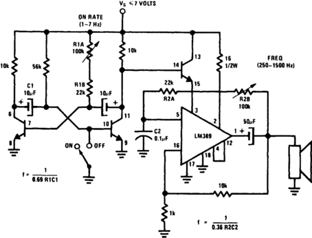
This circuit uses one of the LM389 transistors to gate the power amplifier on and off by applying the muting technique. The other transistors form a cross-coupled multivibrator circuit that controls the rate of the square-wave oscillator. The power amplifier is used as the square-wave oscillator with individual frequency adjust provided by potentiometer R2B.
TWO-STATE SIREN
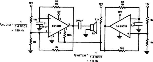
This is a two-state or on/off-type siren where the LM13080 oscillates at an audio frequency and drives an 8-Ω speaker. The LM339 acts as a switch, which controls the audio burst rate.
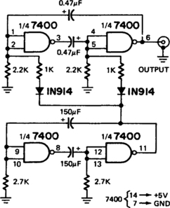
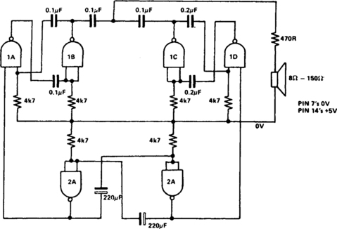
7400 SIREN
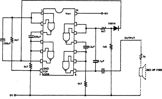
Two NAND gates are used for the oscillator, and two as the control. If the two-tone speed needs to be altered, the 220-µF capacitors can be changed (larger for slower operation). If the frequency of the oscillator is to be changed, the 0.2- and 0.1-μF capacitors can be varied and the value of R1 can be increased. To change frequency range between the two notes, alter the 1.5-kΩ resistor.
TOY SIREN
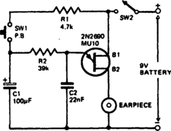
This circuit can be built small enough to fit inside a toy. The circuit consists of a relaxation oscillator utilizing one unijunction transistor (2N2646, MU10, TIS43). R2 and C2 determine the frequency of the tone. Pushing the button, SW1 charges up the capacitor and the potential at the junction of R2 and C2 rises, causing an upswing in the oscillation frequency. On releasing the pushbutton, the charge on C2 will drop slowly with a proportional reduction in the frequency of oscillation. Manual operation of the button at intervals of approximately 2 seconds will produce a siren sound.
MULTIFUNCTION SIREN SYSTEM
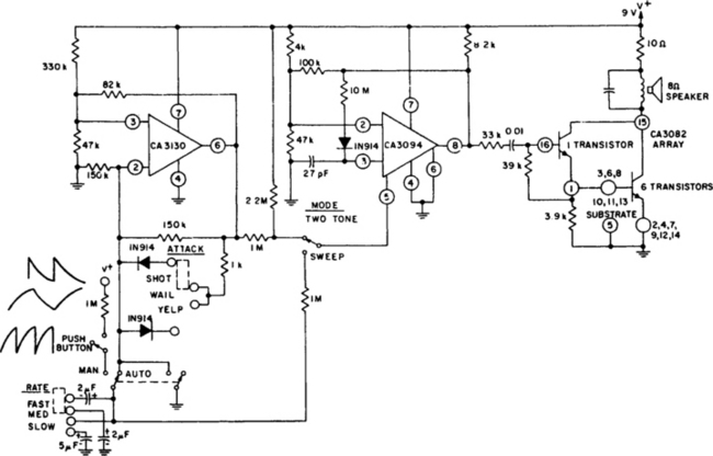
The circuit uses a CA3130 BiMOS op amp as a multivibrator to control the siren’s rate. A CA3094 used as a VCO is followed by a CA3082 transistor array to drive a speaker. A “Manual” or “Auto” mode switch allows the user to select either intermittent or continuous siren operation, respectively. In addition, three switches are available to control “Mode,” “Attack,” and “Rate.”
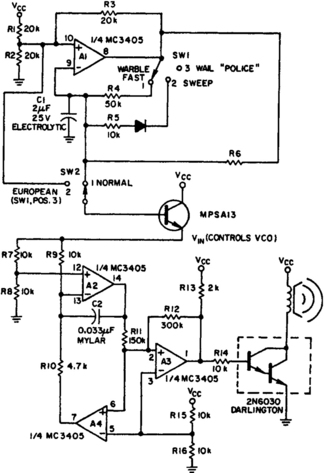
LINEAR IC SIREN
A low-frequency, op-amp oscillator and a VCO, both configured from a single MC3405 dual op amp and dual comparator, are the major components in a siren circuit that can be made to produce various warbles and wails, or serve as an audio sweep generator. The only other active components needed are an MPS A13 small-signal transistor and a 2N6030 power Darlington transistor.
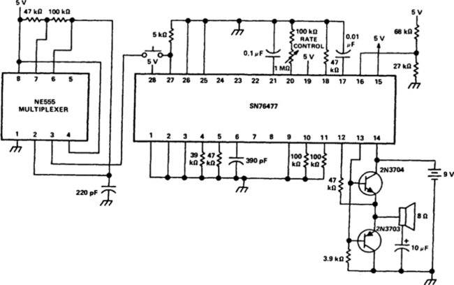
SUPER SOUND GENERATOR
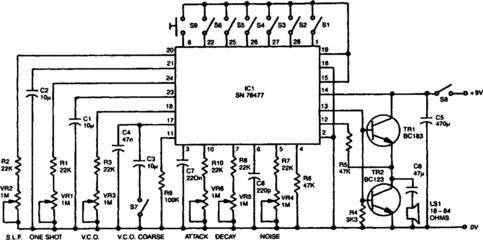
Six preset controls and seven selector switches enable a vast range of different sounds to be produced and altered at will. Such sounds as steam trains chuffing, helicopters flying, birds chirping, and machine guns firing are possible, as well as the usual police sirens, phaser guns, and bomb explosions. The circuit incorporates an amplifier giving 150-mW output into a small loudspeaker. Alternatively, a separate amplifier system can be used for disco effects, car alarms, etc. Continuous or one-shot sounds are possible. For one-shot sounds, a pushbutton switch is provided, which can also be used to turn continuous sounds on and off. A single IC, SN76477, provides all of the sound generation circuits.
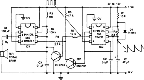
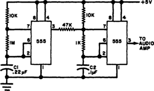
HEE-HAW SIREN
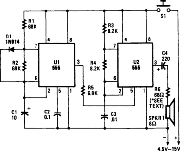
A pair of timer IC’s are the heart of a circuit that simulates the warbling hee-haw of a British police siren. One of the 555 timers, U2, is wired as an astable multivibrator operating at about 900 Hz. The other, U1, operates at approximately 1 Hz. Its output at pin 3 is a square wave with a 50% duty cycle—on and off cycles of about 0.5 second each. The output of U1 is applied to pin 5, the control-voltage terminal of U2. The frequency of the 555 timer IC is relatively independent of supply voltage, but can be varied over a fairly wide range by applying a variable voltage between pin 5 and ground. When U1’s output becomes high, U2 operates at about 800 kHz. That switching between two frequencies produces the warbling hee-haw signal.
PROGRAMMABLE-FREQUENCY ADJUSTABLE-RATE SIREN
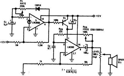
The LM380 operates as an astable oscillator with the frequency determined by R2/C2. Adding Q1 and driving its base, with the output of an LM3900 wired as a second astable oscillator, acts to gate the output of the LM380 on and off, at a rate fixed by R1/C1,
THE WAILING SIREN
Transistors Q1 and Q2, with feedback provided via C1 from the collector of Q1 to the base of Q2, forms a voltage-controlled oscillator (VCO). Depending on the voltage applied to Q2’s base, the VCO frequency ranges from around 60 Hz to 7.5 kHz. The instantaneous voltage applied to the base of Q2 is determined by the values of C2, R2, R3, and R4. When pushbutton switch S1 is closed, C2 charges fairly rapidly to the maximum supply voltage through R2, a 22-kΩ fixed resistor. That causes the siren sound to rise rapidly to its highest frequency. When the button is released, the capacitor discharges through R3 and R4 with a combined resistance of 124 kΩ, causing the siren sound to decay from a high-pitched wail to a low growl. If you want to experiment with the pitch of the sound at its highest frequency, try different values for C1. Increase its value for lower notes, and decrease it for higher ones. Different values for R2 will change the attack time. A 100-kΩ resistor provides equal attack and decay times. The way you handle the pushbutton varies the effect.
HIGH-POWER SIREN
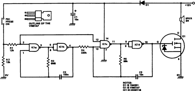
IC1a and IC1b are wired as a slow astable multivibrator and IC1c-IC1d are wired as a fast astable. Both are “gated” types, which can be turned on and off via PB1. The output of the slow astable modulates the frequency of the fast astable, and the output of the fast astable is fed to the external speaker via the Q1 VMOS power-FET amplifier stage.
HEE-HAW TWO-TONE SIREN
The circuit uses two gates of a 7400 IC, which is cross-connected to form an astable multivibrator driven by the 1-pulse per second output of the digital clock IC. The hee-haw circuit has a low-frequency astable modulator added to make a self-contained European-type siren. Tone and rate can be varied as desired by changing capacitor values. If the tone is too harsh, a simple R-C filter will remove the harmonic content—the multivibrator output is almost a square wave. With the resistor values shown, no start-up problems occur; but if the 2.2 or 2.7 kΩ resistors are changed too much, latch-up can be a problem.
SIREN SIMULATES STAR TREK RED ALERT
The signal starts at a low frequency, rises for about 1.15 seconds to a high frequency, ceases for about 0.35 seconds, then starts rising again from a low frequency, and so on, ad infinitum.
YELP OSCILLATOR
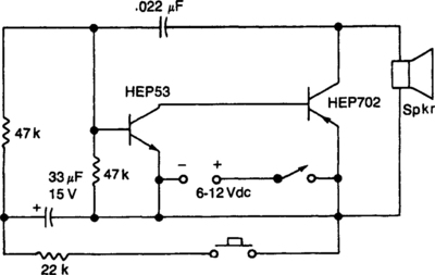
Close the pushbutton switch and the circuit starts the siren up-shifting to a higher frequency. Release it and the tone slides down until S2 is closed again. Tone quality is adjusted by changing the 0.022-µF capacitor.
ELECTRONIC SIREN
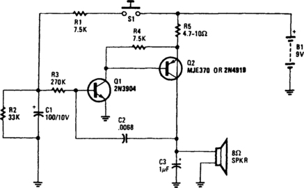
Fig. 7-17 Reprinted with permission from Radio-Electronics Magazine, December 1981. Copyright Gemsback Publications, Inc., 1981.
The wailing sound of a siren is generated by a VFO consisting of Q1 and Q2. Capacitor C2 provides the feedback for the oscillator. The frequency of the oscillator is varied by the voltage applied to the base of Q1 through R3. When switch S1 is closed, capacitor C1 charges, thus increasing the oscillator frequency. When S1 is released, capacitor C1 discharges, and the oscillator frequency decreases. Capacitor C3 limits the maximum oscillator frequency. The average battery current drain is about 15 mA.
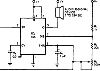
555 BEEP TRANSFORMER
The simple circuit transforms the steady beep of an audible-signal device, such as a Mallory sonalert, into a distinctive warble or chirp. The value of C2 determines just what tone color you’ll get. With the 1-μP value shown, the circuit produces a warble similar to the ring tone of an inexpensive phone. A 10-μP value produces a chirp similar to a truck’s back-up alarm. One elaboration of this circuit would be to use the second section of a 555 timer to drive a piezoelectric transducer instead of a sonalert; that modification would vary the tone’s pitch, as well as the chirp rate.
WARBLE-TONE ALARM
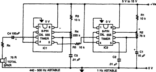
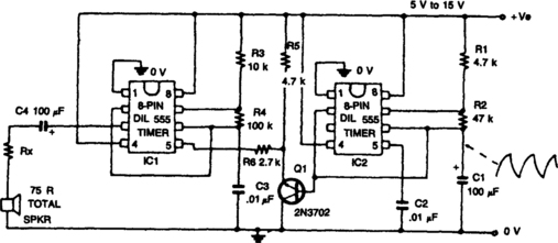
The circuit generates a warble-tone alarm signal that simulates the sound of a British police siren. IC1 is wired as an alarm generator and IC2 is wired as a 1-Hz astable multivibrator. The output of IC2 is used to frequency modulate IC1 via R5. The action is such that the output frequency of IC1 alternates symmetrically between 500 Hz and 440 Hz, taking one sound to complete each alternating cycle.
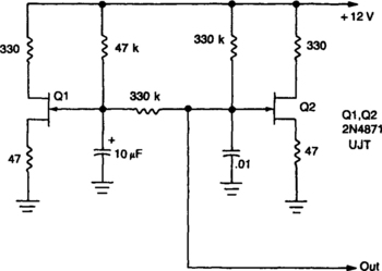
WARBLING TONE GENERATOR
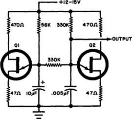
The circuit uses two unijunction transistors. The low-frequency sawtooth generated by Q1 modulates the high-frequency tone generated by Q2. The output should feed into a high-impedance amplifier. Q1 = Q2=2N4871.
WARBLE GENERATOR
The circuit uses a pair of 555 timers or a single dual timer. Capacitor C1 controls the speed of the warble, while C2 determines the pitch. The values shown should produce quite a distinctive signal.
WAILING ALARM
This circuit simulates the sound of an American police siren. IC2 is wired as a low frequency astable that has a cycling period of about 6 seconds. The slowly varying ramp waveform on C1 is fed to pnp emitter-follower Q1, and is then used to frequency modulate alarm generator IC1 via R6. IC1 has a natural center frequency of about 800 Hz. Circuit action is such that the alarm output signal starts at a low frequency, rises for 3 seconds to a high frequency, then falls over 3 seconds to a low frequency again, and so on, ad infinitum.
SIREN USES TTL GATES
The siren consists of two oscillator that generate the tones. A third oscillator is used to switch the others on and off alternately, giving the two-tone effect. By changing the capacitor values different tones can be produced.
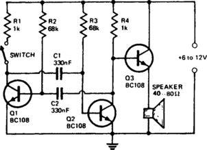
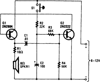
ELECTRONIC SHIP SIREN
The circuit consists of a multivibrator (Q1 & Q2), and a low-power output stage Q3. The speaker should have an impedance in the region of 40 to 80 ohms. To use a low-impedance speaker, connect an output transformer from the emitter of Q3 to ground. C1 and C2 determine the pitch of the siren and the values specified will provide a tone of about 300 Hz. Quiescent current is negligible. The output at the collector of Q2 can also be fed into an amplifier input via a 1-µF electrolytic, in series with a 12-kΩ resistor.