RF Oscillators
The sources of the following circuits are contained in the Sources section, which begins on page 173. The figure number contained in the box of each circuit correlates to the source entry in the Sources section.
5-MHz VFO
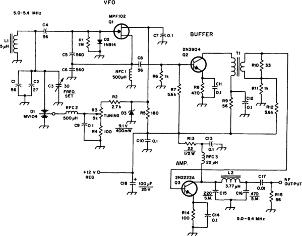
A JFET (Q1) serves as the oscillator. D2 helps to stabilize the transistor by limiting positive sine wave peaks and stabilizing the bias. Output from Q1 is supplied to a Class A buffer, Q2. It operates as a broadband amplifier by means of T1, which is untuned. Output amplifier Q3 is also a Class A stage. A low-pass, single-section filter is used at the output of Q3 to remove some of the harmonic currents generated within the system. The filter output impedance is 50 Ω. The injection level to the mixer is 600 mV p-p.
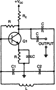
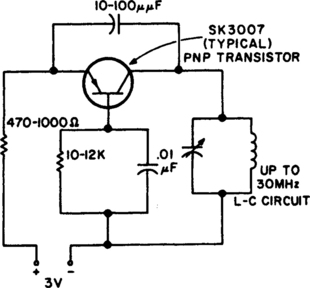
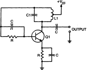
COLPITTS OSCILLATOR
When calculating its resonant frequency, use C1C2/C1 + C2 for the total capacitance of the L-C circuit.
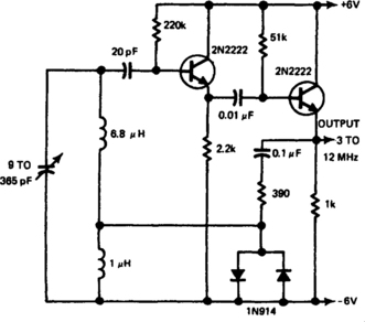
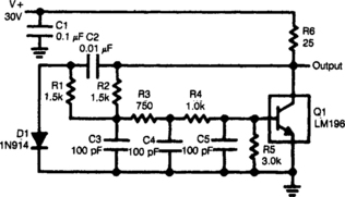
RF GENIE
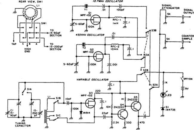
A variable oscillator covers 3.2 to 22 MHz in two bands—providing coverage of 80 through 15 meters plus most crystal-filter frequencies. Optional 455-kHz and 10.7-MHz crystal oscillators can be switched on-line for precise IF alignment. Generator output is on the order of 4 volts p-p into a 500-Ω load. A simple voltage-divider attenuator controls the generator’s output level, and a second output provides sufficient drive for an external frequency counter.
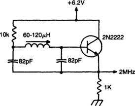
2-MHz OSCILLATOR
Miller 9055 miniature slugtuned coil; all resistors ¼W 5%; all caps min. 25 V ceramic.
LOW-DISTORTION OSCILLATOR
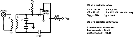
The 2N5485 JFET is capable of oscillating in a circuit where harmonic distortion is very low. The JFET local oscillator is excellent when a low harmonic content is required for a good mixer circuit.
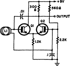
EMITTER-COUPLED BIG-LOOP OSCILLATOR
L1 is a loop of 10 to 20 turns of insulated wire with a diameter anywhere between 4” to 4’. This oscillator frequency (7 to 30 MHz) shifts substantially when a person comes near or into the loop. This oscillator together with a resonant detector might make a very good antipersonnel alarm. Transistors are 2N2926 or equivalent.