Audio Oscillators
The sources of the following circuits are contained in the Sources section, which begins on page 173. The figure number contained in the box of each circuit correlates to the source entry in the Sources section.
Wen-Bridge Sine-Wave Oscillator
Wien-Bridge Sine-Wave Oscillator
Easily Tuned Sine-/Square-Wave Oscillator
Simple Audio Sine-Wave Generator
Low-Cost Wien-Bridge Oscillator
Modified UJT Relaxation Oscillator
Wien-Bridge Oscillator Uses CMOS Chip
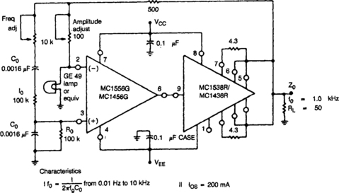
Adjustable Sine-Wave Audio Oscillator
Low-Distortion Thermally Stabilized Wien-Bridge Oscillator
Single-Supply Wien-Bridge Oscillator
Super-Low-Distortion Variable Sine-Wave Oscillator
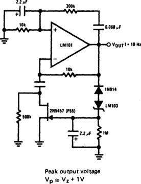
WIEN-BRIDGE SINE-WAVE OSCILLATOR
The 2N5457 JFET, as a voltage variable resistor in the amplifier feedback loop, produces a low distortion, constant amplitude sine wave getting the amplifier loop gain just right. The LM103 zener diode provides the voltage reference for the peak sine wave amplitude.
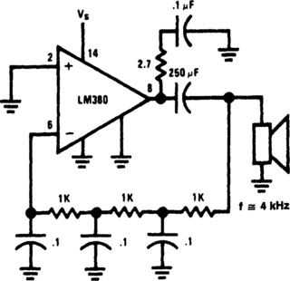
PHASE-SHIFT OSCILLATOR
Circuit uses a simple RC network to produce an exceptionally shrill tone from a miniature speaker. With the parts values shown, the circuit oscillates at a frequency of 3.6 kHz and drives a miniature 2½Π speaker at ear-piercing volume. The output waveform is a square wave with a width of 150 µs, sloping rise and fall times, and a peak-to-peak amplitude of 4.2 volts (when powered by 9 volts). Current drain of the oscillator is 90 mA at 9 volts, and total power dissipation at this voltage is 0.81 watt, which is well below the 1.25 watts the 14-pin version will absorb (at room temperature) before shutting down.
WIEN-BRIDGE OSCILLATOR
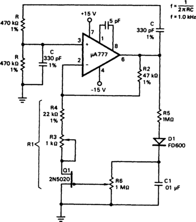
Field effect transistor, Q1, operates in the linear resistive region to provide automatic gain control. Because the attenuation of the RC network is one-third at the zero phase-shift oscillation frequency, the amplifier gain determined by resistor R2 and equivalent resistor R1 must be just equal to three to make up the unity-gain positive-feedback requirement needed for stable oscillation. Resistors R3 and R4 are set to approximately 1000 ohms less than the required R1 resistance. The FET dynamically provides the trimming resistance needed to make R1 one-half of the resistance of R2. The circuit composed of R5, D1, and C1 isolates, rectifies, and filters the output sine wave, converting it into a dc potential to control the gate of the FET. For the low drain-to-source voltages used, the FET provides a symmetrical linear resistance for a given gate-to-source voltage.
CODE-PRACTICE OSCILLATOR
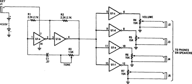
The inexpensive 7404 hex-inverter has enough amplification to handle a wide range of transducers. Closing the key completes the battery circuit and applies four to five volts to the 7404. Bias for the first two inverter amps (U1a and U1b) comes from the two resistors, R1 and R2, connected between their inputs and outputs. The capacitor and rheostat (R3/C1) close the feedback loop from the input to the properly phased output. The signal leaving U1b drives the remaining four inverter amplifiers, U1c through U1f; they, in turn, drive the phones or speakers. The volume control potentiometers, R4–R7, can have any value from 1500 to 10,000 ohms. The smaller values work best when speakers or low impedance phones, are used.
TONE ENCODER
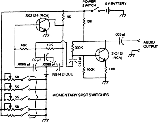
A basie twin-T circuit uses resistors for accurately setting the frequency of the output tones, selected by a pushbutton. Momentary switches produce a tone only when the button is depressed.
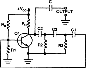
FEEDBACK OSCILLATOR
The circuit oscillates because the transistor shifts the phase of the signal 180° from the base to the collector. Each of the RC networks in the circuit is designed to shift the phase 60° at the frequency of oscillation for a total of 180°. The appropriate values of R and C for each network are found from ![]() ; that equation allows for the 60° phase shift required by the design.
; that equation allows for the 60° phase shift required by the design.
WIEN-BRIDGE OSCILLATOR
This Wien-bridge sine-wave oscillator, which uses two RCA CA3140 op amps covers 30 Hz to 100 kHz with less than 0.5 percent total harmonic distortion. The 10-kΩ pot is adjusted for the best waveform. Capacitor C1 and C2 is a two-gang, 450-pF variable with its frame isolated from ground. Maximum output into a 600-Ω load is about 1-volt rms.
PHASE-SHIFT OSCILLATOR
A single transistor makes a simple phase shift oscillator. The output is a sine wave with distortion of about 10%. The sine wave purity can be increased by putting a variable resistor (25 ohms) in the emitter lead of Q1 (x). The resistor is adjusted so the circuit is only just oscillating, then the sine wave is relatively pure. Operating frequency can be varied by putting a 10 kΩ variable resistor in series with R3, or by changing C1, C2, and C3. Making C1, C2, and C3 equal to 100 nF will halve the operating frequency. Operating frequency can also be voltage controlled by a FET in series with R3, or optically controlled by an LDR in series with R3.
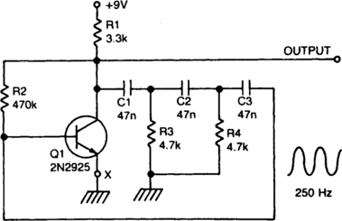
800-Hz OSCILLATOR
The following transistors can be used: HEP-254, O.C-2, SK-3004, AT-30H. To increase the frequency, decrease the value of the capacitors in the ladder network.
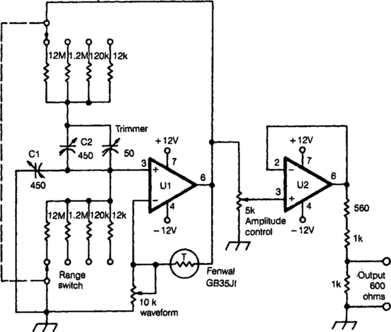
SINE-WAVE OSCILLATOR
The oscillator delivers a high-purity sinusoid with a stable frequency and amplitude.
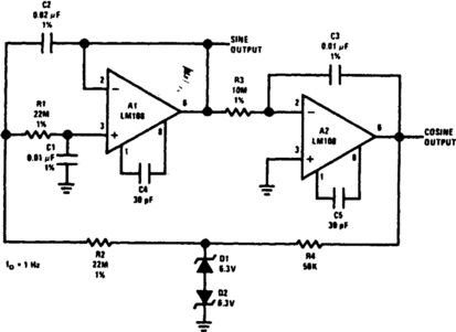
EASILY TUNED SINE-/SQUARE-WAVE OSCILLATOR
This circuit will provide both a sine- and square-wave output for frequencies from below 20 Hz to above 20 kHz. The frequency of oscillation is easily tuned by varying a single resistor.
VERY-LOW-FREQUENCY GENERATOR
This Wien-bridge oscillator generates frequencies of 1 Hz and 2 to 20 Hz in 2-Hz steps. Maximum output amplitude is 3-volts rms or 8.5 volts peak-to-peak. A pot-and-switch attenuator allows the output level to be set with a fair degree of precision to any value within a range of 5 decades.

ELECTRONIC BAGPIPE
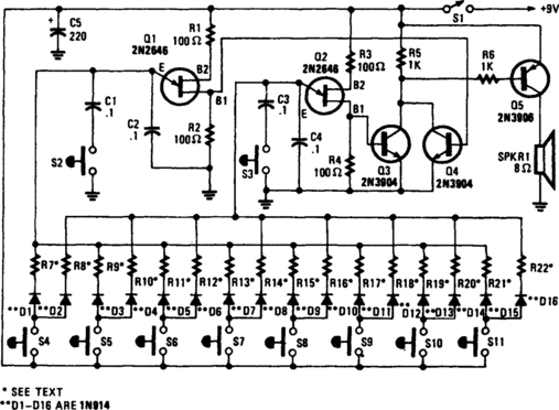
This circuit mimics the dual-tone drone sound that’s produced by the unusual wind instrument. Unijunction transistors Q1 and Q2 are connected in similar audio-oscillator circuits. Each of the oscillator frequencies is determined by one of the two resistors selected by one of the pushbutton switches, S4 through S11. The odd-numbered resistors in R7 to R21, determine the frequency for the Q1 oscillator circuit and the even-numbered resistors in R8 through R22, determine the frequency for Q2′s circuit.
When S4 is pressed, the positive supply is connected to both R7 and R8 through isolation diodes D1 and D2, causing both oscillators to operate. A narrow, fast-rising positive pulse is developed at B1 of both Q1 and Q2 for each cycle of operation. Transistors Q3 and Q4 serve as a simple audio mixer, which is used to combine the pulses from each oscillator. The mixed signal at the collectors of Q3 and Q4 is coupled through R6 to the base of Q5, which amplifies and drives an 8-0 speaker, SPKR1. Switches, S2 and S3 are used to reduce the oscillator’s frequency by about 50% when closed, to produce a new group of tones.
SIMPLE AUDIO SINE-WAVE GENERATOR
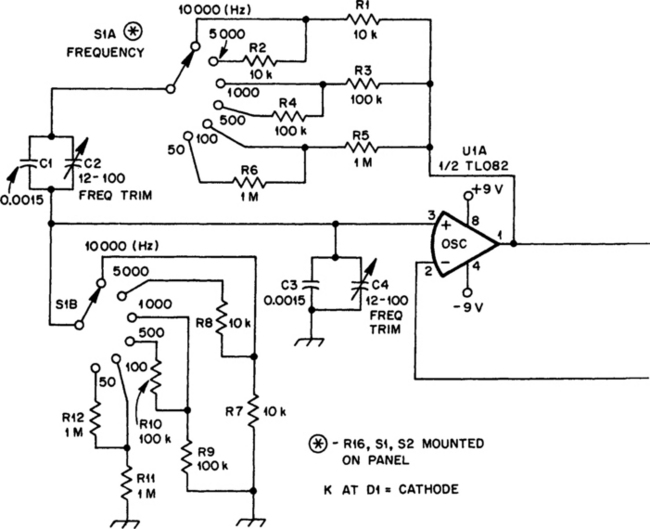
U1A, an op amp, oscillates at the frequency at which the phase shift in the Wien-bridge network is exactly zero degrees. Changing bridge component values changes the oscillator frequency. In this circuit, we need change only the two resistors to do this. S1A chooses a value among R1 through R6, and S1B similarly selects a value from R7 through R12. U1A must provide enough gain to overcome losses in the bridge, but not so much gain that oscillation builds up to the point of overload and distortion. U2 and C1 automatically regulate circuit gain to maintain oscillation. U2 places D1 across R13 with the proper polarity on both positive and negative alterations of the signal at pin 1 of U1. As the voltage at pin 1 of U1 approaches its peak value, D1 enters its Zener breakdown region, effectively shunting R13 with a resistive load. This shunting increases the amount of negative feedback around U1, reducing its gain. R15, Waveform Adj, allows you to optimize circuit operation for lowest distortion. U1B provides isolation between oscillator and load. With the values shown for R17 and R18, U1B operates at unity gain.
LOW-COST WIEN-BRIDGE OSCILLATOR
In the circuit, the frequency-trimming component is arranged so that the voltage across it is in quadrature with the voltage Vo from the bridge; as it is adjusted the attenuation of the bridge only changes a little, avoiding the need for a two-gang component. The range of variation of frequency is very limited. By using a high-gain amplifier and metal-film feedback resistors the loop gain can be set so that the unit just oscillates and the use of an automatic-gain-setting component (a thermistor, for example) is eliminated.
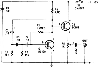
MODIFIED UJT RELAXATION OSCILLATOR
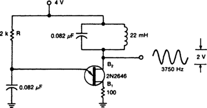
By placing a tuned circuit in the UJT oscillator’s current-pulse path, a 3750-Hz sinusoid can be created at B2 with the component values shown.
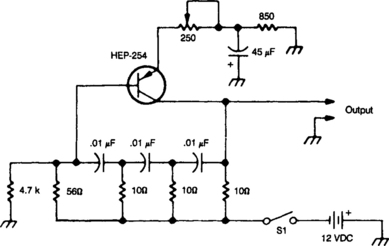
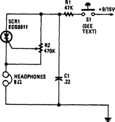
A 555 RC AUDIO OSCILLATOR
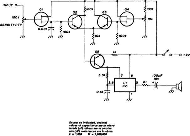
Transistor Q5 and the 1000-Ω resistor form the variable element that is needed for controlling the frequency of VCO by limiting the charging current flowing into the 0.15-µF timing capacitor according to the forward bias being applied to Q5. As the voltage on pins 2 and 6 of U1 reach ⅔ VCC (about 6 volts with a 9-volt supply) the timer will fire and pin 3 will be pulled low. Pin 7, an open collector output, goes low and begins to discharge the timing capacitor—through the 3.3-kΩ resistor. The discharge time provided by this resistor assures a reasonable, although asymmetrical, waveform for the aural signal generated by U1. At ⅓ VCC, the internal flip-flop resets, the output on pin 3 goes high, the open collector output on pin 7 floats, and the timing cycle begins again.
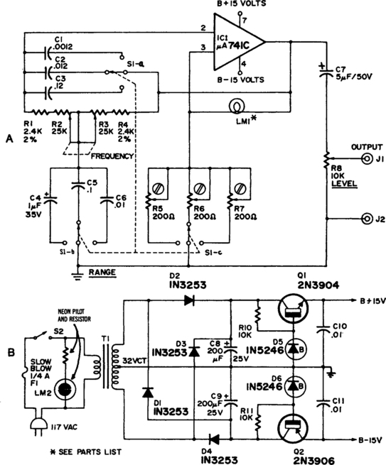
ADJUSTABLE SINE-WAVE AUDIO OSCILLATOR
Waveform purity at low frequencies for a Wien-bridge oscillator is enhanced by diode limiting. Lamp L1 stabilizes the loop gain at higher frequencies while the limiting action of R2, CR1, and CR2 prevents clipping at low frequencies and increases the frequency adjustment range from about 3:1 to greater than 10:1.
ONE-IC AUDIO GENERATOR
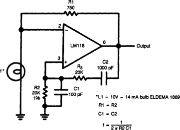
This high-quality low-cost generator covers 20 Hz to 20 kHz in three bands with less than 1% distortion. LM1–10 V, 14 mA (344, 1869, 914) or 10 V, 10 mA (913, 367).
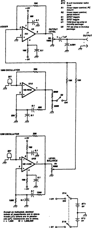
SIMPLE TWO-TONE GENERATOR
Two 741 operational amplifiers are used for the active elements in this Wien-bridge oscillator (the 1458 is the dual version of the 741), Frequencies of the two oscillators were chosen to fit standard component values. Other frequencies between 500 and 2000 Hz can be employed. They should not be harmonically related. The output level of U1A is set by a resistive divider, while the output of U1B is adjustable through R1. The output of the two oscillators is combined in U2, an op-amp adder with unity gain. The output from U2 can be adjusted using R2.
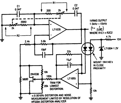
LOW-DISTORTION THERMALLY STABILIZED WIEN-BRIDGE OSCILLATOR
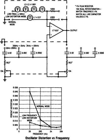
A variable Wien bridge provides frequency tuning from 20 Hz to 20 kHz. Gain control comes from the positive temperature coefficient of the lamp. When power is applied, the lamp is at a low resistance value, the gain is high, and oscillation amplitude builds. The lamp’s gain-regulating behavior is flat within 0.25 dB over the 20 Hz–20 kHz range of the circuit. Distortion is below 0.003%. At low frequencies, the thermal time constant of the small normal-mode lamp begins to introduce distortion levels about 0.01%. This is because of hunting when the oscillator’s frequency approaches the lamp’s thermal time constant. This effect can be eliminated, at the expense of reduced output amplitude and longer amplitude settling time, by switching to the low-frequency, low-distortion mode. The four large lamps give a longer thermal time constant, and distortion is reduced.
AUDIO OSCILLATOR
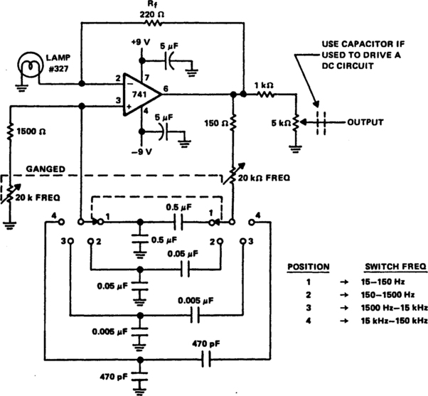
A Wen-bridge oscillator produces sine waves with very low distortion level. The Wien-bridge oscillator produces zero phase shift at only one frequency (f= ½πRC), which will be the oscillation frequency. Stable oscillation can occur only if the loop gain remains at unity at the oscillation frequency. The circuit achieves this control by using the positive temperature coefficient of a small lamp to regulate gain (Rf/RLAMP) as the oscillator attempts to vary its output. The oscillator shown here has four frequency bands covering about 15 Hz to 150 kHz. The frequency is continuously variable within each frequency range with ganged 20-kΩ potentiometers. The oscillator draws only about 4.0 mA from the 9-V batteries. Its output is from 4 to 5 V with a 10-kΩ load and the Rf (feedback resistor) is set at about 5% below the point of clipping. As shown, the center arm of the 5-kΩ output potentiometer is the output terminal. To couple the oscillator to a dc-type circuit, a capacitor should be inserted in series with the output lead.
AUDIO GENERATOR
This circuit produces a sinusoidal output of about 8 V pk-pk, which can be varied down to zero, at about 500 Hz. The signal is generated by a phase-shift oscillator.
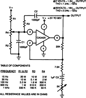
SINGLE-SUPPLY WIEN-BRIDGE OSCILLATOR
The adjustment of R4 contributes to the comparatively symmetrical output transfer characteristic of the CA3420 BiMOS op amp. To extend the lower operating frequency, remove C3 and use a dual supply.
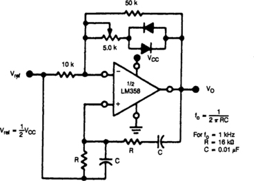
1-kHz OSCILLATOR
If fine output control is desired, add the 10-kΩ potentiometer. When the oscillator is connected to a dc circuit, then connect a dc-blocking capacitor in series with the potentiometer’s wiper arm.
INEXPENSIVE OSCILLATOR IS TEMPERATURE STABLE
The Colpitts sinusoidal oscillator provides stable output amplitude and frequency from 0°F to + 150°F. In addition, output amplitude is large and harmonic distortion is low: Oscillation is sustained by feedback from the collector tank circuit to the emitter. The oscillator’s frequency is determined by:
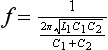
Potentiometer R3 is an output level control. Control R1 can be used to adjust base bias for maximum-amplitude output. The circuit was operated at 50 kHz with L1 = 10mH, C1 = 3500 pF, and C2 = 1500 pF.
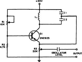
CODE-PRACTICE OSCILLATOR
Capacitor C1 charges through resistor R1, and when the gate level established by potentiometer R2 is high enough, the SCR is triggered. Current flows through the SCR and earphones, discharging C1. The anode voltage and current drop to a low level, so the SCR stops conducting and the cycle is repeated. Resistor R2 lets the gate potential across C1 be adjusted, which charges the frequency or tone. Use a pair of 8-Ω headphones. The telegraph key goes right into the B+ line, 9-V battery.
AUDIO OSCILLATOR
Fig. 1-34 Reprinted wtth permission of Radio-Electronics Magazine, August 1988. Copyright Gernaback Publlcationa, Inc., 1986.
The circuit’s frequency of oscillation is f=2.8/[C1 × (R1+R1)]. Using the values shown, the output frequency can be varied from 60 Hz to 20 kHz by rotating potentiometer R2.
A portion of IC1’s output voltage is fed to its noninverting input at pin 3. The voltage serves as a reference for capacitor C1, which is connected to the noninverting input at pin 2 of the IC. That capacitor continually charges and discharges around the reference voltage, and the result is a square-wave output. Capacitor C2 decouples the output.