This chapter covers the following Cisco-specified objective for the “Describe the operation of data networks,” and “Implement a small routed network” sections of the 640-822 ICND1 exam:
<objective>Determine the path between two hosts across a network
</objective> <objective>Describe basic routing concepts (including: packet forwarding, router lookup process)
</objective> <objective>Perform and verify routing configuration tasks for a static or default route given specific routing requirements
</objective> <objective>Verify network status and router operation using basic utilities (including: ping, traceroute, telnet, SSH, arp, ipconfig), SHOW & DEBUG commands
</objective> </feature><feature><title>Outline</title>320 | |||
320 | |||
322 | |||
323 | |||
324 | |||
325 | |||
326 | |||
327 | |||
328 | |||
329 | |||
330 | |||
331 | |||
332 | |||
333 | |||
336 | |||
338 | |||
340 | |||
340 | |||
341 | |||
341 | |||
342 | |||
343 | |||
345 | |||
346 | |||
347 | |||
347 | |||
348 | |||
348 | |||
351 | |||
351 | |||
353 | |||
Read the information presented in the chapter, paying special attention to tables, Notes, and Exam Alerts.
Because routing is a method of passing IP packets along to Layer 3 forwarding devices, take the perspective of the routing devices as it receives the packet and try to determine the information required to send it on to the next forwarding device.
Complete the Challenge and the Exercises at the end of the chapter. The exercises will solidify the concepts that you have learned in the previous sections.
This chapter involves several mathematical challenges that are based on the subnetting foundations learned in Chapter 5, “Implementing IP Addressing.” If necessary, review those concepts before tackling this chapter.
Complete the Exam Questions at the end of the chapter. They are designed to simulate the types of questions you will be asked on the CCNA, ICND1, and ICND2 exams.
So far, we have delved into many configurations of our routers that cover the administrative aspects of managing the device and providing basic connectivity. Don’t forget, however, that the routers were originally designed and created to do one main function. To give you a hint, the function is in its name.
Recall that Layer 3 is responsible for determining the best path to a network, using logical addressing such as IP addresses. This chapter discusses the fundamentals of how Layer 3 devices such as routers and Layer 3 switches develop the routing logic to determine where to forward IP packets to reach a destination network.
Objective:
Determine the path between two hosts across a network
To fully comprehend the routing of data, it helps to start where much of the data in a network originates: the computer. As application data is sent down the protocol stack, the source and destination IP addresses are added to the IP header. If the destination IP address is located on the same IP subnet as that on which the computer is, the computer adds the destination MAC address of that device at Layer 2 and sends it on the wire.
In instances where the destination IP address is on a remote network, it must send that traffic to a router on its segment that can forward the packet toward the destination network. Although you will forward traffic to this default gateway, the destination IP address remains unchanged. However, at Layer 2, the destination MAC address of the Ethernet frame reflects the default gateway’s MAC address because this is the forwarding device on the local data link segment.
In the example illustrated in Figure 10.1, the PC sends traffic to the server on the remote 10.1.34.0 network. The source IP address and MAC address are those matching the PC. On the other hand, the Layer 3 destination IP address of the IP packet reflects the IP address of the server (10.1.34.101). Because the destination IP address does not exist on the PC’s local subnet of 192.168.1.0, the PC encapsulates the router’s Fast Ethernet 0/0 MAC at Layer 2 because that is the configured default gateway for this segment. The switch in this scenario is operating as only a Layer 2 switch. Thus, despite having an IP address for management, this is not the default gateway for this segment because it is only forwarding frames at Layer 2.
Exam Alert
Despite having IP addresses assigned to switches for management purposes, Layer 2 switches do not act as the default gateway. If the exam does not mention the switch is Layer 2 or Layer 3, assume it is a Layer 2 switch.
When the router receives the frame addressed to its interface MAC, it processes the Layer 3 information and consults its routing logic to determine whether it knows where to route the packet. Because the destination network is attached to the router, it knows to send the packet out its Fast Ethernet 0/1 interface. A new Ethernet frame using its Fast Ethernet 0/1 MAC address (1243 523F A26C) for the source MAC address and the server’s MAC address (A345 764C F234) as the destination MAC are added to the original IP data as it is sent out to the destination segment.
Exam Alert
Be comfortable identifying what the source and destination IP address and MAC address should be at any point of the data delivery.
Objectives:
Verify network status and router operation using basic utilities (including: ping, traceroute, telnet, SSH, arp, ipconfig), SHOW & DEBUG commands
Suppose that in Figure 10.1 the traffic was a ping packet to test connectivity to the remote computer. If for some reason that ping failed, you would need to determine where the problem occurred. One method of testing the failure would be to make sure that you have connectivity to and from the originating PC and the default gateway.
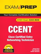
The default gateway on a computer can be assigned manually in the operating system or dynamically from a DHCP server. To ensure that the local computer has its IP and default gateway configured correctly, you need to look at the local PC’s configuration. This step differs depending on the operating system installed on the originating computer. Let’s assume for this example that the computer is using Windows as its operating system. You would need to go to a command prompt and enter ipconfig to see how the computer’s interface(s) are configured for IP. In Figure 10.2, you can see from the output on the computer that the computer has been dynamically assigned an IP address of 192.168.1.2 and a subnet mask of 255.255.255.0. Notice also that the default gateway is also configured correctly, pointing to the local router’s Fast Ethernet 0/0 IP address of 192.168.1.1.
To seal the troubleshooting deal, notice that we went so far as to verify that the computer has a correct IP-to-MAC address binding for the default gateway by issuing the arp -a command from the command prompt to display the computer’s ARP table. You can see from the output that the default gateway’s IP address of 192.168.1.1 does correspond to its Fast Ethernet 0/0 MAC address. This ARP entry will continue to remain in the computer’s volatile memory as long as it keeps getting used. If no packets are sent to this address for 5 minutes (default), the ARP entry is removed. If you want to manually clear your ARP table on your computer (useful in cases where you recently changed your default gateway), the command is arp-d followed by the IP address or a wildcard (*) to delete all ARP entries.
Seeing that the configuration of the originating PC is correct, next we should see if we have IP connectivity to the router’s Fast Ethernet interfaces. Because this is a small network, we can simply ping those IP addresses. In larger networks with many routers in between, it might be administratively easier to do a traceroute (the tracert command in Windows) to discover at what point along the routed path the ICMP packet fails.
So what happens if we can ping the two interfaces? At this point, we know that a packet can traverse our network, reach the default gateway, and exit the router’s remote network interface. The only culprit left is the remote PC. It is a pretty sure bet that the remote computer must have an interface problem or configuration error. Keep in mind that it too must return that packet to our network. Therefore, the remote computer must also have a default gateway configured so that it can return that packet to its remote network. Using the same steps as we used for the originating computer, we should be able to determine exactly what is causing this computer to not successfully return packets to our computer.
Objective:
Describe basic routing concepts (including: packet forwarding, router lookup process)
Routers are methodical, tactless devices in that they do not necessarily care about the individual IP addresses that exist on a subnet. Their sole obsession is to maintain their routing logic by keeping track of the networks that exist and which interfaces to use to send the traffic if an IP packet is destined for that network. By using routing devices to relay packets out of their interfaces to other forwarding devices or the destination network, the IP packet eventually reaches the destination.
At the heart of the routing logic for Layer 3 devices is the routing table. This table, located in volatile RAM, contains a mapping of all the best routes to networks that the router is aware of and the interfaces to exit to reach those networks. So how is the router aware of these networks? Generally, three routing sources can feed the routing table with this information:
Connected interfaces: As soon as you assign an IP address to a working (up/line protocol up) interface, the router associates the entire subnet of the interface’s IP address in the routing table.
Static routes: These are manual entries that an administrator enters into the configuration to specify the destination network and the next hop (router along the destination path).
Routing protocols: Protocols exchanged between routing devices to dynamically advertise networks.
Connected interfaces remain in the routing tables as long as the interface is active and has a valid IP address assigned to it. Static routes remain in the table as long as you do not remove the static route configuration and the next hop is valid (the interface to the next hop is up). Networks learned from dynamic routing protocols remain in the routing table as long as the next hop is valid and the routing devices do not stop hearing the network(s) being advertised from the neighbor routers.
Now that you are aware of the multiple sources of routing information, you must consider a feasible anomaly that could occur with your routing sources. Namely, if you have several sources of information such as connected interfaces, static routes, and multiple routing protocols, which one are you to trust when more than one source advertises the same network? For example, if a router learns about the 192.168.1.0/24 network from a routing protocol and a static route, how does the router decide which entry to place into its routing table?
The answer lies within a program logic in the IOS called the administrative distance. The administrative distances are values between 1 and 255 that are assigned to routing information sources. These values represent a level of trustworthiness of the information source, in which lower administrative distances are preferred over higher ones.
Note
The administrative distance applies only when multiple sources are advertising exactly the same subnet.
Table 10.1 lists the Cisco IOS default administrative distances for some of the routing sources.
It should come as no shock that connected interfaces are the most trustworthy sources because they are connected directly to the local router. Static routes have a low administrative distance of 1 because the Cisco IOS assumes that you are competent administrators and any manual entry of a routable network is trusted over any dynamic routing protocols such as EIGRP, OSPF, and RIP.
Objective:
Perform and verify routing configuration tasks for a static or default route given specific routing requirements
When you interconnect routers, as shown in Figure 10.3, they are aware of only their directly connected networks. Unless you configure a static route or use routing protocols, the routers will never know about their neighbors’ other networks, because they are not connected. In other words, Router A is unaware of Router B’s 172.17.0.0 network, and Router B is unaware of Router A’s 172.16.0.0 network.
So when do you use static routes as opposed to routing protocols? As mentioned before, static routes are manual configuration entries in which you tell the router how to get to destination networks that are not locally attached. This is useful in simple networks such as the one shown in Figure 10.3, in which there is a single link in or out of the networks, known as a stub network. Because there is only one link to get to the neighbor network, you don’t need to worry about reacting dynamically if the path fails because there are no alternate paths to that network. Additionally, if you want to have complete control of your routing path decisions or you want to conserve bandwidth on your links (routing protocols consume bandwidth), static routes can provide you authoritative control without requiring any link bandwidth or resources because they require only a local configuration.
Exam Alert
Keep in mind that static routes are used when you have a stub network, want control of your routing decisions, or want to conserve bandwidth on links.
The general idea behind the static route is to tell the router how to get to a destination network that is not attached to it by going through another router’s interface. It is similar to telling someone, “To go outside, go through that door.” The syntax to configure a static route in global configuration mode is ip route followed by the destination network, destination subnet mask, and the next-hop IP address of the neighbor’s interface. For example, to configure a route to the 10.0.0.0/8 network through the neighbor’s serial interface of 192.168.2.5, the command would look like this:
Router(config)# ip route 10.0.0.0 255.0.0.0 192.168.2.5Note
It is possible to specify the local interface instead of using a next-hop IP address on point-to-point links (a link with only two routers connected it on each side). On multi-access links such as Ethernet or Frame Relay, you should not use the interface because the local router does not know to which router to forward the information if multiple devices exist on the link.
In the stub network example shown in Figure 10.4, a static route to Router A and one to Router B were added, telling them about their neighbors’ Ethernet networks. These entries are placed in their routing tables, specifying any packets that are destined for those respective networks must go to the IP of the neighbor’s serial 0/0 interface. From that point, the packets are routed out Router A and Router B’s Ethernet interface because those destination networks are directly connected to the router. This entry remains in the routing table as long as the next-hop address remains valid (the serial network does not go down) or the configuration is not removed.
For several reasons such as security, processor resources, and routing path control, you can force the static route to remain in the routing table even if the next-hop interface goes down. This is easily achieved by adding the keyword permanent at the end of the ip route command.
At the end of an ip route static route command, it is possible to add a parameter to assign this particular static route a higher administrative distance than the default administrative distance of 1. These entries, known as floating static routes, are not placed in the routing table if the subnet is being advertised by a routing source with a lower administrative distance. Floating static routes are useful when you have a standby redundant link to another network that will activate in the event of a primary link failure.
For example, consider the example configured in Figure 10.5. Because you have redundant point-to-point links, you can configure the primary static route as usual and include a floating static route to be used if the primary link fails. The 2 at the end of the second static route identifies that route as the floating static route. This entry does not show up in the routing table because the primary route advertises the same subnet with a lower administrative distance (if not specified, the default is 1). If one of the serial 0/0 interfaces on the primary link goes down, the next hop is no longer valid and is removed from the routing table. Because the floating static route has the next lowest administrative distance, that entry is put in the routing table and that link is used until the primary link returns.
Objective:
Perform and verify routing configuration tasks for a static or default route given specific routing requirements
Static routes have proved their usefulness in situations where you want to add a network entry in a routing table when the network is reachable via a single path. This can turn into a daunting administrative task when there are a large number of networks in which you must configure static routes. This is especially true when you are connecting to your ISP because you do not want to configure a static route for every network on the Internet.
In these situations, you might be better served using something called a default route, as illustrated in Figure 10.6. This entry is a gateway of last resort for routers in that if a destination IP address does not have a network entry in the routing table, this route is used. The syntax for a default route is similar to a static route except that the destination and subnet mask are both 0.0.0.0:
Router(config)#ip route 0.0.0.0 0.0.0.0 192.168.1.10
Note
Again, you can specify the local interface as opposed to the next-hop IP address on a point-to-point link.
Exam Alert
Be sure to look closely at the wording in a question regarding a default route (gateway of last resort). When used in a router, the command is ip route 0.0.0.0 0.0.0.0; however, to configure a default route in a Layer 2 switch, it is ip default-gateway because Layer 2 switches do not have Layer 3 routing entries.
Note
In some situations a default route may appear dynamically in a routing table. Specifically, if you have configured your interface to dynamically be assigned an IP address and default gateway from a DHCP server using the ip address dhcp command, the router automatically places a default route in its routing table using the default gateway as the next hop.
Using the Security Device Manager web-based configuration interface, you can easily configure static and default routes with just a few clicks of the mouse. Specifically, from the Configure screen, select the Routing task to display routing configuration options. At the top of the screen shown in Figure 10.7 is a section dedicated to Static Routing. Here, when you click the Add button, a pop-up window displays the parameters that you can configure for static or default routes.
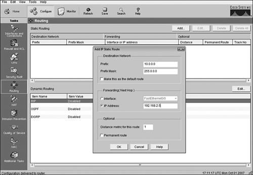
In the pop-up window, you specify the destination network and subnet mask, as you did for the IOS CLI command. The next hop defaults to a drop-down box that lists the interfaces, but you can select the IP Address option and specify the next-hop address. Also notice that there is a checkbox to make this route a default route, as well as a checkbox to make this a permanent static route entry. If you wanted to make this route a floating route, you could also put the distance metric for this route to an administrative distance value other than 1. After you click the OK button, the route is added to the running configuration of the IOS.
The best way to verify a static or default route configuration is by checking that the route is evident in the routing table. The command to view the IP routing table is show ip route. If you want to see the routing entry for a specific network, you can append that subnet to the show ip route command (for example, show ip route 192.168.23.0). The following example displays the output of the show ip route command:
Router> show ip route
Codes: C - connected, S - static, I - IGRP, R - RIP, M - mobile, B - BGP
       D - EIGRP, EX - EIGRP external, O - OSPF, IA - OSPF inter area
       N1 - OSPF NSSA external type 1, N2 - OSPF NSSA external type 2
       E1 - OSPF external type 1, E2 - OSPF external type 2, E - EGP
       i - IS-IS, L1 - IS-IS level-1, L2 - IS-IS level-2, * - candidate default
       U - per-user static route, o - ODR, P - periodic downloaded static route
       T - traffic engineered route

Gateway of last resort is not set

S    172.17.0.0/16 [1/0] via 192.168.1.10
C    172.16.0.0/16 is directly connected, FastEthernet0/0
     192.168.1.0/30 is subnetted, 1 subnets
C       192.168.1.8 is directly connected, Serial0/0/0
S*   0.0.0.0/0 [1/0] via 192.168.1.10
Notice that the beginning of the output has a legend identifying the possible codes that can be listed in the routing table. In the table itself, you can see the two directly connected networks signified by the letter C. In addition, you can also see the static route to 172.17.0.0 and the static default route entries (indicated by the letter S), using 192.168.1.10 as the next hop. Also notice that the routing table identifies that the gateway of last resort (192.168.1.10) is set on this router because a default route was configured with the next hop to that address.
Note
You can clear out an entry in your routing table by using the clear command followed by the network or * for all networks in privileged EXEC mode. For example, to clear the 192.168.1.0 network from your routing table, you would enter the following:
Router# clear ip route 192.168.1.0When complex networks contain multiple interconnections, static routes are no longer a practical solution because they cannot adapt or react to changes in the topology. Not to mention, the configuration complexity can grow exponentially as you add more devices to the network.
Exam Alert
Do not confuse routing protocols with routed protocols on the exam. Routed protocols are protocols such as those in the IP protocol suite that are used to carry the data across our network. Routing protocols are exchanged between routing devices to determine the optimal path to route the routed protocols.
For example, given the network design in shown Figure 10.8, Router A knows only the three directly connected networks attached to the router. For IP packets to reach the 172.17.0.0 network via static routes, you would have to configure Router A to go through one of its neighbor routers, such as Router B. However, Router B also requires a static route to 172.17.0.0 because that network is not directly connected to it. Supposing that the router is using Router F as its next hop, that router does not require a static route because it is directly connected. Unfortunately, our configuration undertaking does not stop there because we have to configure a static route in Router F and Router B back to the 172.16.0.0 network.
Granted, the configuration scenario shown in Figure 10.8 is not drastically difficult or strenuous, but imagine if the network contained 20 more routers. More importantly, consider what would happen if the link between A and B went down. Because the routes are statically configured in the routers, you must now go back and remove the static routes in Routers A and B and redirect the traffic by configuring static routes to go through Routers C, D, and E. Not to mention, you must remove and reconfigure static routes back to the 172.16.0.0 network in Routers F, E, D, and C.
To alleviate the administrative calamity you might have to encounter with static routes in complex networks, you can use dynamic routing protocols. If you configure routing protocols, the routers advertise their connected networks to the rest of the routers in the network, thus minimizing the amount of configuration required. In addition, routing protocols can detect and adapt to topology changes in the internetwork.
Because one of the core responsibilities of routing protocols is to build routing tables to determine optimal routing paths, you need to have some means of measuring which routes are preferred when there are multiple pathways to a destination. Routing protocols use some measure of metrics to identify which routes are optimal to reach a destination network. The lowest cumulative metric to a destination is the preferred path and the one that ultimately enters the routing table. Different routing protocols use one or several of the following metrics to calculate the best path:
Hop count: The number of routing devices that the packet must travel to reach a destination network.
Bandwidth: The cumulative bandwidth of the links to the destination in kilobits per second.
Delay: The length of time (measured in microseconds) a packet takes from source to destination.
Reliability: The consistency of the links and paths toward the destination based on error rates of the interfaces.
Load: The cumulative amount of congestion or saturation of the links toward the destination.
MTU: The maximum frame size that is allowed to traverse the links to the destination.
Cost: An arbitrary number typically based on the bandwidth of the link.
As you will see in the following sections, routing protocols are categorized into several different classifications based on common characteristics and properties that they share. The first of these classifications revolves around the contents of routing updates that Layer 3 devices advertise to their neighbors. Specifically, if the routing updates do not contain the subnet mask along with their respective advertised networks, they are said to be classful routing protocols. Conversely, if the subnet mask is transmitted along with the network information, it is characterized as a classless routing protocol. This may seem like a trivial characteristic to define routing protocols, but as you will see, the results of the subnet mask being present or not in routing updates can affect the routing protocols you choose and how efficiently you can design your entire network.
With classful routing protocols, you assume that your network’s design conforms to the class boundaries of IP subnets. In other words, major networks in your design use their default classful subnet masks as described in Chapter 5, “Implementing IP Addressing” (for example, Class A uses 255.0.0.0, Class B uses 255.255.0.0, and Class C uses 255.255.255.0). If you happen to subnet a major network into smaller subnets, classful routing protocols are disadvantageous, because they do not receive the revised subnet mask. For this reason, classful routing protocols process updates in one of two ways:
If the network in the updates matches the same major classful network on the interface through which it was received, it uses the subnet mask of the interface and places it in the routing table.
If the router advertises a network to a different major network out an interface that is not in the same major network, it automatically summarizes the network to its classful boundary.
For example, when Router B in Figure 10.9 sends an update to Router A using a classful routing protocol (RIPv1 in this example), it summarizes the 172.17.30.0/24 to a default Class B 172.17.0.0 network because it is going out the serial 0/0 interface, which does not contain a subnet in that major network. The 192.168.1.60 network, on the other hand, is in the same major network, so it does not automatically summarize that subnet. When Router A receives that update, it adds the 172.17.0.0 network to its routing table, specifying Router B’s serial interface IP (192.168.1.10) as the next hop to reach that network. In addition, it adds the 192.168.1.60 network as well, using its interface mask because it is in that same major network.
Now consider if the Ethernet segment of Router B’s 192.168.1.60 network had a /29 subnet mask. The end result would still be the same as before in that Router B would advertise the 192.168.1.60 subnet and Router A would use its interface’s subnet mask of /30. In these instances, classful routing protocols are not the optimal choice because Router A has a route to only a third of the 192.168.1.60 /29 subnet. For this reason, when you subnet a major network, you must be sure that you use the same subnet mask throughout your network design with classful routing protocols. This same subnet design is commonly referred to as a Fixed-Length Subnet Mask (FLSM) network design.
Classful routing protocols can also be problematic when major classful networks are subnetted and are haphazardly dispersed throughout the network, as illustrated in Figure 10.10. When Routers A and C summarize their networks to Router B, Router B thinks that the 172.16.0.0 network is out both of its serial interfaces. This could easily result in traffic destined for 172.16.10.0 and 172.16.50.0 being load balanced out each interface, resulting in 50% packet loss because the packets are sent in a round robin fashion between both interfaces.
Exam Alert
Be sure to know that classful routing protocols support automatic summarization and must have a FLSM network design without any discontiguous networks.
Because classless routing protocols advertise the subnet masks in their routing updates, discontiguous networks are no longer an issue because routing devices are aware of the subnetted networks. In addition, the requirement of using the same subnet mask throughout the network ceases to apply because the routers do not automatically summarize the networks to a classful boundary. No longer inhibited by these constraints, you are free to use different subnet masks, known as Variable-Length Subnet Masks (VLSMs) in your network design. In addition, you now have full autonomy to manually summarize networks as you wish to help keep routing tables small to conserve resources. VLSM and route summarization are described in greater detail in the following sections.
Using classless routing protocols affords you the luxury of having support for a VLSM network design. This is advantageous in your network planning because you can allot the appropriate number of IP addresses required for each link. Not to mention, by assigning the minimal number of IP addresses required for a given link, you conserve IP addresses. For example, you can use a /30 subnet mask for point-to-point links because you need only two available IP addresses and a /27 subnet mask on an Ethernet segment to accommodate 30 hosts. If you were using classless routing protocols, you would have to use a /27 for all links, which would inevitably waste 28 IP addresses on the point-to-point links.
Exam Alert
Remember that point-to-point links require only a /30 (255.255.255.252) subnet mask because you need only two usable IP addresses for the router’s interfaces on each side of the link.
Throughout your certification and career, it is quite possible you will have to design your network given a usable subnet and host requirements for all your links. When tackling this designing task, be sure to adhere to the following guidelines:
If possible, start with the larger subnets first.
Write out the ranges that you have assigned to ensure that you do not accidentally overlap subnets.
Make sure your networks start on incremental boundaries (128, 64, 32, and so on).
Exam Alert
Be prepared to use VLSM to assign subnets to links given the subnettable network and host requirements.
Challenge
Given the design shown in Figure 10.11, determine how you can use VLSM to ensure that you are using the appropriate subnets given a design scenario. In this example, the zero subnets are available for use.
|
As already mentioned, classful routing protocols automatically summarize advertised networks to the classful subnet boundaries. Classless routing protocols, on the other hand, require you to manually control the networks being summarized to your neighbors in the router configuration. By aggregating a contiguous set of networks into an advertised summarized route, you keep the size of the routing tables to a minimum. Neighbors that receive the summarized route do not need to know about the individual subnets you create behind your router because they inevitably have to go through your router to get to them. The additional offshoot of this summarized picture is that your classless routing protocols do not need to notify those neighbors if one of those subnets goes down because they do not even have that subnet in their routing tables. Thus, you can isolate topology changes to be contained behind that summarizing router.
Because you are required to manually specify the networks you are to advertise, you must learn how to accurately summarize smaller subnets into one or several larger networks, or supernets. The rules for supernetting are similar to subnetting, except in this case, you are stealing bits from the network portion of an IP network to create a larger network. The rules for supernetting are as follows:
Be sure that the networks are contiguous (otherwise, you would be summarizing networks that you do not have behind the router).
Count the number of networks you want to summarize.
Determine an increment that is equal to or less than the number of networks.
Make sure your base networks start on incremental boundaries (128, 64, 32, and so on) for the number of networks you are summarizing.
Calculate the subnet mask by the number of bits you need to steal from the original subnet to equal that incremental value.
The beauty of supernetting is that the resultant network and subnet mask will designate many IP address networks in a single entry. The fact that you are stealing bits from the network portion of an IP address could quite easily violate the traditional barriers of classful addressing, known as Classless Interdomain Routing (CIDR).
For instance, it would not be uncommon to see a summary entry look like the following: 192.168.16.0 /20. This single entry used to be a Class C (/24), but four bits were stolen from the network portion to represent 16 networks (24 = 16). When you advertise this supernet to neighbors, they know that they must go through your router to get to networks 192.168.16.0 through 192.168.31.0 (16 total networks).
Exam Alert
Be prepared to determine the networks being advertised in a given supernet or determine the summary network, given the networks to be summarized.
Figure 10.12 illustrates a typical route summarization example in which Router B is summarizing all its subnetted networks to Router A as one supernetted network. Following the steps outlined previously, you can determine the aggregate network entry to advertise, as follows:
The networks are all contiguous, so you can summarize them accurately.
A total of 32 networks need to be summarized.
32 conveniently falls on an incremental boundary.
Because the network is 192.168.64.0, 64 is an increment of 32 so we can use that as the base network for the summary route.
You must steal 5 bits (25 = 32) from the /24 network, so /19 (24 – 5 = 19).
By creating the summary route 192.168.64.0 /19, Router A is required to maintain only that one entry in its routing table as opposed to the individual 32 subnets. If a topology change occurs in one of the subnets behind Router B, there is no need to advertise that change to Router A because it knows about only the summarized network.
Routing protocols can fall under two major categories depending on the autonomy of the network on which the routing protocol exists. The identifying characteristic of the category to which the routing protocol belongs ultimately depends on whether the routing protocols exchanges updates within a network that is under your administrative control. When the network is under your control in your own administrative domain, it is known as an autonomous system. Routing protocols used to disseminate information to maintain routing tables and establish pathways inside an autonomous system are categorized as Interior Gateway Protocols (IGPs).
Conversely, the other category of routing protocols is designed to route in between these autonomous systems. For instance, Border Gateway Protocol (BGP) is a routing protocol that is used by ISPs for routing traffic over the Internet. Because the Internet comprises thousands of networks, each under different administrative control, you need to use an Exterior Gateway Protocol such as BGP to route in between these autonomous systems.
In addition to being an IGP/EGP or classful/classless, routing protocols can also fall into one of three classes. Again, the functionality and characteristics of the routing protocol dictate under which class it falls. The most long-standing of these classes is distance vector routing protocols.
Distance vector routing protocols concern themselves with the direction (vector) in which the destination lies and some means of measurement (metric) it takes to reach that destination. Distance vector routing protocols inform their directly connected neighbors of all the connected and learned networks they know about in their routing tables. In fact, they broadcast the contents of the entire routing table to their neighbors periodically, regardless of whether there is a change in the network topology. When the neighbors receive that routing information, they identify and add any new networks to their routing tables and update the metric before eventually passing it on to their neighbors. Because the routing table information is updated before it is sent on to neighbors, downstream routers do not learn that information first hand. For this reason, distance vector routing protocol update processing is often referred to as “routing by rumor.” Distance vector routing protocols are discussed in greater detail in Chapter 11, “Distance Vector Routing Protocols.”
As the name states, link-state routing protocols advertise the state of the links in the network. In fact, they advertise the states and metrics (cost) of all the links they know about for the entire topology to their neighbors, as opposed to just the best routes in your routing table. This detailed overview of the entire routing domain enables each router to calculate and make a decision on the best route from this first-hand information, rather than listen to what its neighbor believes is the best route. In fact, link-state routing protocols keep three tables: a neighbor table of all discovered neighbors, a topology table of all the possible routes to reachable networks learned, and a routing table that contains the best route based on the lowest metric calculated from the topology table.
At first, this may sound like a lot of information to be exchanged between routers; however, link-state routing protocols initially discover their neighbors when they first boot up and synchronize their topology tables. After the neighbor discovery and topology synchronization, they send only periodic hello messages to let their neighbors know they are still functioning. This is significantly different from distance vector routing protocols that periodically exchange the entire routing table, which can contain a large amount of information, depending on the size of the network.
In addition, link-state routing protocols react much faster when a topology change occurs in the network. In fact, these protocols were initially created in response to the slow convergence issues that you typically encounter with distance vector routing protocols. The downfall to these routing protocols is the resources they consume in the router. Namely, maintaining and processing three tables consume quite a bit of memory and processor power.
They say it usually takes three tries to get something absolutely right. The truth behind this saying is that you learn from the mistakes of the previous two attempts. Such is the case with advanced distance vector, often referred to as hybrid or balanced hybrid routing protocols. Because they take the best features and avoid the pitfalls of both distance vector and link-state routing protocols, hybrid routing protocols are a more proficient breed of routing protocols than their predecessors.
Now that you have learned about the several types of routing sources, including static routes and dynamic routing protocols, it’s time to revisit the routing table and solidify how network entries are added and used in routing decisions. To help illustrate this process, refer to the following show ip route output:
RouterA> show ip route
Codes: C - connected, S - static, I - IGRP, R - RIP, M - mobile, B - BGP
       D - EIGRP, EX - EIGRP external, O - OSPF, IA - OSPF inter area
       N1 - OSPF NSSA external type 1, N2 - OSPF NSSA external type 2
       E1 - OSPF external type 1, E2 - OSPF external type 2, E - EGP
       i - IS-IS, L1 - IS-IS level-1, L2 - IS-IS level-2, * - candidate default
       U - per-user static route, o - ODR, P - periodic downloaded static route
       T - traffic engineered route

Gateway of last resort is not set

R    172.17.0.0/16 [120/1] via 192.168.1.10, Serial0/0/0
C    172.16.0.0/16 is directly connected, FastEthernet0/0
     10.0.0.0/8 is variably subnetted, 4 subnets, 3 masks
D       10.2.0.0/16 [90/2297856] via 192.168.1.10, Serial0/0/0
D       10.3.0.0/16 [90/2297856] via 192.168.1.10, Serial0/0/0
R       10.0.0.0/8 [120/2] via 192.168.1.6, Serial0/0/1
D       10.1.0.0/16 [90/2297856] via 192.168.1.10, Serial0/0/0
D       10.4.0.0/16 [90/2297856] via 192.168.1.10, Serial0/0/0
O       10.4.0.1/32 [110/65] via 172.16.0.1, FastEthernet0/0
     192.168.1.0/30 is subnetted, 2 subnets
C       192.168.1.8 is directly connected, Serial 0/0/0
C       192.168.1.4 is directly connected, Serial 0/0/1
Notice that there are now several entries for directly connected networks, a static route, and several dynamic routing protocol entries from EIGRP, RIP, and OSPF. For each dynamic routing protocol, the network and subnet mask are being advertised by neighbor routers, followed by two numbers in brackets separated by a slash (/). The number to the left of the forward slash is the administrative distance of the routing protocol. The number to the right of the forward slash represents the metric that is being used by the routing protocol to determine the best path to the destination network. This information is immediately followed by the router from which it learned this information (thus, the next-hop address). The last item in the routing entry represents the interface packets must exit to reach those networks.
Assuming that several of the routing protocols advertised the same networks, how did these specific network entries come to be in the routing table? The obvious answer is that the interfaces, a static route, and multiple routing protocols were configured and the resultant table just appeared. However, to answer the question more specifically, each routing protocol determined which routes should be entered in the routing table based on the lowest metric to those destinations. In the chance that one or more routing sources is trying to place a network entry in the routing table for exactly the same subnet, the routing protocol with the lowest administrative distance is chosen because it is the most trustworthy.
After the routing table is built, packets are routed to their destinations by examination of the destination IP address in an IP packet and associating the network in the routing table with that IP address. If there isn’t a match for the network lookup, the packet is forwarded to its default route. If the gateway of last resort is not set (as in this show ip route output), the packet is dropped, and an ICMP destination unreachable message is sent back to the source to indicate that the destination cannot be reached.
Exam Alert
Routing of packets is based on the destination IP address in a packet. If the router does not have an entry for the packet’s associated network or does not have a default route, it sends an ICMP destination unreachable message back to the source.
In the show ip route output, several entries for the 10.0.0.0 network are listed in the routing table. Interestingly, there is a RIP entry for the 10.0.0.0 /8 network to go out serial 0/0/1 and four EIGRP-learned networks for 10.1.0.0 /16, 10.2.0.0 /16, 10.3.0.0 /16, and 10.4.0.0 /16, all destined for interface serial 0/0/0. Because the EIGRP networks are subnets of the major 10.0.0.0 network, which interface will the router use to route a packet destined, for example, for 10.1.0.3?
Cisco’s routing logic answers this question by using a rule called the longest match. The longest match rule states that when a packet has multiple possible network entries to use, the more specific subnet is used over the less specific. In other words, the longer the number of bits in the subnet mask (thus the smaller subnet), the more chance it has of being the chosen network. In the routing table example, a packet destined for 10.1.0.3 would use the subnet with the longest prefix (subnet mask), which is the EIGRP route for 10.1.0.0/16 exiting interface Serial 0/0/0.
You are likely to encounter in your Cisco travels certain situations in which you must run multiple routing protocols in your network. For instance, your company is in the process of merging with another company’s network, and their routers are running a different routing protocol than yours. In addition, you may have to connect your Cisco router network to a non-Cisco routing infrastructure and you are using Cisco proprietary routing protocols.
In instances where you are running multiple routing protocols, it may be necessary to have networks advertised in one routing protocol injected into the other. Unfortunately, because routing protocols are so diverse in nature, they do not inherently interact or exchange information with each other when multiple routing protocols are running in the network. The transferal of network information from one routing protocol into another is a manual configuration called redistribution.
The redistribution configuration is typically done at one or a couple of routers that sit on the boundary between each routing protocol, as illustrated in Figure 10.13. These devices run both routing protocols and must be manually configured to inject the networks learned from one routing protocol into the next. Redistribution can occur in one of two fashions:
One-way redistribution: Networks from an edge protocol are injected into a more robust core routing protocol, but not the other way around. This method is the safest way to perform redistribution.
Two-way redistribution: Networks from each routing protocol are injected into the other. This is the least preferred method because it is possible that suboptimal routing or routing loops may occur because of the network design or the difference in convergence times when a topology change occurs. Figure 10.13 is an example of two-way redistribution.
This chapter looked more closely at the operations involved in routing packets with Layer 3 devices such as routers and Layer 3 switches. You send packets from workstations on the local network to routing devices by configuring those devices with a default gateway IP address that matches the IP of your router. When the packet arrives at the router, it consults its routing table to determine whether the destination IP address in the IP packet has a match for the destination’s network. If it does not have a matching entry, it looks to see whether the routing table has a default route. If no gateway of last resort is set, it drops the packet and sends an ICMP destination unreachable message back to the source. In instances where there are several matches for the destination network, it uses the entry that has the longest match.
The entries in the routing table can come from several routing sources. When the interface is operational and an IP address is assigned, they show up in the routing table as connected interfaces. Manual static route entries that were manually configured show up as an S. Routing protocols choose their best network paths by calculating the lowest metric for their respective routing protocols. If multiple routing sources advertise the same subnet, the source with the lowest administrative distance is placed in the routing table.
The routing protocols can fall into several categories, based on the characteristics that the protocols utilize. For instance, if a routing protocol does not advertise the subnet mask in its routing updates, it is a classful routing protocol. Classful routing protocols require the network design to have the same subnet mask in the design known as FLSM. In addition, these routing protocols cannot support discontiguous networks and automatically summarize network entries to the classful boundary when crossing interfaces in other major networks. When subnet masks include the routing advertisements, these updates are said to be classless. Classless routing protocols support VLSM network designs, discontiguous networks, and require manual summarization of networks.
If the routing protocol is designed to route inside an autonomous system, that routing protocol is an IGP. EGP routing protocols, on the other hand, are designed to route between autonomous systems.
Finally, routing protocols can belong to one of the following three classifications:
Distance vector: The entire routing table is periodically sent to directly connected neighbors regardless of a topology change. These routing protocols manipulate the routing table updates before sending that information to their neighbors and are slow to converge when a topology change occurs.
Link-state: All possible link states are stored in an independent topology table in which the best routes are calculated and put into the routing table. The topology table is initially synchronized with discovered neighbors followed by frequent hello messages. These routing protocols are faster to converge than distance vector routing protocols.
Hybrid: By using the best characteristics from both link-state and routing protocols, these advanced routing protocols efficiently and quickly build their routing information and converge when topology changes occur.
This exercise tests your configuration skills in configuring a static and default route.
Estimated Time: 5 minutes
Enter privileged EXEC mode.
Enter global configuration mode.
Configure a static route for the 10.23.5.0/24 network using 192.168.64.2 as the next-hop address.
Configure a floating static route for the 10.23.5.0/24 network using 192.168.60.3.
Configure a default route to exit out of your serial interface.
This exercise ensures that you can accurately supernet smaller subnets into one summary route.
Estimated Time: 5 minutes
Given the following networks, what is the summary route you can use to advertise these individual subnets to your neighbor router as an aggregate entry?
172.16.0.0 /16
172.17.0.0 /16
172.18.0.0 /16
172.19.0.0 /16
Count the number of networks you want to summarize.
Determine an increment that is equal to or less than the number of networks.
Make sure your base networks start on incremental boundaries (128, 64, 32, and so on) for the number of networks you are summarizing.
Calculate the subnet mask by the number of bits you need to steal from the original subnet to equal that incremental value.
When a packet is destined for a remote network, the Layer 3 source address is the workstation or device that is sending the traffic. The destination Layer 3 address is the IP address of the destination device. At Layer 2, the source address is the MAC address of the sending workstation or device. The destination Layer 2 address, however, is the MAC address of the default gateway. The default gateway is the routing device on the local segment that is responsible for forwarding packets from the local segment to remote networks. | |
Static routes are used primarily in stub networks or when the administrator wishes to have complete control over the routing decisions of their routing devices. Routing protocols are used in complex networks with multiple paths to a destination. Unlike static routes, routing protocols can dynamically react to topology changes in the internetwork. | |
Distance vector routing protocols periodically send routing table updates to their directly connected neighbors regardless of whether there is a change in the topology. These routine routing updates contain the contents of the entire routing table. | |
Link-state routing protocols initially discover their neighbors and retain that information in a neighbor table. Information about all possible routes is exchanged between these neighbors and stored in a router’s topology table. After the initial exchange of information, link-state routers periodically send hello messages as opposed to full routing updates. With the knowledge of all possible routes in the topology, the routers calculate the best route to each destination and place them in the routing table. | |
Classful routing protocols do not contain the subnet mask in the routing updates. Networks using classful routing protocols require that a FLSM design does not support discontiguous networks. Classless routing protocols updates contain the subnet mask that enables the network design to support VLSM and discontiguous networks. |
D. A packet destined for 192.168.1.34 /24 would require a network entry for 192.168.1.0 in the routing table. Because there isn’t an exact match for that network, the router sends it out the interface specified in a default route. This router does not have a default route configured, so the packet is dropped, and an ICMP destination unreachable is sent to the source. Answer A is incorrect because packets destined for the 10.0.0.0 /8 exit the serial 0/1 interface. Answer B is incorrect because packets destined for the 172.17.0.0 /16 exit the serial 0/0 interface. Answer C is incorrect because packets destined for the 172.16.0.0 /16 exit the Fast Ethernet 0/0 interface. | |
A. Because the network is designed with variable-length subnet masks, you should not use a classful routing protocol. B is incorrect because IGP routing protocols should be utilized inside your network. C is incorrect because link-state routing protocols support classless routing updates. D is incorrect because classless routing protocols support VLSM designs. | |
B. Link-state routing protocols do not broadcast their entire routing tables. They synchronize their topology table containing all possible routes with the neighbors they initially discover. Answers A, C, and D are all characteristics of link-state routing protocols. | |
C. Because the summary route stole three bits from the default Class C (/24), you are summarizing 23 or eight networks. 192.168.16.0 is in an increment of 8, so that is the base network. The range of networks that are summarized extend to network 192.168.23.0 for a total of 8 networks. Answers A, B, and D all fit in the range of networks that are summarized by the 192.168.16.0 /21 summary route. | |
D. The default route configured specifies that packets should be routed to the 192.168.10.2 next hop if there is not a specific match in the routing table. Answer A is incorrect because static route entries show up with the letter S in the routing table. Answer B is incorrect because by default this is a routing command that can be configured only in Layer 3 devices. | |
A, C. The 3 at the end of the static route command overrides the default administrative distance of 1 for a static route. This is probably being used to create a floating static route in a redundant network. The command, however, does not work because you have an inconsistent subnet mask with the destination network. The network ID should reflect 192.168.20.0 or the subnet mask should be 255.255.255.252. Answer B is incorrect because the 3 represents the administrative distance. Answer D is incorrect because static routes have a default administrative distance of 1. | |
C. OSPF has a lower administrative distance than RIP (110 vs. 120), so that entry shows up in the routing table because the lower administrative distance is preferred over higher ones. Answer A is incorrect because the metric of OSPF applies only if the OSPF routing protocol has multiple pathways to the 192.168.2.0 network. Answer B is false because classful or classless is not a factor in decisions between routing sources. Answer D is incorrect routing protocols with lower administrative distances are trusted over routing protocols with higher administrative distances. | |
A. Static routes require more configurations in a complex network because you have to configure a static route for each destination in every router. Answers B, C, and D are all valid reasons to use static routes. | |
C. Because the OSPF entry has the longest match for the 10.4.0.1 network, you use that route out Serial 0/0. The interfaces in answers A and B conceivably could be used; however, the longest match rule states that when a packet has multiple possible network entries to use, the more specific subnet is used over the less specific. Because the serial interface has the longest match (the most specific subnet), that is the interface the packet destined for 10.4.0.1 will use. | |
A, C. This routing table indicates that a default route is configured. Because there isn’t a match for 192.168.100.2 in the routing table, it is sent out Serial 0/0 as specified in the default route. The numbers in the brackets represent the administrative distance followed by the metric. Thus, the remaining correct statement is that the metric for the IGRP route for 10.0.0.0/8 is 8976. Answer B is false because the metric for the 10.4.0.0 /16 network is 2297856. Answer D is incorrect because the 10.1.0.0 /16 network is learned via EIGRP, which has an administrative distance of 90. |
Alex Zinn. IP Routing: Packet Forwarding and Intra-domain Routing Protocols. Addison Wesley Professional, 2002.
Keith Kruepke, Paul Cernick, and Mark Degner. Cisco IP Routing Handbook. Hungry Minds, 2000.
“Routing Protocols,” www.firewall.cx.
“IP Routing,” technology support on www.cisco.com.