
The role of the fuel in the operation, performance and degradation of fuel cells
D.J.L. Brett, University College, London, UK and Imperial College London, UK; Imperial College London, UK
Abstract:
This chapter examines the role of the fuel in the operation, performance and degradation of fuel cells. The range of fuels that are of relevance to fuel cells are discussed and the performance from a thermodynamic perspective is analysed. As a route to hydrogen, various fuel processing options are considered along with an overview of the major storage techniques. Issues associated with alternative fuels are covered along with the deleterious properties of fuels and their impurities.
9.1 Introduction
Fuel cells have great potential as high-efficiency energy conversion devices for the production of electricity (and heat for some applications) from chemical fuels. They are applicable across a very broad range of applications and, depending on the type of fuel cell used, can employ a wide variety of fuels. The choice of fuel must consider factors such as availability (national resource and distribution infrastructure), cost, toxicity, calorific value, storage (gravimetric and volumetric density), fuel cell performance, effect on performance degradation, phase (solid, liquid, gas), water content (or other non-reacting species such as CO2), purity, security of supply and carbon content.
Technically, anything that can be oxidised at an electrode can be used as a fuel in a fuel cell. The range of possible fuels goes well beyond hydrogen, the fuel normally associated with fuel cells. Examples of fuels trialled, often with the use of integrated fuel processors, include gasoline, diesel and biodiesel, jet propellant (JP-8, JP-5), methane (natural gas), propane, biogas, ammonia, methanol, ethanol, butanol and hydrogen.
The ability to operate on these fuels depends on the type of fuel cell, the application, and the level of fuel processing required to convert raw fuel into a form conducive to effective operation. A range of fuel cell types exist, each with their own set of materials and temperature of operation. Figure 9.1 summarises the generic structure of a fuel cell, along with the key differences between the various technologies. Operating conditions range from high temperature, up to 1000°C for solid oxide fuel cells (SOFCs), to almost ambient conditions, 30–80°C for polymer electrolyte fuel cells (PEFCs) and alkaline fuel cells (AFCs). These operating conditions and the prevalent materials of construction determine the fuel requirements for each type of fuel cell.
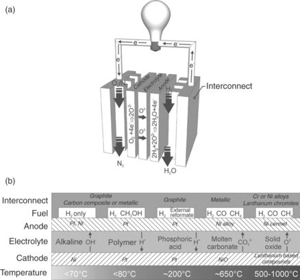
9.1 (a) Generic operation and major components of a fuel cell, using an SOFC operating on hydrogen as an example; (b) illustration of the materials of construction, typical fuel and operating temperature of the most common fuel cell types.
The most suitable primary sources of hydrogen-rich fuels (i.e., without requiring electrolysis of water) are hydrocarbons (HCs) and alcohols; these require different amounts of pre-processing depending on the fuel cell type. Table 9.1 summarises the fuel tolerance of different fuel cells and Fig. 9.2 shows the stages required to process the fuel. After desulphurisation (covered later in this chapter), HCs normally undergo steam reforming over a suitable catalyst to produce a mixture of H2 and CO, known as ‘syngas’. This can be used directly in high-temperature fuel cells, usually with an excess of steam to prevent carbon formation from the disproportionation of CO (the Boudouard reaction):
Table 9.1
Summary of fuel tolerance for different fuel cell types
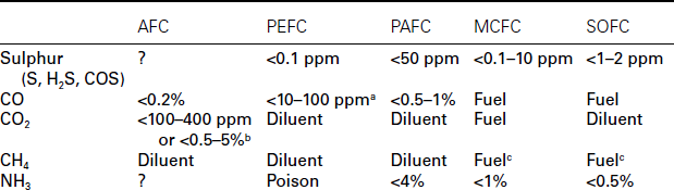
aStandard Pt anode catalysts can only withstand CO concentrations up to 10 ppm, and PtRu alloys up to 30 ppm. These limits can be extended by bleeding air into the anode and using alternative bi-layer catalysts.
bCO2 tolerance is highly dependent on the cell design. Strongly bonded nickel and silver electrodes with a circulating electrolyte can be tolerant, while platinum and carbon with an immobilised electrolyte are highly sensitive.
cInternal reforming is possible with MCFC and SOFC, making desulphurised natural gas a viable fuel. The long lifetimes required for some applications have not yet been demonstrated by these systems though.
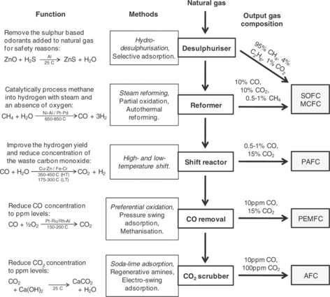
9.2 An overview of fuel processing for fuel cell systems. Each stage is highlighted in bold, and given with the most common methods that are used; for each stage, the primary method is highlighted in italics. A description of each stage is given at the far left, along with the ideal reactions for the primary method. Indicative ranges of gas composition after each stage are given to the right. Following the stages down from natural gas to each type of fuel cell on the right indicates which processing stages are required (Staffell, 2010).
SOFCs have the advantage of being the most fuel-flexible of the fuel cell technologies. Molten carbonate fuel cells (MCFCs) also operate at high temperatures and are able to use CO as a fuel. PAFC are tolerant to around 1% CO; however, the Pt catalyst in the PEFC is easily poisoned by CO (Cheng et al., 2007), and the significant amount of CO in syngas must be removed/converted by further processing, as illustrated in Fig. 9.2.
Nearly all types of fuel cell are poisoned to a greater or lesser extent by the presence of sulphur-based impurities, requiring desulphurisation down to the order of 10–100 ppm for the phosphoric acid fuel cell (PAFC) and SOFC, or much lower for the PEFC and AFC.
The aim of this chapter is to provide an overview of the issues involved in fuelling fuel cells; starting from the thermodynamics of reactions at the anode, through fuel processing and alternative fuels and concluding with a look at the deleterious effects of impurities and the fuels themselves on performance.
9.2 Thermodynamics of fuel cell operation and the effect of fuel on performance
Two separate reactions occur in a fuel cell, a reduction at the cathode and oxidation at the anode. For the common case of operation on hydrogen and oxygen from air, the overall reaction is
The oxidation and reduction proceed as follows:
For n electrons, the electrical work performed is nFE, where F is Faraday’s constant and E is the cell voltage. This represents the action of moving an electrical charge through an electrical potential field. Under reversible conditions, where no net current flows, the maximum electrical work is performed (nFEo), where Eo corresponds to the thermodynamic cell voltage. When maximum work is performed, this corresponds to the change in free energy (ΔG) for the reaction, and consequently
The free energy is a measure of the affinity and direction of the reaction. For a cell working in galvanic (fuel cell) mode, energy is released from the electrochemical reaction and ΔG is negative. The reaction enthalpy (ΔH) and entropy (ΔS) must also be considered in order to describe the efficiency of an electrolytic or galvanic process. Enthalpy is the heat delivered by a reaction (negative when heat is given out, as occurs for a galvanic process) and entropy describes the change in ‘order’ associated with the reaction (positive is associated with an increase in disorder or randomness of the system). The following well-known equation relates ΔG to ΔH and ΔS:
Therefore, for reactions with a decrease in disorder (negative ΔS), such as the reaction of hydrogen with oxygen to form water, ΔG is less than ΔH. The change in entropy is manifested as the generation of heat associated with the conversion of some of the chemical energy in the fuel. The thermodynamic efficiency (ηth) is expressed as the ratio of free energy to chemical energy (enthalpy) of the fuel:
Since for most reactions the entropy change is negative, the thermodynamic efficiency is <100%, as can be seen in Table 9.2. However, in some cases the reaction results in an increase in disorder (positive ΔS) (e.g.,formic acid) and the system takes heat in from the environment, so expressing an efficiency of greater than 100%, based on the thermal efficiency definition described earlier.
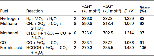
Figure 9.3 shows how the efficiency of a fuel cell varies with temperature for the hydrogen/oxygen combination, as well as that for a reaction with negative entropy change, that is, C + 1/2O2 CO, along with the variation in efficiency with temperature for a heat engine conforming to the ideal Carnot limitation. It can be seen that the theoretical maximum efficiency of a hydrogen-fuelled fuel cell at high operating temperature is less than that of an equivalent heat engine. However, in practice the irreversible losses that occur in fuel cells due to electrokinetic and ohmic resistances are lower at higher temperatures, which usually more than offset the loss of efficiency determined by the thermodynamics of reaction. Such kinetic issues also mean that the impressive thermodynamic efficiency of the direct carbon reaction is not achieved in practice, and certainly not at lower temperatures.
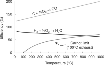
9.3 Graph showing the variation in efficiency for the reactions of carbon and hydrogen with oxygen as a function of temperature, in comparison to the maximum efficiency of a heat engine obeying the theoretical Carnot limitation.
9.2.1 Hydrogen
Fuel cells are inexorably linked with hydrogen, often generically referred to as ‘hydrogen fuel cells’. Indeed, for most fuel cell types hydrogen is the fuel of choice in terms of performance and longevity.
Hydrogen as a fuel benefits from a high gravimetric energy density (140.4 MJ kg−1 compared to 48.6 MJ kg−1 for gasoline) (Gupta, 2008) and is used extensively for the synthesis of chemicals such as ammonia and methanol. However, it is not found in its pure, uncombined form on Earth and must be produced from other compounds. Therefore, it is often considered to be an energy carrier rather than an energy source, and so is referred to as an ‘energy vector’. Along with the requirement to store and distribute hydrogen in a convenient and high energy density manner, the ability to produce it in large quantities in a cost effective and ‘environmentally friendly’ way is a major challenge to the realisation of a ‘hydrogen economy’.
Various methods of liberating hydrogen from chemical carriers exist, the most common of which uses methane as the feed source and results in the liberation of CO2 in the process. The ‘low-carbon’ credibility of hydrogen is therefore clearly compromised when it is generated from hydrocarbon feedstock. An alternative route to hydrogen is via the electrolysis of water or steam. This avoids the production of CO2 in the process itself; however, the low-carbon credentials are determined by the source of the electrical power (i.e., from renewable power sources or conventional hydrocarbonburning power stations), as well as the efficiency of the electrolysis process itself. The capital cost of the technology and the economics of operation are also major factors in determining the efficacy and long-term prospect for this source of hydrogen (Manage et al., 2011).
The majority of the world’s H2 is produced using steam methane reforming (SMR) (Gupta, 2008; Mueller-Langer et al., 2007). Depending on the purpose of the SMR plant (i.e., whether it is primarily for the production of either H2 or syngas), H2 will be produced at varying purities and compositional amounts. The other major ways of producing hydrogen from hydrocarbons are partial oxidation and gasification, which are described in the next section.
Electrolysis for the production of hydrogen is well known. Currently, most electrochemically generated hydrogen is produced using alkaline electrolysers at temperatures of around 80°C for a vast range of small-scale applications (Zeng and Zhang, 2010). Electrolytic generation is considered particularly useful for certain applications due to the high purity of the hydrogen produced. Proton exchange membrane (PEM) electrolysers generally provide a higher efficiency, whilst enabling pure hydrogen to be produced without the need for a separation process. However, it is the hightemperature operation of solid oxide electrolysis cells (SOECs) that affords significantly higher efficiency, based on both thermodynamic and kinetic benefits. The technical and economic merits of these processes have recently been analysed (Manage et al., 2011).
In addition to the generation of H2, its storage is a major technological challenge. Provided that this obstacle is overcome, the use of low-temperature fuel cells in many applications, particularly transportation, has a greater possibility to succeed. Common forms of hydrogen storage include: compressed cylinders, cryogenic cylinders, metal hydride or complex hydrides. Figure 9.4 compares the volumetric and gravimetric storage density of different hydrogen storage techniques (Cai et al., 2010). The perforated lines depict the ratio of operational time to volume (or weight), depending on the rate of consumption of the fuel.
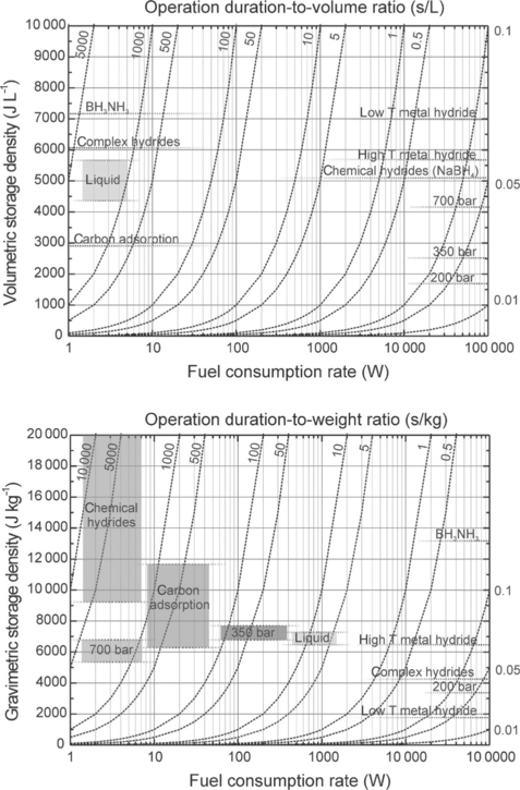
9.4 Hydrogen storage technology selection charts based on volumetric (top) and gravimetric (bottom) considerations (Cai et al., 2010).
9.3 Hydrocarbon fuels and fuel processing
The fact that hydrogen needs to be generated and the challenges of storing it at a practical size, weight and cost means that its generation on demand from available hydrocarbon fuels is likely to continue to be the major source of hydrogen.
A number of fuel processing options exist, the selection of which depends on the efficiency required, the fuel used, hydrogen purity, dynamic response and the size and cost of the plant. From the materials perspective, the main challenges for the catalysts used are to achieve high activity and selectivity whilst maintaining durability operating on impure feed and dynamic operation. Figure 9.2 shows a common route for fuel processing: desulphurisation, steam reforming, water–gas shift reaction and preferential oxidation of CO. These processes, along with others, are discussed in the following sections.
9.3.1 Fuel reforming
Reforming is the process of converting hydrocarbons into hydrogen by the reaction with steam or carbon dioxide. Steam reforming involves the following generic endothermic reaction and is typically achieved with an efficiency in the range of 70–80% (Mueller-Langer et al., 2007; Staffell, 2010):
This reaction requires heat and a supply of steam. Under normal operating conditions, an SOFC generates enough heat as a result of the electrochemical reaction and ohmic heating to drive this reaction. Since fuel is not completely consumed in a fuel cell, anode exhaust gas can be combusted with depleted air from the cathode in an afterburner to produce heat. This, or the direct combustion of some fuel, is required to service the reformer heat requirement for low-temperature fuel cell systems.
Steam must be raised to service the reformer; this is done by capturing the exhaust heat in a heat recovery steam generator fed by externally fed water or recycling the steam-rich anode products. During start-up, an external boiler is required to bring the system to operating temperature. This, and the relatively slow endothermic reforming reaction, means that steam reforming is poor at responding to transient load requirements and start/stop cycling.
The reforming reaction does not require a catalyst to occur; however, the reaction rate is improved and the size of the reformer is reduced by using one. The reforming catalyst must be active for the specific fuel used, tolerate the high temperature of operation (typically 750–800°C), resist poisons and coke formation, and not introduce a significant pressure drop.
Catalysts used for steam reforming are often based on Ni/NiO or Co formulations supported on materials such as magnesium alumina spinel (Rostrup-Nielsen, 1993). These compositions can be combined with alkali or alkali-earth compounds to reduce methanation and facilitate coke gasification to avoid carbon deposition.
Carbon dioxide (dry) reforming involves the endothermic reaction (∆H = 247 kJ mol−1 for methane) of hydrocarbons with CO2 to give a product with a H2/CO ratio of unity. The reaction takes place at a higher temperature (typically 900–1000°C) and 1–20 atmosphere pressure:
9.3.2 Partial oxidation
In partial oxidation (POX), fuel is partially combusted with a sub-stoichiometric amount of oxygen; the process allows larger hydrocarbons such as oils to be converted and is highly exothermic:
Thermal partial oxidation (TPOX) requires high operating temperatures, between 1250 and 1500°C and pressures of between 3 and 12 MPa, which means that a catalyst is not required. Due to the exothermic nature of the process, additional heat is not required as the heat produced is sufficient to maintain the operating conditions within the reactor. However, unlike SMR the process produces soot, which means that an additional cleaning process is necessary to remove solid particulates from the gas (Gupta, 2008; Holladay et al., 2009).
Catalytic partial oxidation (CPOX) reduces the temperature to the order of 800–900°C. Catalysts for CPOX include platinum group metals (PGMs, i.e., Pt and Ru), NiO–MgO, nickel modified hexa-aluminates on titaniaor ceria-containing supports (Ghenciu, 2002). The subject has been extensively reviewed by Bharadwaj and Schmidt (1995).
POX is more versatile than steam reforming as larger hydrocarbons can be used, and has a much faster reaction that SMR, so allows for smaller reactors and higher throughput. However, it produces hydrogen at a higher cost due to lower yields and efficiency, therefore SMR is usually favoured for large scale production of hydrogen (Gary and Handwerk, 2001).
9.3.3 Autothermal reforming
Autothermal reforming (ATR) combines the steam reforming reaction and fuel oxidation into a single unit, the exothermic oxidation providing the heat for the endothermic reforming process. ATR is popular for smallerscale hydrogen generation and affords higher H2 production than POX and faster start-up and response times than steam reforming. Independent control of the steam-to-carbon and air-to-fuel ratios means that effective heat management can be achieved.
Early ATR systems were composed of separate, but thermally integrated, burner and steam reformer. The challenge for single-unit ATR is that the catalyst must service (or at least be compatible with) both the steam reforming and partial oxidation reactions and their environment. Again, the choice of catalyst must be matched to the type of fuel used. Lighter hydrocarbons can use copper-based catalysts with longer chain molecules using Pt, Rh and Ru or ionconduction ceria supported non-noble metal formulation: Fe, Co, Ni (Ghenciu, 2002). PGM cermet catalysts with bi-functional properties have more recently been developed for ATR: the PGM services the dehydrogenation role and the oxide ion conducting properties of the ceramic component (e.g., CeO2, ZrO2, Bi2O5) perform the selective oxidation function (Ghenciu, 2002).
9.3.4 Water–gas shift reaction
The water–gas shift (WGS) reaction is used to increase the H2 and reduce the CO content of the reformate. This is done by reacting CO present in the mixture with steam, such that the following moderately exothermic reaction takes place (∆H0 = −41.2 kJ mol−1):
The WGS reactor is positioned directly downstream of the reformer and due to its exothermic nature benefits from lower operating temperatures.
The optimal temperature of operation is a balance between the thermodynamics of the reaction and the activity of the catalyst; for a single-stage WGS reactor it is usually in the range of 200–280°C. A well-designed WGS reactor should be able to reduce the CO content from a reformer down from around 10% to less than 5000 ppm.
There are a number of species present in the WGS reactor; several side reactions are possible which are dictated by the temperature and catalyst used. A significant amount of work has been dedicated to optimising the operating conditions and catalyst used for WGS; however, the mechanism of reaction is not yet fully understood. To improve conversion efficiency, the WGS reactor is often segregated into two zones: high-temperature shift (HTS) (350–400°C) and low-temperature shift (LTS) (180–240°C), each separated by an intercooler. In the HTS, Fe–Cr oxide is traditionally used, with Cu–ZnO–Al2O3 most commonly employed in the LTS. Using these catalysts, the HTS can reduce the CO content to ~3–5%, while the LTS reduces the concentration down to the order of 0.3–1% (Ghenciu, 2002). However, for fuel cell applications on the scale of individual vehicles or micro-CHP (Hawkes et al., 2009c), these catalysts are far from ideal due to the relatively low activity (needed for large reactors), lengthy pre-conditioning requirement and pyrophoric nature of Cu–ZnO. Consequently, non-precious metal catalysts that are active at low temperatures and PGM-based catalysts active over a broad temperature range and active at low loadings are the topic of ongoing research.
9.3.5 Carbon monoxide removal for low-temperature fuel cells
The low-temperature operation of PEFCs necessitates the use of high-performance precious metal electrocatalysts (i.e., Pt and Ru) which are highly sensitive to CO poisoning (Baschuk and Li, 2001). This makes it important to reduce the CO composition exiting the fuel processor to the order of 10–100 ppm to avoid appreciable performance degradation over extended periods of operation. Various approaches exist to achieve this; the most widely used being CO preferential oxidation (PROX)/oxygen bleed (Gottesfeld and Pafford, 1988):
However, complete selectivity for this reaction is impossible and the oxidation of hydrogen also occurs in parallel, so reducing the efficiency of the overall fuel processor. Assuming a 1% inlet composition of CO, a PROX reactor needs to have a CO conversion of over 99.5% to achieve a 50 ppm output. Such high activity would usually call for a PGM catalyst and indeed Pt-based catalysts (typically with Al2O3 support) tend to give the best results over the temperature range of 80–200°C (Ghenciu, 2002). Fe-promoted (Liu et al., 2002) and Ce-promoted Pt (Son and Lane, 2001) catalysts have been reported to improve conversion, particularly at lower temperatures.
9.3.6 Gasification
The gasification process operates by combusting either coal or biomass at high temperatures and pressures to produce syngas. There are three main types of gasification reactors: fixed-bed, fluidised-bed and entrained-flow reactors. Fixed-bed reactors were favoured when the technology was first introduced; however, fluidised-bed and entrained-flow reactors are more commonly used in industry today. A fluidised-bed reactor typically operates at temperatures of 800–950°C and pressures of around 25 bar. This process involves the introduction of either oxygen or air into the reactor with the coal/biomass particles until the particles act like a fluid. The entrained-flow gasifier operates at temperatures between 1200 and 1500°C and pressures between 30 and 40 bar. The feed is milled to small particles of ~100 µm diameter and dried before entering the reactor, where they react with the oxygen and steam that is also fed to the reactor. The syngas produced can undergo the WGS reaction to further improve the hydrogen yield (Gupta, 2008).
Gasification is a much faster reaction than both POX and SMR; however, the capital costs are greater as there are more pre-treatment processes required for coal than methane and the syngas needs more cleaning to remove particulates (Mueller-Langer et al., 2007; Holladay et al., 2009). In addition, gasification offers much lower efficiencies than SMR, of the order of 50–60% (Smith et al., 2005), and is not suitable for smaller-scale applications.
9.3.7 Internal fuel processing
From the previous sections it is clear that fuel processing adds significantly to the overall complexity, size and cost of a fuel cell system, as well as significantly reducing its efficiency. For high-temperature fuel cells, there exists the substantial advantage of being able to perform fuel processing within the fuel cell assembly. There are three ways that this can be implemented: (i)indirect internal reforming (IIR), whereby fuel and an oxygen source (e.g., H2 O and CO2) react to produce hydrogen and other small organic molecules within a reactor that is thermally integrated into the stack; (ii)direct internal reforming (DIR), whereby the fuel is actually reformed at the anode itself, and (iii) direct electrochemical oxidation, which involves direct oxidation of fuel molecules by the oxide ions passing through the electrolyte to the anode.
If direct electrochemical oxidation can be performed exclusively and carbon deposition can be avoided, no steam needs to be introduced to the system with its associated increase of plant complexity and lowering of open circuit voltage; resulting in a large improvement in overall efficiency. However, avoiding parallel carbon forming reactions is difficult in the absence of steam and is one of the main obstacles to achieving a technologically attractive system.
9.4 Methanol
Although performance and durability is likely to be greatest when operating on hydrogen, the previous section has shown that acquiring hydrogen and storing hydrogen has its issues. This results in more complex engineering and/or greater weight in the fuel cell and storage system. It is desirable to store a fuel in unpressurised liquid form that has good thermodynamic and kinetic performance when oxidised in a fuel cell. Methanol is considered to be a promising fuel in this regard. It is a clear, colourless, flammable liquid, with a moderate boiling point (67°C) and density (0.79 g cm−2), and is miscible with water in all proportions. As a liquid, it is easily transported and stored. However, it is a poison with small internal doses: inhalation or prolonged exposure causes blindness and is fatal at doses of 100–125 cm3. It is corrosive to many metals and burns with a flame that is invisible in daylight. Despite the hazardous nature of methanol it is widely regarded that it can be used as a safe fuel if properly managed. Repeated exposure to very small doses of methanol is not harmful (it is not a cumulative poison), nor is it carcinogenic or mutagenic.
Methanol can be easily produced from natural gas and has the significant advantage of being able to steam reform over suitable catalysts at temperatures as low as 200°C. Peppley et al. (2003) have reviewed the methods used to convert methanol to hydrogen external to the fuel cell; internal reforming of methanol in SOFCs has also been reported (Saunders et al., 2004). Methanol is considered to be a promising fuel for both high-temperature fuel cells, where it can be internally reformed or possibly undergo direct electro-oxidation, as well as for use in low-temperature fuel cells where its high energy density as a liquid is considered particularly attractive for portable applications.
9.4.1 The direct methanol fuel cell
The direct methanol fuel cell (DMFC) is a variant of the PEFC where the fuel is a mixture of methanol and water, typically of the order of 1 M in methanol. The reaction at the anode and cathode proceed as follows, respectively:
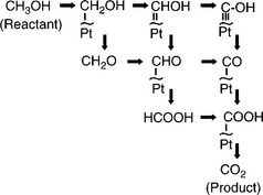
The thermodynamic cell potential associated with this combination of reactions is 1.2 V (assuming 1 M methanol in liquid water) and involves six electrons. It is therefore complex and does not occur in a single reaction. Figure 9.5 shows the oxidation of methanol and the various possible intermediates depicted in a ‘scheme of squares’. The complexity of the process means that the anode kinetics are much slower than for hydrogen; at low (operating) temperatures, the CO seen in the reaction scheme as an intermediate adsorbs strongly to Pt, blocking the surface and hindering electrooxidation. Electro-oxidation of the adsorbed CO is believed to involve the reaction of COads with Pt-OH sites at lower potentials:
and H2O at higher electrode potentials:
Slow anode kinetics and the problem of CO poisoning means that a major area of DMFC development involves understanding of the reaction mechanism and improving catalysts. The anode electro-catalyst must perform the bi-functional role of chemisorbing methanol as well as oxidising the intermediates. By adding extra components to conventional Pt-based catalysts, the rationale is that the Pt acts to chemisorb the methanol whilst the promoter provides oxygenated species (i.e., OHads) to support the oxidation of COads.
Other problems with the DMFC include the degradation of the electrolyte membrane by methanol; prevention of cathode flooding; removal of CO2 product gas and methanol cross-over to the cathode where it can react and create a mixed potential, so reducing the efficiency of the cell and decreasing fuel utilisation. Strategies for dealing with these include using thicker electrolyte membranes, diluting the methanol feed and modifying the electrolyte by either adding a layer of material that oxidises methanol before it reaches the cathode or incorporating functionality into the membrane that blocks methanol cross-over whilst still allowing proton migration such as the use of zeolites that act to ‘filter’ through protons but block the larger methanol molecules (Yoonoo et al., 2011).
9.4.2 Processing of methanol and direct use in solid oxide fuel cells (SOFCs)
Many of the reactions that occur within a high-temperature fuel cell fuelled by an alkane hydrocarbon/steam mixture also occur for a methanol-fuelled system. Methanol can be converted into hydrogen-rich mixtures suitable for SOFC feed via several reactions, including methanol steam reforming:
with further hydrogen being generated via the WGS reaction. It is unlikely that methanol decomposition or steam reforming will occur in a single step and several reaction mechanisms have been proposed (Rozovskii and Lin, 2003).
If the steam-to-carbon ratio is low, methanation reactions can also occur:
Carbon formation (coking) can occur via disproportionation of CO or reduction of CO, the reverse of which under conditions of high steam-tomethanol ratios acts to suppress carbon formation at higher temperatures.
In the case of methanol, direct electrochemical oxidation can be thought to occur, thus:
although this will most likely occur via an intermediate, for example (Mogensen and Kammer, 2003):
Workers at the University of Pennsylvania have reported direct oxidation of hydrocarbon fuel performed in the absence of steam and without significant carbon deposition using Cu-based anodes (Kim et al., 2001; McIntosh and Gorte 2004). Brett et al. (2005) have also demonstrated operation of an intermediate temperature solid oxide fuel cell (IT-SOFC) (Brett et al., 2008) directly on methanol using Cu-based anodes.
9.5 Other fuels
9.5.1 Biogas
The uncertainties associated with the production and storage of hydrogen and the CO2 emissions issues of operating directly on hydrocarbons raises questions about the fitness of fuel cells in the future low-carbon energy generation landscape. Operation on biofuel is one way to allay these concerns. There are various sources of biofuel/biogas for use in fuel cells. Anaerobic digestion of biomass is a common way of producing biogas and consists of a series of bacterial processes that convert organic compounds to a mixture that is rich in CH4 and CO2, as well as new bacterial cells to sustain the reaction.
The typical components in biogas are the following: CH4: 55–70%; CO2: 30–45%; hydrogen sulphide (H2S): 0–4000 ppm; siloxanes: 0–400 mg m−3; and mercaptanes: 0–100 ppm. Trace amounts of hydrogen, nitrogen, carbon monoxide, oxygen, ammonia and saturated or halogenated carbohydrates (0–100 mg m−3) are also present. Other chemicals, such as halides, often exist that are detrimental to fuel cell operation. These are common in landfill gas as well as in wastewater treatment gas (Schieder et al., 2003; Bove and Lunghi, 2005; Trogisch et al., 2005; Rasi et al., 2007; Cosoli et al., 2008; Deublein and Steinhauser, 2008).
During anaerobic biological processes the production of H2S mainly occurs because of the degradation of sulphur-containing proteins (e.g., methionine and cysteine) or the reduction of sulphate to H2S through sulphate-reducing bacteria (Gerardi, 2003). The fermentation of manure, biowaste and food waste shows typical concentrations in the range of 2000–6000 ppm in the biogas (Schieder et al., 2003; Bolhar-Nordenkampf et al., 2004; Cosoli et al., 2008). The relatively large proportions of H2S, siloxanes and mercaptans are particularly relevant to operation with fuel cells and the effect of such impurities is discussed later.
9.5.2 Ammonia
There has been a small but growing interest in using ammonia as a fuel, or rather as an energy vector, in fuel cells. It was originally promoted for alkaline fuel cells by Karl Kordesch in the early 1980s and first demonstrated in an SOFC by Farr and Vayenas (1980). Since then there has been sporadic interest, as reviewed by Ni et al. (2009). Studies have shown that SOFC performance using standard materials is comparable when operating on pure NH3 to a hydrogen-fed system. The only products of the reaction are N2 and H2O, with no detectable NOx produced. Ammonia has some advantages over hydrogen as a clean energy carrier and energy storage medium: its cost per unit of stored energy is much less than that of hydrogen, and it is easy to produce, store and transport, being easily liquefied. Ammonia has been used in the chemical industry for many years, so there is already an established infrastructure of technology and safety measures for its production and use. Although it is toxic and dangerous at levels above 500 ppm, any leakage of ammonia can be easily detected by its pungent odour – the olfactory detection limit is 0.4–2 wt. ppm, while the typical occupational exposure limit is 25 ppm. Hydrogen, conversely, is odourless and colourless and, although it has the advantage of being nontoxic, it is highly flammable and more difficult to detect.
Modern production methods of ammonia are very efficient, even from coal, and the existing production process involves inherent CO2 separation, enabling CO2 sequestration to be employed without additional CO2 scrubbing. Hansen et al. (2010) have studied the potential ‘well-to-power’ efficiency of electricity generation using an NH2 -fueled SOFC plant from various feedstocks, and found the overall efficiency of an energy chain with CO2 sequestration, even from coal feedstock, could be as high as 40%.
9.5.3 Hydrogen sulphide
Hydrogen sulphide is a highly poisonous, corrosive gas with a characteristic foul smell that is produced in vast quantities as a by-product of many industrial processes, such as the refining of fossil fuels. Since there is little commercial use for H2S, and it is dangerous to dispose of directly, it is usually converted in the Claus Process to elemental sulphur (e.g., for use in rubber manufacture), or SO2, which is eventually converted to sulphuric acid and used, for example, in the pharmaceutical industry. The Claus process is a highly exothermic partial combustion reaction, and it would be desirable to use the waste heat it produces as efficiently as possible. For this reason there has been some interest in employing fuel cells for so-called chemical co-generation of SO2 and electricity, by electro-oxidation of H2S in an SOFC. This type of usage would not require any additional fuel production, as with hydrogen, methanol and ammonia, and the H2S would effectively be a free source of fuel.
Although H2S is usually highly undesirable in H2- or CH4-fed fuel cells, due to it being corrosive and poisonous to nickel and other catalytic metals, it has been shown to be a feasible fuel of its own accord (Pujare et al., 1987; Yentekakis and Vayenas, 1989; Peterson and Winnick, 1998; Liu et al., 2001; Mukandan et al., 2004). Aguilar et al. (2004) have even reported an anode material which appears to preferentially oxidise H2S over H2. New materials are being developed, such as strontium-doped lanthanum vanadate (LSV) and various metal sulphides, which show promising results for long-term stability and conductivity (Vorontsov et al., 2008).
9.5.4 Solid carbon
A highly desirable use of fuel cells would be for direct electrochemical conversion of coal char (or even raw coal) into electric power, which would bypass the Carnot efficiency limitations of thermal cycles. However, there are obvious engineering challenges in designing a fuel cell to operate on solid fuel. The use of liquid anodes, such as molten tin (McPhee et al., 2009), bismuth (Jayakumar et al., 2010) or carbonate (Nabae et al., 2008), is one way to achieve the intimate contact between fuel and electrode required for effective reaction and charge transfer. Cooper is a pioneer of direct carbon (coal) fuel cells and has reviewed the development of this area (Cooper, 2007).
9.6 Deleterious effects of fuels on fuel cell performance
Fuel cell performance is generally thought to be acceptable for most applications. The focus is now shifting to maintaining this performance throughout the operational life of the units, or restricting degradation to an acceptable level. For stationary applications, it is assumed that a fuel cell system should be capable of a minimum lifetime of 40 000 h (with 8000 h of uninterrupted service at >80% rated power). Automotive applications have a lifetime target of 5000 h at a degradation rate of less than 1% per 1000 h; with up to 20 000 operational hours required for buses. Realising these degradation targets is essential if a fuel cell system is to be cost competitive based on the assumed higher electrical efficiency of fuel cells over other technologies (Hawkes et al., 2009a, 2009b).
The nature of the fuel is a significant factor in determining the durability of fuel cells and several of the main degradation mechanisms are discussed here.
9.6.1 Carbon deposition
In high-temperature fuel cells operating on carbon containing fuel, a range of reactions may occur, the extent and direction of which will be determined by the partial pressure of the reactants and products as well as the temperature (Offer et al., 2009). These reactions include reforming, WGS, cracking, methanation, polymerisation, hydrogenolysis and disporportionation. The dynamic equilibrium of these reactions can result in the formation of solid carbon on the surface of the anode which results in the deactivation of the electrode. The Boudouard reaction (Equation [9.1]) and hydrocarbon cracking are common routes to coke formation:
The nature of the carbon that forms is a function of the materials in the anode and the temperature of operation. Temperature-programmed oxidation studies provide an insight as to the nature of the carbon as a function of temperature, with carbon nanotubes reported between 275 and 550°C; char and amorphous coke between 550 and 725°C and graphitic whiskers above 725°C (He and Hill, 2007; Macek et al., 2007).
Coke formation can be avoided by introducing sufficient steam into the fuel feed stream. A steam-to-carbon (S/C) ratio of at least 2.5 is generally regarded to be sufficient to avoid carbon formation within an operational SOFC. This is particularly important at the entrance to an anode, since ‘downstream’ portions of the anode will inherently have a higher H2O and lower fuel composition as it gets consumed.
Most SOFC anodes are nickel based. Nickel is an excellent catalyst for coke formation and most of the electrode design work done to avoid or reduce the effect of carbon deposition has involved substitution or doping of Ni in the anode.
Macek et al. (2007) showed that the introduction of silver and copper mixed with Ni/YSZ reduced carbon deposition. Finnerty et al. (1998) showed that low levels of molybdenum (as little as 1% MoO3) decreased carbon formation by four times; and Gorte and Vohs (2003) and Brett et al. (2008) have shown that substitution of Cu for Ni substantially reduces coke formation for hydrocarbons and methanol, respectively.
9.6.2 Sulphur poisoning and removal
Sulphur is a known catalyst poison in many chemical processes, and fuel cells are no exception. Sulphur compounds are present in most fuels that are otherwise suitable for use in fuel cell systems, ranging from less than 10 ppm added as an odorant to natural gas, up to 3000 ppm in some anaerobic digester gases. The sulphur is present in a range of compounds such as carbonyl sulphide, alkyl disulphides, mercaptans, tetrahydrothiophene and benzothiophenes, depending on the source of the fuel. The range of sulphur compounds commonly found in fuels are summarised in Table 9.3.
Table 9.3
Summary of sulphur-containing compounds found in fuels
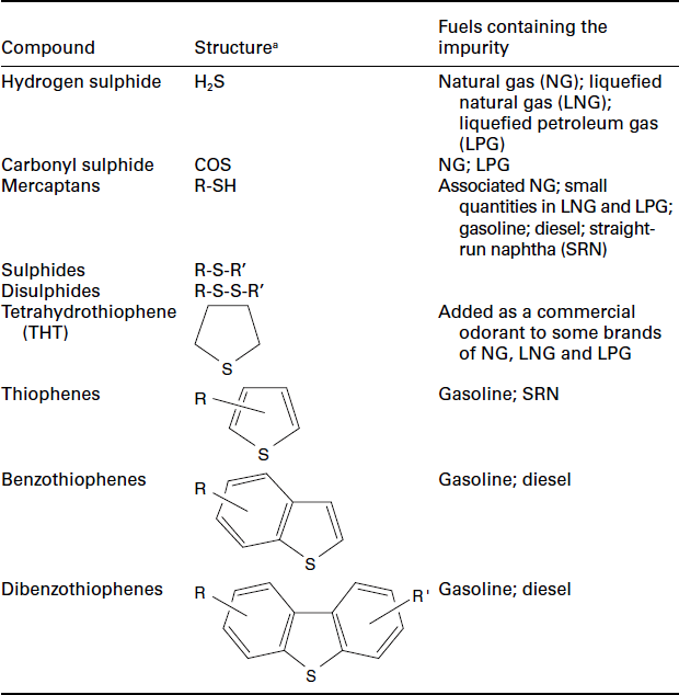
aR/R is an alkyl or phenyl substituent.
Source: Offer et al., 2009.
A fuel cell system would normally include a fuel desulphurising unit, using hydrodesulphurisation with ZnO, sulphur sorption (on activated carbon or a ceria-based sorbent), or a combination of both to remove sulphur from the fuel down to acceptable levels, possibly as low as a few parts per billion (ppb). Sulphur poisoning is a particular concern for fuels where desulphurisation below a few parts per million is prohibitively expensive or difficult, and also in situations where breakthrough may occur due to desulphuriser failure.
After reforming, the sulphur compounds are predominantly converted to H2S, and so this is used as a model sulphur poison in most studies. Due to the suitability for direct internal reforming in SOFCs, the effect of sulphur on these anodes is of particular interest to researchers; there is also a wealth of data from fixed-bed catalysis research where similar materials and thermodynamic conditions prevail. However, while it is generally agreed that the poisoning effect of H2S increases with decreasing temperature and that the impact is less at higher current density, there is little or no consensus on the degree of recovery of SOFC anodes from short-term exposure to various levels of H2S, and the longer term effects of sulphur poisoning are the subject of ongoing research (Offer et al., 2009).
Studies have found that at lower temperatures, typically between 600 and 800°C, reversible performance loss occurred at H2S concentrations as low as 0.2 ppm (Sasaki et al., 2006; Matsuzaki and Yasuda, 2000). Irrecoverable degradation occurred at 5–10 ppm H2S depending on temperature, while at higher temperatures, that is, 1000°C, up to 2 ppm H2S was tolerated without significant performance loss, and 50–100 ppm caused irreversible degradation.
Sulphur species must be removed down to an acceptable level for sustainable fuel cell performance – what this level is will depend on the operating conditions and specific materials used in the fuel cell. Various chemical, physical, and biological procedures are available for the removal of H2S. The target (around 0.1 ppm H2S) required for application in fuel cells is difficult to achieve with biological and physico-chemical procedures alone. Therefore, combinations can be used, such as a biological process for rough gas cleaning and adsorption for final cleaning, for example (Groenestijn and Kraakman, 2005; Deublein and Steinhauser, 2008; Osorio and Torres, 2009).
Regenerative sulphur scrubbing
Scrubbers and biological columns are commonly used for H2S removal. A water scrubber can be used to remove H2S since it has higher water solubility than methane, and the adsorption process is purely physical. The water used can be regenerated and recirculated.
In biological columns, bacteria that use H2S in their metabolism are used to clean the gas. Bacteria need to be immobilised in a packing material that gives physical support. Different micro-organisms and packing materials are currently being developed for this purpose (Pinjing et al., 2001; Groenestijn and Kraakman, 2005; Duan et al., 2006; Grove et al, 2007; Deublein and Steinhauser, 2008).
Packing materials used to date include either natural materials such as soil, compost, peat and wood chips, or synthetic materials such as ceramic saddles, polyethylene rings, polyurethane foam and activated carbon. When natural materials are used, the surface-to-volume ratios are low, which results in low volumetric reaction rate. Organic media typically needs to be replaced after 3–5 years, and this is difficult to be regenerated. The use of synthetic packing media has advantages such as larger specific surface areas and solid phase adsorption of contaminants, although humidified air must be used and nutrients must be supplied to service the living requirements of the bacteria (Duan et al., 2006).
To achieve an optimum balance and combination of the adsorption capacity with the biodegradation of H2S by bacteria, activated carbon can be used as a packing material (Trogisch et al., 2005). A biofilm is developed through culturing the bacteria in the presence of carbon pellets in mineral media. The limitations in this system are firstly that the accumulation of sulphate and excess biomass in the packing bed is problematic, but periodically washing the media bed by water irrigation can reduce the accumulation of excess biomass and oxidising products (e.g., sulphur). Second, the bed is found to dry out easily and needs to be washed periodically as the moisture content of biofilter media is a key parameter necessary for good performance. Too high a moisture level will inhibit the mass transfer from the gas phase to the biofilm or adsorption surface of the carbon. On the other hand, drying out of the media will harm the healthy growth of micro-organisms that are immobilised on the supporting media surface (Duan et al., 2006).
Tests using thiobacteria attached on a fixed-bed material, at normal operation conditions, have shown that the degree of H2S degradation was >90%. H2S concentrations in the cleaned gas of less than 50–100 ppm could be achieved (Schieder et al., 2003).
Non-regenerative sulphur scavenging
Sulphur scavenging is usually performed using a zinc oxide (ZnO) sorbent, typically within an exchangeable cartridge device; the reaction proceeds according to the following equation (Panopoulos et al., 2006):
The sulphur remains chemically bound inside the cartridge, which has to be replaced periodically so that the sulphur can be removed and the ZnO regenerated. Using ZnO cartridges, sulphur can be reduced to less than 1 mg m−3, but the operational costs are relatively high (Deublein and Steinhauser, 2008).
Zeolite materials are particularly suitable for adsorption removal processes, by virtue of their high selectivity and compatibility towards polar compounds. Hydrophilic zeolites with a high content of Al in their framework are generally more appropriate for adsorbing polar molecules such as H2S; while hydrophobic zeolites are effective in the entrapment of apolar molecules (Cosoli et al., 2008).
Bioscrubbers comprise an absorber in which H2S is absorbed in water and an aerated bioreactor in which sulphide is biologically converted into elemental sulphur, diluted caustic soda in the water is usually used. The biogas flows through the first column where H2S reacts with the caustic soda to form Na2S or NaHS (Groenestijn and Kraakman, 2005; Deublein and Steinhauser, 2008):
Through the other column flows air, so that the immobilised microorganisms remove the H2S from the caustic soda and regenerate brine (Groenestijn and Kraakman, 2005; Deublein and Steinhauser, 2008):
The elemental sulphur settles and is withdrawn at the bottom of the column. The caustic soda must be partly removed and neutralised due to the sulphate formation, in order to prevent the acidification of the scrubber.
The Claus process has been the standard of the sulphur recovery industry, but limitations and problems relating to composition may restrict its effectiveness for fuel cell applications. Traditional Claus plant may be used for sulphur recovery from a rich-feed gas stream, with at least 50% H2S by volume. However, for lower H2S content (5–50% volume) a modification of the traditional Claus plant is needed (McIntyre and Lyddon, 1997). In addition, acid gas feeds may contain undesirable components such as ammonia and hydrocarbons, which cause problems during processing. For an optimum conversion of H2S, a 2:1 H2S:SO2 ratio is required. The reactions involved in a Claus plant are as follows:
Sulphur recoveries in the range 96–97.5% are typical for a standard threebed Claus plant.
9.6.3 Particulates
The possibility of particles acting as impurities or poisons in fuels cells has received very little attention as yet in the literature, but is a subject of increasing interest, not least because of the emphasis currently placed on the effects on human health and environmental sustainability of nanoand micro-sized particles in the atmosphere. Particles with reasonable atmospheric lifetimes, and those usually considered the most relevant to human health, are those with aerodynamic diameters of approximately 10 μm down to particles of only a few nanometres in diameter. In terms of the numbers present in the atmosphere, those with diameters of 1 μm to 10 nm dominate. Particles found in ambient air usually are composed mainly of organic carbon, elemental carbon and inorganic salts, with much smaller quantities of other mineral, metals (including iron oxide and mercury) and water. Engineered nanoparticles found in ambient air, by definition, have a much more homogeneous composition – for example, titanium oxide, cerium oxide and zinc oxide engineered nanoparticles are common.
The effect of particles on fuel cell is multi-faceted. It is expected that the majority of fuel cell exposure to particles will occur in the cathodic side of the fuel cell if fed by ambient air. However, if it is quite feasible that particles may also enter the anodic side if the fuel production produces particles as a minor by-product, for example in some reforming reactions.
Once inside the fuel cell, the particles may begin to accumulate in the gas diffusion layer (GDL), clogging channels and reducing the pressure and flow of the gas feed, and therefore affecting the performance of the fuel cell in a fairly predictable manner. This is expected to be only a physical effect, and not dependent on the composition of the particles which are trapped. Recent work has shown that the trapping efficiency of a typical PEFC GDL is close to 100% at 1 μm, about 65–70% at 100 nm, and between 0% and 20% at 10 nm (Brown et al., 2011). Hence larger particles are likely to clog the GDL whilst smaller particles progress deeper into the fuel cell.
The particles which progress through the GDL are then likely to affect fuel cell operation by adhering to the active parts of the catalyst layer on the electrode. There are two mechanism of action: (1) physical: by simple blocking of the active catalyst areas available, affecting fuel cell performance in a predictable manner and (2) chemical: by reaction with the components within the particulate matter. The most important components of the particulate matter for considering chemical reactions are likely to be metallic components which may be able to react with the surface of catalysts like Pt, forming amalgams in the case of mercury, and thereby affecting fuel cell performance in a much less predictable manner.
It is possible that potential cycling regimes may help to clear particulate poisoning from the catalyst layers, but this will not alleviate GDL clogging.
9.7 Conclusions
A fuel cell without fuel is irrelevant. The fuel used defines the application, performance, durability and operating cost. Hydrogen, while being the fuel of choice for most fuel cells, is limited by the need to generate it from other chemical sources or use low-carbon electricity sources to electrolyse water. It has been shown that a wide range of fuels can be used in different types of fuel cell; in each case the fuel cell must be designed and operated with the fuel as the primary concern.
While improvements continue to be made in the understanding and performance of fuel cells themselves, similar improvements are required in the development of fuel processors – particularly their size, cost, complexity, ability to operate under dynamic conditions and regular stop/start conditions.
Biofuels are set to play an important role in the future of fuel cells; however processing and handling the range of components and impurities is a significant challenge. Finally, it should be noted that there is a serious lack of understanding of the effect of particulate matter on the durability of fuel cells. The physical and chemical affects are likely to be significant and cumulative; more effort should be directed at understanding these degradation mechanisms and how to avoid them.
9.8 Acknowledgements
The authors would like to acknowledge the EPSRC Supergen Fuel Cells programme for supporting the research of DJLB and NPB, and the EPSRC Supergen Flexnet programme for supporting IS. Funding supporting the NPL from the UK National Measurement System’s Chemical and Biological Metrology programme is also gratefully acknowledged.
9.9 References
Aguilar, L., Zha, S.W., Cheng, Z., Winnick, J., Liu, M.L. A solid oxide fuel cell operating on hydrogen sulfide (H2S) and sulfur-containing fuels’. Journal of Power Sources. 2004; 135:17–24.
Baschuk, J., Li, X. Carbon monoxide poisoning of proton exchange membrane fuel cells. International Journal of Energy Research. 2001; 25:695–715.
Bharadwaj, S.S., Schmidt, L.D. Catalytic partial oxidation of natural gas to syngas. Fuel Processing Technology. 1995; 42:109–127.
Bolhar-Nordenkampf, M., Friedl, A., Koss, U., Tork, T. Modelling selective H2S absorption and desorption in an aqueous MDEA-solution using a rate-based non-equilibrium approach. Chemical Engineering and Processing. 2004; 43:701–715.
Bove, R., Lunghi, P. Experimental comparison of MOFC performance using three different biogas types and methane. Journal of Power Sources. 2005; 145:588–593.
Brett, D., Atkinson, A., Cumming, D., Ramirez-Cabrera, E., Rudkin, R., Brandon, N.P. Methanol as a direct fuel in intermediate temperature (500–600°C) solid oxide fuel cells with copper based anodes. Chemical Engineering Science. 2005; 60:5649–5662.
Brett, D.J.L., Atkinson, A., Brandon, N.P., Skinner, S. Intermediate temperature solid oxide fuel cells. Chemical Society Reviews. 2008; 37:1568–1578.
Brown, R.J.C., Brett, D.J.L., Shearing, P.R. unpublished results, 2011.
Cai, Q., Brett, D.J.L., Browning, D., Brandon, N.P. A sizing-design methodology for hybrid fuel cell power systems and its application to an unmanned underwater vehicle. Journal of Power Sources. 2010; 195:6559–6569.
Cheng, X., Shi, Z., Glass, N., Zhang, L., Zhang, J., Song, D., Liu, Z.-S., Wang, H., Shen, J. A review of PEM hydrogen fuel cell contamination: Impacts, mechanisms, and mitigation. Journal of Power Sources. 2007; 165:739–756.
Cooper, J.F. Direct conversion of coal derived carbon in fuel cells. In: Basu S., ed. Recent Trends in Fuel Cell Science and Technology. New York: Springer; 2007:248–266.
Cosoli, P., Ferrone, M., Pricl, S., Fermeglia, M. Hydrogen sulphide removal from biogas by zeolite adsorption Part I. GCMC molecular simulations. Chemical Engineering Journal. 2008; 145:86–92.
Deublein, D., Steinhauser, A. Biogas from Waste and Renewable Resources.An Introduction. Weinheim, Germany: Wiley-VCH Verlag GmbH & Co. KGaA; 2008.
Duan, H., Koe, L.C.C., Yan, R., Chen, X. Biological treatment of H2S using pellet activated carbon as a carrier of microorganisms in a biofilter. Water Research. 2006; 40:2629–2636.
Farr, R.D., Vayenas, C.G. Ammonia high temperature solid electrolyte fuel cell. Journal of Electrochemical Society. 1980; 127:1478–1483.
Finnerty, C.M., Coe, N.J., Cunningham, R.H., Ormerod, R.M. Carbon formation on and deactivation of nickel-based/zirconia anodes in solid oxide fuel cells running on methane. Catalysis Today. 1998; 46:137–145.
Gerardi, M.H., The Microbiology of Anaerobic Digesters. Wastewater Microbiology Series. New Jersey, USA, Wiley-Interscience. 2003.
Gary, J.H., Handwerk, G.E. Petroleum Refining, Technology and Economics, 4th ed. Boca Raton, FL: CRC Press; 2001.
Ghenciu, A.F. Review of fuel processing catalysts for hydrogen production in PEM fuel cell systems. Current Opinion in Solid State and Materials Science. 2002; 6:389–399.
Gorte, R.J., Vohs, J.M. Novel SOFC anodes for the direct electrochemical oxidation of hydrocarbons. Journal of Catalysis. 2003; 216:477–486.
Gottesfeld, S., Pafford, J. A new approach to the problem of carbon-monoxide poisoning in fuel-cells operating at low-temperatures. Journal of Electrochemical Society. 1988; 135:2651.
Grove, J.A., Anderson, W.A., Moo-Young, M. Changes in the potential functional diversity of the bacterial community in biofilters. Applied Microbiology and Biotechnology. 2007; 77:741–747.
Groenestijn, J.W., Kraakman, N.J.R. Review: Recent developments in biological waste gas purification in Europe. Chemical Engineering Journal. 2005; 113:85–91.
Gupta, R.B. Hydrogen Fuel, Production, Transport and Storage. CRC Press; 2008.
Hansen, J.B., Madsen, J., Nielsen, J.U., Christiansen, N., Ammonia as SOFC fuel – Assessment from coal or biomass to power and heat. Proceedings of Lucerne European SOFC Forum, 2010:51–58.
Hawkes, A., Brett, D.J.L., Brandon, N.P. Fuel cell micro-CHP techno-economics: Part 1 Model concept and formulation. International Journal of Hydrogen Energy. 2009; 34:9545–9557.
Hawkes, A., Brett, D.J.L., Brandon, N.P. Fuel cell micro-CHP techno-economics: Part 2 Model application to consider the economic and environmental impact of stack degradation. International Journal of Hydrogen Energy. 2009; 34:9558–9569.
Hawkes, A., Staffell, I., Brett, D., Brandon, N. Fuel cells for micro-combined heat and power generation. Energy & Environmental Science. 2009; 2:729–744.
He, H., Hill, J.M. Carbon deposition on Ni/YSZ composites exposed to humidified methane. Applied Catalysis A. 2007; 317:284–292.
Holladay, J.D., Hu, J., King, D.L., Wang, Y. An overview of hydrogen production technologies. Catalysis Today. 2009; 139:244–260.
Jayakumar, A., Lee, S., Hornés, A., Vohs, J.M., Gorte, R.J. A comparison of molten Sn and Bi for solid oxide fuel cell anodes. Journal of Electrochemical Society. 2010; 157:B365–B369.
Kim, H., Park, S., Vohs, J.M., Gorte, R.J. Direct oxidation of liquid fuels in a solid oxide fuel cell. Journal of the Electrochemical Society. 2001; 148:A693–A695.
Liu, M., He, P., Luo, J.L., Sanger, A.R., Chuang, A.K. Performance of a solid oxide fuel cell utilizing hydrogen sulfide as fuel. Journal of Power Sources. 2001; 94:20–25.
Liu, X., Korotkikh, O., Farrauto, R. Selective catalytic oxidation of CO in H2: Structural study of Fe oxide-promoted Pt/alumina catalyst. Applied Catalysis A General. 2002; 226:293–303.
Macek, J., Novosel, B., Marinsek, M. Ni-YSZ SOFC anodes Minimization of carbon deposition. Journal of the European Ceramic Society. 2007; 27:487–491.
Manage, M.N., Hodgson, D., Milligan, N., Simons, S.J.R., Brett, D.J.L. A techno-economic appraisal of hydrogen generation and the case for solid oxide electrolyser cells. International Journal of Hydrogen Energy. 2011; 36(10):5782–5796.
Matsuzaki, Y., Yasuda, I. The poisoning effect of sulfur-containing impurity gas on a SOFC anode: Part I. Dependence on temperature, time, and impurity concentration. Solid State Ionics. 2000; 132:261–269.
McIntosh, S., Gorte, R.J. Direct hydrocarbon solid oxide fuel cells. Chemical Reviews. 2004; 104:4845–4865.
McIntyre, G., Lyddon, L., Claus sulphur recovery options. Bryan Research and Engineering, Inc – Technical paper. 1997.
McPhee, W.A.G., Boucher, M., Stuart, J., Parnas, R.S., Koslowske, M., Tao, T., Wilhite, B.A. Demonstration of a liquid-tin anode solid-oxide fuel cell (LTA-SOFC) operating from biodiesel fuel. Energy Fuels. 2009; 23:5036–5041.
Mogensen, M., Kammer, K. Conversion of hydrocarbons in solid oxide fuel cells. Annual Review of Materials Research. 2003; 33:321–331.
Mueller-Langer, F., Tzimas, E., Kaltschmitt, M., Peteves, S. Techno-economic assessment of hydrogen production processes for the hydrogen economy for the short and medium term. International Journal of Hydrogen Energy. 2007; 32:3797–3810.
Mukandan, R., Brosha, E., Garzon, F.H. Sulfur tolerant anodes for SOFCs. Electrochemical and Solid-State Letters. 2004; 7:A5–A7.
Nabae, Y., Pointon, K.D., Irvine, J.T.S. Electrochemical oxidation of solid carbon in hybrid DCFC with solid oxide and molten carbonate binary electrolyte. Energy & Environmental Science. 2008; 1:148–155.
Ni, M., Leung, M.K.H., Leung, D.Y.C. Ammonia-fed solid oxide fuel cells for power generation A review. International Journal of Energy Research. 2009; 33:943–959.
Offer, G.J., Mermelstein, J., Brightman, E., Brandon, N.P. Thermodynamics and kinetics of the interaction of carbon and sulfur with solid oxide fuel cell anodes. Journal of the American Ceramic Society. 2009; 92:763–780.
Osorio, F., Torres, J.C. Biogas purification from anaerobic digestion in a wastewater treatment plant for biofuel production. Renewable Energy. 2009; 34:2164–2171.
Panopoulos, K.D., Frida, E., Karl, J., Poulou, S., Kakaras, E. High temperature solid oxide fuel cell integrated with novel allothermal biomass gasification Part I: Modeling and feasibility study. Journal of Power Source. 2006; 159:570–585.
Peppley, B.A., Amphlett, J.C., Mann, R.F., Catalyst development and kinetics for methanol fuel processingVielstich, W., Gasteiger, H.A., Lamm, A., eds. Handbook of Fuel Cells Fundamentals, Technology and Applications; Vol. 3. John Wiley & Sons, Ltd, 2003:131–140.
Peterson, D., Winnick, J. Utilization of hydrogen sulfide in an intermediatetemperature ceria-based solid oxide fuel cell. Journal of the Electrochemical Society. 1998; 145:1449–1453.
Pinjing, H., Liming, S., Zhiwen, Y., Guojian, L. Removal of hydrogen sulfide and methyl mercaptan by a packed tower with immobilized micro-organism beads. Water Science and Technology. 2001; 44:327–333.
Pujare, N.U., Semkow, K.W., Sammells, A.F. A direct H2S/air solid oxide fuel cell. Journal of the Electrochemical Society. 1987; 134:2639–2640.
Rasi, S., Veijanen, A., Rintala, J. Trace compounds of biogas from different biogas production plants. Energy. 2007; 32:1375–1380.
Rostrup-Nielsen, J.R. Production of synthesis gas. Catalysis Today. 1993; 18:305–324.
Rozovskii, A.Y., Lin, G.I. Fundamentals of methanol synthesis and decomposition. Topics in Catalysis. 2003; 22:137–150.
Sasaki, K., Susuki, K., Iyoshi, A., Uchimura, M., Imamura, N., Kusaba, H., Teraoka, Y., Fuchino, H., Tsujimoto, K., Uchida, Y., Jingo, N. H2S poisoning of solid oxide fuel cells. Journal of the Electrochemical Society. 2006; 153:A2023–A2029.
Saunders, G.J., Preece, J., Kendall, K. Formulating liquid hydrocarbon fuels for SOFCs. Journal of Power Sources. 2004; 131:23–26.
Schieder, D., Quicker, P., Schneider, R., Winter, H., Prechtl, S., Faulstich, M. Microbiological removal of hydrogen sulfide from biogas by means of a separate biofilter system: Experience with technical operation. Water Science and Technology. 2003; 48:209–212.
Smith, J.M., Van Ness, H.C., Abbott, M.M. Introduction to Chemical Engineering Thermodynamics. McGraw-Hill; 2005.
Son, H., Lane, A.M. Promotion of Pt/γ-Al2O3 by Ce for the preferential oxidation of CO in H2. Catalysis Letters. 2001; 76:151–154.
Staffell, I., Fuel Cells for Domestic Heat and Power: Are They Worth It? Ph.D. thesis. University of Birmingham. 2010.
Trogisch, S., Hoffmann, J., Bertrand, L.D. Operation of molten carbonate fuel cells with different biogas sources: A challenging approach for field trials. Journal of Power Sources. 2005; 145:632–638.
Vorontsov, V., Luo, J.L., Sanger, A.R., Chuang, K.T. Synthesis and characterization of new ternary transition metal sulfide anodes for H2S-powered solid oxide fuel cell. Journal of Power Sources. 2008; 183:76–83.
Yentekakis, I.V., Vayenas, C. Chemical cogeneration in solid oxide fuel cells: The oxidation of H2S to SO2. Journal of the Electrochemical Society. 1989; 136:996–1002.
Yoonoo, C., Dawson, C.P., Roberts, E.P.L., Holmes, S.M. Nafion/mordenite composite membranes for improved direct methanol. Journal of Membrane Science. 2011; 369:367–374.
Zeng, K., Zhang, D. Recent progress in alkaline water electrolysis for hydrogen production and applications. Progress in Energy and Combustion Science. 2010; 36:307–326.