
Rare-earth magnets: properties, processing and applications
Abstract:
This chapter considers the background to the rare-earth magnets and their applications. The intrinsic characteristics of a ferromagnet are described and, in the case of the transition metals Fe, Co and Ni, these are related to the coupling of the unpaired spins of the 3d-electrons. The combination of the 4f electron behaviour of the rare-earth metal such as Sm or Nd combined with that of the 3d-electron behaviour of the transition metal, Co or Fe, gives rise to strong spin-orbit coupling and to magneto-crystalline anisotropy, that is, a distinct easy axis of magnetisation. The c-axis, uniaxial anisotropy of the hexagonal intermetallics SmCo5, Sm2(Co,Fe,Cu,Zr)17 and tetragonal Nd2Fe14B, combined with magnetic domain pinning in the case of the 2/17 magnets, gives rise to the very large improvement in magnetic properties exhibited by these materials. The processing of these magnets is described in some detail with some emphasis on the role of hydrogen in the processing of the NdFeB-type magnets. The chapter concludes with a description of how the magnetic properties are exploited in device performances with particular reference to electrical machines. Emphasis is placed on the application of these magnets in the generation of renewable energy and on their application in electric and hybrid electric vehicles.
19.1 Introduction
Magnetic materials of many different types continue to play a critical role in the generation, distribution and utilisation of energy. They are both an underpinning technology in existing equipment and infrastructure, and a key enabling technology for emerging future applications, for example, the move towards increased generation from renewables, the more efficient use of energy in domestic and industrial settings and in the emerging market for all-electric and hybrid electric vehicles. The breadth of applications for magnetic materials and the scale they cover are very substantial, from devices with dimensions of a few microns at ratings of μW through to single machines of many metres in length with ratings of 1 GW.
Magnetic materials exhibit a wide spectrum of magnetic properties which are often tailored to meet the demands of particular applications. They can be classified very broadly into soft or hard magnetic materials, although this rather sweeping categorisation inevitably has its limitations for classes of material which sit near the boundary. There are many intricate aspects of behaviour and performance which distinguish hard magnetic materials from their soft magnetic counterparts, the most elementary difference being the ease with which they can be magnetised.
Soft magnetic materials can be readily magnetised and demagnetised and indeed in many applications may well undergo many such cycles of magnetisation within 1 s, for example, the 50 Hz AC magnetisation of a transformer core. Their principal role in magnetic devices is to provide a high-permeability path for the main working magnetic flux of the device.
In contrast, hard magnetic materials, which are also commonly referred to as permanent magnet materials (the terminology adopted throughout this chapter), are much more difficult to magnetise and subsequently demagnetise, and hence once magnetised as part of their manufacture remain in this magnetised condition throughout the service life of the device, acting as a permanent and fixed source of magnetic flux.
This chapter focuses on hard or permanent magnetic materials, which have become ubiquitous in modern life with the greater adoption of electrical systems for performing ever-more tasks. More specifically, in this chapter we will describe and discuss the principles, processing and applications of rare-earth magnets based on the compounds: SmCo5, Sm2(Co,Fe,Cu,Zr)17 and Nd2Fe14B. Rare-earth magnets have developed over the past 45 years to become critical components in engineering systems, providing the excitation flux for many different types of rotating electrical machines, linear actuators, sensor systems and latching/holding devices. In many application domains, systems based on high performance rare-earth magnets offer the highest level of power density, efficiency and precision of all the competing technologies. By way of example, they are widely used in computer disk drives and hybrid electric vehicles.
19.2 Properties of permanent magnetic materials
19.2.1 What is a ferromagnetic material?
A useful starting point in understanding the behaviour of permanent magnets is to consider the fundamental behaviour of ferromagnetic materials.1,2 The very special feature of these materials is the spontaneous alignment of the magnetic moments of the individual atoms. In the ferromagnetic metals, Fe, Co, and Ni, these arise predominantly from the spin contribution of the 3d-type electrons. However, under equilibrium conditions, the bulk material does not exhibit an external magnetic field because the total energy of the system is minimised by the formation of ‘magnetic domains’ which form a closed magnetic circuit and hence eliminate any external field. This is illustrated in Fig. 19.1 and the response to the application of an external magnetic field (H) is to begin to align these domains with a large increase in the total field and this contribution is called the magnetisation (M) which reaches saturation (Ms) when all the domains are aligned in the direction of the applied field. The value of Ms is proportional to the number of unpaired 3d-electron spins and therefore decreases in going from Fe to Co to Ni. The value of Ms also decreases with increasing temperature due to progressive thermal disorder and the ferromagnetic state disappears completely at a particular temperature called the Curie point (Tc). This effect is totally reversible and the ferromagnetic state reappears on cooling below Tc. The Curie points for Fe, Co and Ni are 1043, 1393 and 631 K, respectively, and these indicate that the ferromagnetic coupling (exchange energy) is strongest in Co. The Ms and Tc are intrinsic properties of a ferromagnet.
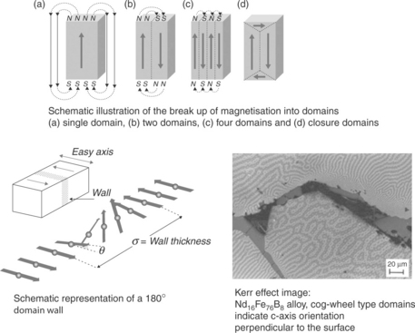
19.1 Schematic representation of magnetic domains. (Source: A. J. Williams: www.magnets.bham.ac.uk.)
Another intrinsic property is the magneto-crystalline anisotropy (MCA) which, in the case of Fe, Co and Ni is a consequence of the relatively weak coupling between the spin and orbital moments of the 3d-electrons. In the case of the rare-earth metals on the other hand, the 4f spin-orbit coupling is much more pronounced giving rise to much stronger MCAs. The consequence of this spin-orbit coupling can be that, within a particular crystalline structure, there is an easy direction of magnetisation and this is illustrated schematically for a hexagonal metal such as Co in Fig. 19.2, where the easy magnetisation direction is along the c-axis and is an example of uniaxial MCA (UMCA). This effect is much more pronounced in a crystal structure where there is a combination of ferromagnetic transition metal and a rare-earth metal, for example, SmCo5, Sm2(Co,Fe,Cu,Zr)17 and Nd2Fe14B. This essential characteristic for permanent magnets based on these compounds will be discussed later in the chapter.
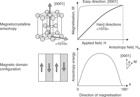
19.2 Uniaxial magneto-crystalline anisotropy in, for example, hexagonal cobalt. (Source: A. J. Williams: www.magnets.bham.ac.uk.)
To become a permanent magnet the domains have to remain aligned when the external field is removed or applied in the opposite direction. This leads to the phenomenon of hysteresis (from the Greek ‘to lag’). This gives rise to the properties of remanence (Br) when the external field is at zero and the intrinsic coercivity (Hcj) when M is reduced to zero. Fortunately, these are extrinsic properties and can be controlled by modifying the microstructure of the material. The resulting bulk magnetic behaviour of permanent magnets which leads to their utility for many electromagnetic devices can be illustrated by reference to its magnetic hysteresis loop, which captures both magnetisation and demagnetisation characteristics.
19.2.2 Hysteresis characteristics
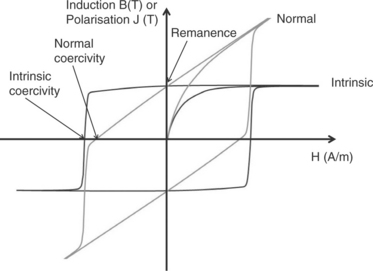
The hysteresis characteristics can be expressed in terms of either ‘intrinsic’ properties, a format preferred by material scientist, or the so-called normal properties which tend to be preferred by engineers concerned with the application of these materials. The intrinsic characteristic shows the relationship between the magnetic field strength (H) in the magnet and its magnetic polarisation (J), where J = μ0M and μ0 is the permeability of free space. In the case of the normal characteristic, this shows the relationship between the magnetic field strength (H) in the magnet and the net magnetic flux density (B). A schematic representation of a typical hysteresis loop for a high-performance permanent magnet is shown in Fig. 19.3. The characteristics are related simply by the formula B = μ0H + J. Despite this simple relationship, many data sheets from magnet manufacturers provide both characteristics.
It is the ability of a permanent magnet to act as a permanent and nominally lossless source of flux in a magnetic circuit that gives rise to their widespread use in many different types of devices. Predicting the behaviour of a permanent magnet in service requires a detailed consideration of its full demagnetisation characteristics under all envisaged operating conditions, and indeed may include measured data on ageing effects such as irreversible flux losses due to prolonged exposure to high temperatures. However, there are several features of the hysteresis characteristics which are used as key measures of performance:
Remanence
The remanence (Br) corresponds to the flux density in the material at zero magnetising field strength. Although a permanent magnet does not operate at its remanence in any practical device, it provides a useful measure of the flux-producing capability of a given material grade, although the actual flux produced is also determined by the combination of magnet and device geometries.
Coercivity
The intrinsic (Hcj) or normal coercivities (Hcn) correspond to the magnetising field strengths at which the polarisation or flux density become zero. It provides a useful, but by no means complete, indication of the ability of a given material to withstand demagnetisation under the influence of an externally applied field. It similarly provides an indication, albeit indirect, of the difficulty in initially magnetising the material during component manufacture.
Recoil permeability
This property is the slope of the linear region of the normal second quadrant demagnetisation characteristic. The recoil permeability is often expressed as a quantity relative to the permeability of free space μ0. For high-performance rare-earth magnets, the relative recoil permeability falls into a narrow range of values between 1.03 and 1.10 or so.
Maximum energy product
This is the maximum value of the product of flux density (B) and magnetising field strength (H) at any point on the second quadrant normal demagnetisation characteristic. It is widely used as a short-form designation by manufacturers to identify different grades within their range of materials. It should be used with a caution in terms of a stand-alone measure of magnet performance, since enhanced energy product is often accrued at the expense of demagnetisation withstand capability or maximum operating temperature limits. Selecting the dimensions of a magnet piece such that it operates at its maximum energy products ensures the minimum volume required to achieve a given magnetic energy in a working airgap. Adopting such design principles may be appropriate in designing holding magnets or static field sources. However, in the majority of electrical machines, the airgap flux density achieved by operating at this point is lower than is desired because of the knock-on effects on the remainder of the machine dimensions. Hence, in the design of electrical machines it is usual to operate the magnet at a flux density higher than that which corresponds to the maximum energy product. For a perfectly square intrinsic hysteresis loop (i.e. a relative recoil permeability of 1.0) the maximum energy product is given by Br2/4. An estimate of the upper limit on the energy product can be derived by considering the idealised theoretical case of a high-coercivity permanent magnet based on 100% iron. If such a material could be realised, it would exhibit a (BH)max value of ~ 925 kJ/m3 based on the Ms value of this metal. Clearly such a combination of properties is extremely unlikely because of the weak spin/orbit coupling and the absence of a uniaxial structure such as a tetragonal or hexagonal structure exhibiting a strong UMCA. So far this has only been achieved by combining iron (or cobalt) with a rare-earth metal, with the inevitable dilution of the 3d-element component.
Loop squareness
An important practical consideration is the squareness of the intrinsic hysteresis loop and one way of expressing this property is the ratio of the J at 10% Hcj to Jr. A perfectly square loop would give a value of 1.00.
Temperature coefficients ofremanence and coercivity
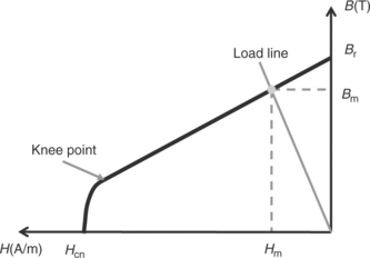
These coefficients, which should remain reasonably constant over the range of the recommended operating temperatures range of a given material, indicate the fractional change in remanence and coercivity with temperature. Although a useful and concise means of predicting the effect of temperature on device performance, single-value temperature coefficients (or indeed a series of slightly different coefficients which cover prescribed ranges of temperature) do not capture the full behaviour of a permanent magnet as a function of temperature, specifically in terms of tracking the ‘knee point’ (shown in Fig. 19.4) of the demagnetisation characteristic with varying temperature. Hence, in the design of permanent magnet devices which are exposed to significant demagnetising fields at elevated temperatures, it is essential to consider the full demagnetisation characteristic.
19.2.3 Flux producing capability of a permanent magnet component
The concept of a working-point on the normal B–H characteristic is a useful means of estimating the flux produced by a particular geometry of magnet under a given set of conditions. Such an approach assumes a uniform B and H throughout the magnet, whereas in practical permanent magnet pieces, there will be some degree of spread in the working points at localised regions throughout the magnet.
A previously unmagnetised magnet begins its excursion around the hysteresis loop from a working point at the origin. Prior to being used in a device, a permanent magnet component must be magnetised, a procedure which involves exposing the magnet to a high-intensity magnetic field strength. The high levels of field required to ensure full magnetisation, which can be of the order of 4T and above for high-performance magnets, are usually achieved with pulsed magnetic fields produced by the discharge of a capacitor bank into a magnetising fixture which comprises an appropriate arrangement of coils. In response to this externally applied magnetising field, the magnet working point moves along the initial magnetisation curve into the first quadrant.
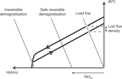
On removal of the applied field, the working point returns along a different curve ending up at some point in the second quadrant of the B–H characteristic, as shown in Fig. 19.4. The location of this working point is determined by the so-called load line, which in turn is derived from a combination of the magnet dimensions and the effective permeance of the magnetic circuit into which the magnet is incorporated. In the absence of any other magnetising or demagnetising fields, the magnet sits at this working point as a source of constant magnetic flux.
In some devices, the magnet will remain at this operating point throughout its entire service life. In other devices such as electrical machines and actuators, the permanent magnets are subjected to further magnetising and demagnetising fields produced by current-carrying coils during normal operation. These cause the magnet working point to move along the hysteresis characteristic from its original steady working point as shown in Fig. 19.5. Providing that the excursion of the working point during demagnetisation remains on the linear portion of the characteristic, the excursion is entirely reversible and the magnet returns to its original working point with no loss of flux. If, on the other hand, the demagnetising field strength is sufficient to drive the working point beyond the knee point of the characteristic on removal of the demagnetising field, the magnet working point returns along an essentially parallel characteristic with a permanent loss of flux. This irreversible demagnetisation can only be remedied by fully re-magnetising the magnet, a procedure which in most cases would involve disassembly of the machine into its constituent components. This is considered in many cases as a catastrophic failure mode, and great care is taken in the design of the machine and in the specification of the wider system to ensure that the working point remains on the linear portion of the characteristic under all predicted conditions.
In addition to an ability to produce high levels of magnetic flux by virtue of a large remanence, and the ability to resist demagnetisation which arises from a high intrinsic coercivity, there are many other magnetic, physical and electrical properties which are desirable, and in some applications essential. The ideal high-performance permanent magnet would exhibit ease of magnetisation to aid manufacture, a high Curie temperature, low temperature coefficients of remanence and coercivity, good intrinsic corrosion resistance allowing for their use without a protective coating, low cost, high electrical resistance and high mechanical strength.
19.3 Improving the properties of permanent magnetic materials
19.3.1 The magnetic triangle
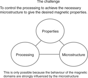
The only intrinsic property in the hysteresis loop is the saturation polarisation, Js, all the others are extrinsic and hence form part of the magnetic triangle shown in Fig. 19.6. Here the challenge is to control closely the processing conditions in order to achieve the necessary microstructure to give the desired magnetic properties. The microstructural features that might need to be taken into account are:
• grain size and uniformity of grain size,
• smoothness of the grain boundaries,
• presence of blocking phases at the boundaries,
• degree of alignment of the anisotropic ferromagnetic phase,
• type and distribution of precipitates,
Some or all of these features can have an influence on the properties of a particular permanent magnet and it should be noted that the domain wall widths (see Fig. 19.1) can be of a similar scale to these microstructural features.
19.3.2 Coercivity mechanisms in permanent magnets
As noted previously, achieving a high value of coercivity and maintaining a significant fraction of this coercivity over a wide operating temperature range is a highly desirable property for a permanent magnet. The large range of coercivity values exhibited by the different types of permanent magnets (e.g. some grades of Nd2Fe14B being some 50 times higher than grades of Alnico) stem from the different coercivity mechanisms at play in various magnet types. The various mechanisms are summarized in Table 19.1.
Table 19.1
The various coercivity mechanisms which operate in different PM materials
| Coercivity Mechanism | Materials |
| Shape anisotropy and single domain particles | AINiCo |
| Uniaxial magnetocrystalline anisotropy + nucleation | SrFe12O19, SmCo5, Nd2Fe14B |
| Uniaxial magnetocrystalline anisotropy + pinning | Sm2(Co,Fe,Cu,Zr)17 |
| Single-domain particles | Melt-spun NdFeB |
The AlNiCo magnets1,2 were the first major step forward after the earlier steel-based magnets and were developed first in Japan in the mid-1930s. They depend on the solid-state precipitation of needles of a ferromagnetic, Co-rich phase in a non-ferromagnetic (or weakly ferromagnetic) matrix. The development of coercivity depends on the formation of single domain particles and on the shape anisotropy factor such that it is easier to magnetise along the length of the needle rather than at right angles. This is a smaller energy advantage than that achieved by the MCA mechanism, and hence much smaller coercivities are achieved, the highest being of around 120 kA/m (compared with > 2500 kA/m for Nd(Dy)FeB-type magnets). Over about 30 years, progressive improvements in the magnetic properties of the AlNiCo have been achieved by:
• improving the aspect ratio of the precipitates by adding additional elements such as Ti,
• aligning the orientation of the precipitates by applying a magnetic field during annealing,
• improving the overall alignment of the grains by directional solidification of the cast ingot prior to precipitation.
The next important group of permanent magnets involved the combination of UMCA and a nucleation mechanism for the development of coercivity. The origins of this coercivity mechanism are shown in Fig. 19.2 and the first prerequisite is a uni-axial crystal structure such as hexagonal or tetragonal. The presence of a discrete UMCA along the c-axis gives rise to an easy axis of magnetisation and this results in the presence of 180° domains (forming Bloch walls). Once these are all aligned in the same direction by the application of an appropriate magnetising field, then the formation of reverse domains requires a large increase in the energy. This energy barrier is lowered considerably by the presence of lower-energy, reverse domain nucleation sites such as irregularities at the grain boundaries.
The first important group of permanent magnets to exploit this combination were those based on the hexagonal oxide, strontium (and barium) ferrite (SrFe12O19). This is still a very important category of permanent magnets and has many cost-sensitive applications, particularly in the automotive and consumer electronics sectors.3 Unfortunately, because it is a ferri-magnetic phase with a significant proportion of the Fe moments aligned in the opposite direction, there is a much reduced Br and hence only modest values of BHmax are achieved (typically up to 40 kJ/m3). The ceramic nature of these magnets means that they are very easy to process, are not sensitive to eddy-current generation during cyclic operation and exhibit excellent corrosion resistance. A unique feature of these magnets is an improvement in the coercivity with increasing temperature.
Fortunately, the magnetic moments of the light rare earths like Sm and Nd couple parallel with Co or Fe respectively. The rare-earth magnets therefore are a very important group of functional materials, the properties of which have improved steadily over the past 50 years since their first appearance as magnets based on the intermetallic SmCo5 in 1965. Karl Strnat4 was the first to recognise the importance of the substantial MCA exhibited by the rare-earth metals such as samarium associated with the strong spin-orbital coupling of the 4f-type electrons. Thus, when combined with the 3d-type transition metal cobalt in the CaZn5 - type hexagonal compound as shown in Fig. 19.7, the 3d/4f combination results in a strong coupling and a large UMCA such that the easy direction of magnetisation lies along the unique c-axis of the hexagonal cell < 0001 > and the hard direction < 1100 > lies within the basal plane. Strnat recognised that the important consequence of this combination of 4f and 3d electronic behaviour is that, in a single crystal or in an aligned powder compact, once magnetised along the c-axis then this would represent a very stable energetic state and hence a strong resistance to demagnetisation.
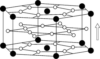
19.7 The hexagonal CaZn5-type intermetallic SmCo5 (![]() – samarium,
– samarium, ![]() – cobalt). The arrow indicates the direction of easy magnetisation.
– cobalt). The arrow indicates the direction of easy magnetisation.
In the nucleation model shown schematically in Fig. 19.8a, the microstructure is modified in order to minimise the number of reverse domain nucleation sites. In the case of SmCo5 this can be achieved by a slow cool from the sintering temperature of around 1473–1123 K. For NdFeB magnets, a significant improvement in coercivity and loop shape can be achieved by a post-sintering anneal of 923 K for 1 h. In the case of the latter, this improvement has been ascribed to further smoothing of the grain boundaries by the liquid grain boundary material.
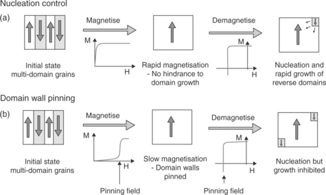
19.8 Origins of coercivity. (a) Nucleation behaviour, (b) domain pinning. (Source: A. J. Williams: www.magnets.bham.ac.uk.)
In the case of the rare-earth magnets based on the Sm2(Co,Fe,Zr,Cu)17 alloys (2/17 magnets)5 the high coercivities are achieved by a combination of UMCA and domain wall pinning (Fig. 19.8b). This requires a much more complicated post-sintering heat treatment compared with those for SmCo5 and NdFeB. The domain pinning results in a distinctly different first-quadrant magnetisation behaviour compared with that of the nucleation-type systems. This is because a pinning field Hp has to be overcome before saturation can be achieved. This means that significantly higher fields are required to achieve saturation and this makes in situ magnetisation much more difficult in the case of the 2/17 magnets.
A general expression for the coercivity1 (Hc) is given by
K1 = c -axis anisotropy constant (assuming K1 >> K2),
α(T) = temperature-dependent parameter describing the reduction of crystal field by defects as well as misaligned grains,
Neff = parameter describing the demagnetising effects of internal stray fields.
The first term describes the combination of the UMCA with the temperature dependent α parameter (which is < 1.0) and describes the reduction of the UMCA factor by defects such as misaligned grains. Neff describes the demagnetising effect of internal stray fields such as those produced by features such as grain-boundary ledges. This equation shows why the actual coercivity is considerably smaller than the theoretical value given simply by 2K1/Js
19.3.3 Historical development of permanent magnets
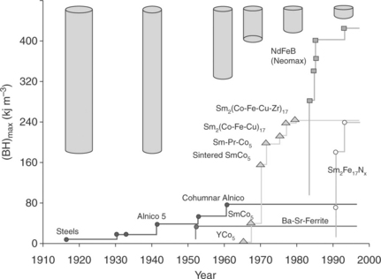
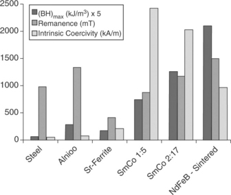
It is interesting to reflect briefly on the advances in permanent magnet properties that have accrued over the past 100 years or so through a combination of the discovery of new types of material and improved processing. As mentioned previously, the maximum energy product provides a useful figure of merit of permanent magnet performance. The evolution of (BH)max over the past 100 years is shown in Fig. 19.9, together with the equivalent volume and dimensions of the permanent magnets (shape anisotropy being the dominant factor for the steels and the Alnicos). The progress in the maximum energy product does not provide the full picture in terms of advances in key properties, particularly with regard to their application in high power density electrical machines. Figure 19.10 also shows the dramatic improvement in the intrinsic coercivity, Hcj, which came about with the advent of the rare-earth-based magnets. As noted previously, Hcj for NdFeB can be increased considerably by the partial substitution of Nd by Dy but this has major cost and resource implications.6
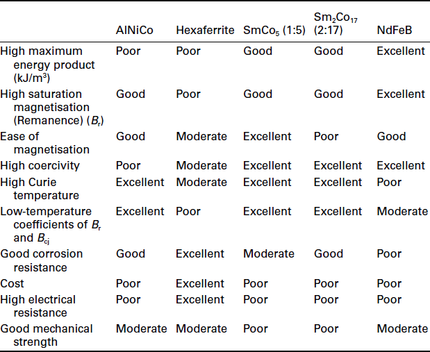
The data in Figs 19.9 and 19.10 are for operation at room temperature. However, in many applications, the magnets are required to operate over a range of temperatures. The relatively low Curie temperature of Nd2Fe14B (585 K) in combination with the nature of the particular coercivity mechanism dictates that, at temperatures around 423 K and above, SmCo5 with a Curie temperature of 993 K and the 2/17 magnets with a Curie temperature of around 1100 K can exhibit better overall performance. Table 19.2 summarises, in a qualitative manner, the key properties of all the permanent magnets currently in use.
19.4 Processing of permanent magnets
19.4.1 Processing of SmCo5 type magnets
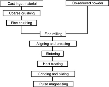
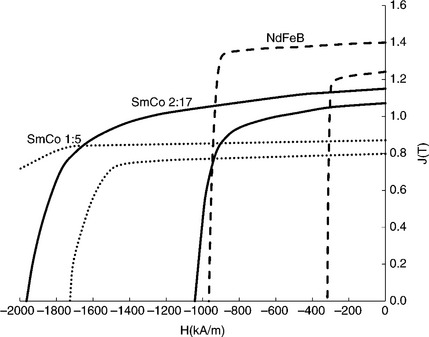
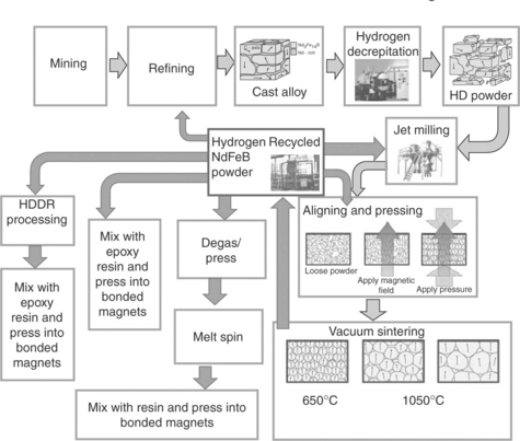
SmCo5 was the first of the family of rare-earth-based permanent magnets4,6 and, as mentioned previously, exploited the very pronounced UMCA combined with a nucleation-type coercivity mechanism. The processing routes for the fully dense sintered magnets are shown in Fig. 19.11 and there are two main production routes. In one case, the starting material is a cast ingot produced by induction melting the constituents in an inert atmosphere and, in the other case, the starting material involves the reduction of Sm2O3 with pure calcium, the so-called Goldschmidt or reduction/diffusion process. A final slow cool to 1123 K is essential in order to develop the full coercivity (from around 80 kA/m in the absence of a slow cool to around 3200 kA/m). No clear, unequivocal microstructural evidence has been found to explain this effect and this illustrates the often very subtle microstructural changes which can have a profound influence on reverse domain nucleation. Typical second-quadrant demagnetisation curves for a commercial grade of SmCo5 at 298 K and 473 K are shown in Fig. 19.12. Although this material exhibits a reduced remanence, Br, compared with that of 2/17 and NdFeB-type magnets, the demagnetisation characteristics have excellent linearity even up to temperatures of 573 K. Polymer-bonded magnets can be produced from the SmCo5 powder but they exhibit rather poor corrosion resistance due to the reactive nature of the powder.
19.4.2 Processing of Sm2(Co,Fe,Cu,Zr)17 type magnets
In an attempt to improve the magnetic performance by increasing the Co to Sm ratio, the binary phase 2/17 (Fig. 19.13) was investigated. Unfortunately, the UMCA factor and structural stability were not sufficient to create a permanent magnets based on the single-phase alloy and hence considerable efforts were expended over some 10 years to create a precipitation hardened magnet and this evolved into a typical composition of Sm2(Co0.82Fe0.1Cu0.05Zr0.03)17.

19.13 Crystal structure of the 2:17 matrix phase (grey symbols are Sm, black symbols are a mixture of Co and Fe). The arrow indicates the direction of easy magnetisation.
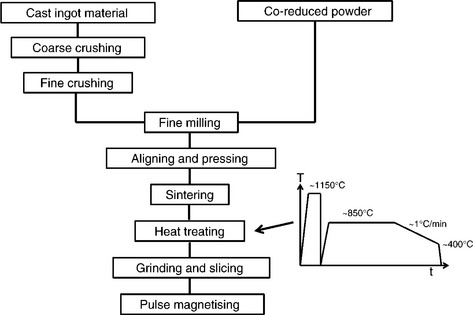
The processing routes are shown in Fig. 19.14. (It should be noted that these materials can also be produced by the Goldschmidt process which involves the reduction of the oxides by calcium.) This involves a more complicated and hence protracted procedure than that employed for the magnets based on SmCo5 involving a solution treatment at around 1423 K, a quench to room temperature and then a rapid heating to the ageing temperature of around 1123 K. After holding at this temperature for a set period, the magnet is then cooled at around 1 K per min to ~ 673 K and then quenched to room temperature. This treatment is designed to produce an appropriate microstructure, a typical example of which is shown in Fig. 19.15. This consists of a cellular microstructure of approximately 100 nm diameter. After the annealing process, the cell boundaries approximate to the 1/5 composition with an enrichment in the Cu and Co concentration. The Zr additions enhance the substitution of the Co by the Fe and produces a lamella phase which is thought to enhance the diffusion of Cu atoms along the interface with the matrix. The change in the MCA at the cellular boundaries results in domain wall pinning and hence enhanced coercivity. The ultrahigh-temperature grades of these magnets have an enhanced Cu content.8
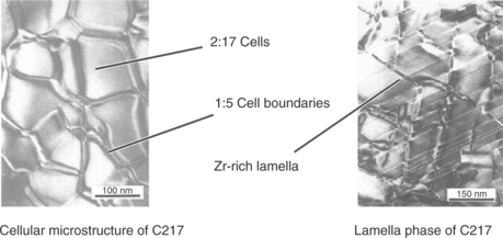
19.15 Typical microstructure of 2/17 magnet as revealed by TEM micrograph.7
Figure 19.12 shows some typical demagnetisation characteristics for a Sm-rich 2/17 magnet at 298 K and 473 K. Because of the high cobalt content, the 2/17 type magnets exhibit a high Curie temperature (~ 1100 K) and good corrosion resistance and are therefore favoured in aerospace and hazardous chemical environments.
19.4.3 Processing of NdFeB type magnets
Because of the strong dependence of the 1/5 and 2/17 magnets on cobalt and because of the uncertainty in the supply of this metal prevalent in the 1970s, there was a strong drive to find an Fe-based alternative. In the early 1980s the discovery of permanent magnets based on the tetragonal compound Nd2Fe14B (Fig. 19.16) was announced both by the Sumitomo Corporation in Japan9 and by General Motors in the USA.10 The Japanese discovery was based on an anisotropic, fully dense, sintered magnet with compositions slightly richer in Nd compared with that of Nd2Fe14B. This produced a grain boundary, low melting point eutectic mixture which resulted in the liquidphase sintering process and produced a microstructure which is effective in inhibiting the nucleation of reverse domains. This microstructure could be optimised by a final anneal at 923 K for 1 h. Initially, the overall processing sequence for these magnets was essentially the same as that for the SmCo5 magnets (without the Goldschmidt process).
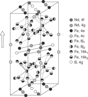
19.16 Crystal structure of Nd2Fe14B (expanded c-axis for clarity). The arrow indicates the direction of easy magnetisation.
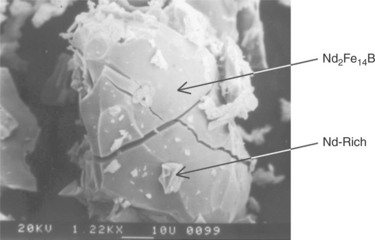
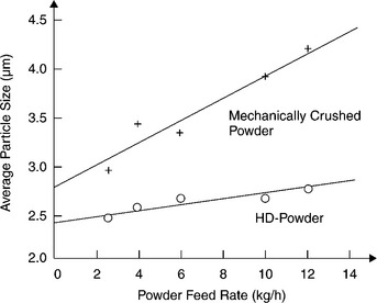
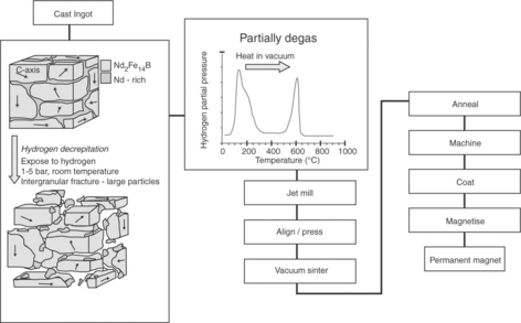
Over the intervening years, the production of NdFeB-based sintered magnets has been modified and one of the most significant modifications was the substitution of mechanical crushing by the HD (hydrogen decrepitation) process.11 This process had already been applied successfully to the production of SmCo5 and Sm2(Co,Fe,Cu,Zr)17 magnets but had not been adopted commercially in the case of these magnets. Early studies showed that the cast NdFeB-type alloys absorbed hydrogen (or non-explosive mixtures of hydrogen with gases such as nitrogen) at around 1 bar pressure and at room temperature. These studies indicated that the process is initiated in the Nd-rich material at the grain boundaries where NdH2.7 is formed. This is an exothermic process and is followed by the formation of a hydrogen solution within the Nd2Fe14B matrix phase. The consequent differential expansion results in the decrepitation of the bulk material by a combination of inter- and trans-granular fracture. A single grain of the matrix, Nd2 Fe14B phase, produced by the HD process is shown in Fig. 19.17 and it can be seen that this grain also contains trans-granular cracks, and on the surface there is grain boundary debris of the NdH2.7 material. A major advantage of the HD powder is that it is very friable (as would be expected from Fig. 19.17) and this behaviour is shown in Fig. 19.18, where the average particle size of the HD powder is much less dependent on the powder feed rate to the jet mill than the bulk crushed material.12,13 This represents a very significant increase in the capacity of the jet mill. Overall, it has been estimated that the use of hydrogen reduces the processing cost of NdFeB-type magnets by around 25% and the HD process is now the preferred method of manufacture.
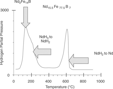
The essential aspect of hydrogen processing is that it is completely reversible and all the hydrogen is removed from the alloy during the vacuum sintering process. The degassing behaviour13 can be followed by pressure measurements during vacuum degassing and these are shown in Fig. 19.19. These indicate a three-stage degassing process which reflects the relative binding energies of the hydrogen in the various phases. The sequence is that hydrogen is desorbed first from the Nd2Fe14B matrix phase around 423 K, followed by the partial degassing of the NdH2.7 to NdH2 around 473 K and finally, the complete loss of hydrogen from the NdH2 grain boundary component at around 873 K to form Nd which then forms a major part of the liquid eutectic phase. Once the liquid phase is formed there is progressive sintering of the initial powder compact and almost full densification is achieved by holding at around 1323 K for 1 h. Currently, it is not a net-shape process and the final dimensions of the sintered magnets are achieved by processes such as centre-less grinding, thus producing significant amounts of magnet waste.
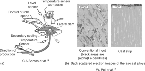
Further developments have included the production of ultra-high (BH)max (> 400 kJ/m3, > 50 MGOe) magnets and this necessitated the employment of alloy compositions close to that of the stoichiometric phase, Nd5Fe14B. This phase is known to form by a peritectic reaction and hence, in the normal book-mould castings, the presence of free Fe is a common feature.13 This can require prolonged, high temperature homogenisation treatments of the cast material and hence additional processing costs. This problem has been obviated by the use of strip casting14 to produce the alloys and this technique is shown schematically in Fig. 19.20a together with a comparison, Fig. 19.20b, of the typical microstructures of a conventional casting and some cast strip.15 The main differences are the complete absence of any free Fe in the cast strip together with a much finer columnar grain size and a very uniform distribution of the Nd-rich material at the grain boundaries. This is an ideal precursor microstructure for the subsequent HD process.
To achieve the full (BH)max potential, it is also necessary to improve the degree of alignment of the particles in the powder compact and this requires the partial degassing of the HD powder prior to the alignment process (Fig. 19.21). This removes hydrogen from the matrix phase with a resultant significant increase in the UMCA coefficient K1 and this gives rise to an improvement in the degree of alignment of the particles on application of the alignment field with a consequent increase in the (BH)max value.
It is now possible to achieve (BH)max values of around 470 kJ/m3 (59 MGOe) which is within almost 90% of the theoretical maximum of 525 kJ/m3 (65MGOe).1 Improvements in the processing of sintered magnets are ongoing and future developments16 could include the production of press-less magnets, recycling of scrap magnet and the recycling of hydrogen or its subsequent use as a fuel.17 It can be noted that the current annual production of NdFeB magnets is around 100 000 tonnes and if these magnets were all produced by the HD process then this would correspond to around 430 tonnes of degassed H2 which could provide the fuel for around 86 000 fuel cell cars for journeys of 585 km each. Alternatively, the hydrogen could be employed to power fuel cells within the manufacturing unit. The employment of recycled hydrogen strengthens the case for large-scale manufacture of these magnets.
Other elements are added to NdFeB for the following reasons:
• improvement of the corrosion resistance,
• increase the Curie temperature which is only 583 K for Nd2Fe14B,
• improvement of the grain boundary wetting to aid sintering and inhibit reverse domain nucleation,
The most effective element with regard to increasing the UMCA is Dy and this element substitutes for Nd, both within the matrix and at the grain boundaries.13,18 This increases markedly the room temperature coercivity which can compensate for the decrease which occurs on heating. Thus, in applications where the NdFeB-type magnets are exposed to elevated temperatures the magnets contain significant levels of Dy.
Dy has two major disadvantages: being a heavy rare-earth element, the large Dy moment (10.6μB) is aligned anti-parallel to the aligned Fe and Nd (3.4μB) moments, thus reducing the overall saturation magnetisation (Ms) and hence the remanence (Br). The other drawback is that Dy is one of the rare rare-earth elements and hence is very expensive and in short supply.6,19
This means that considerable efforts19 are now being made to either limit the amount of Dy employed in NdFeB-type magnets or to eliminate it altogether. One way of achieving the former is to target the Dy at the surface of the magnet and/or at the grain boundaries. In this way, the Dy will have the requisite effect on the coercivity with little or no reduction in the remanence because it is not substituted in the matrix phase. The challenge is to be able to control the necessary elemental distribution reproducibly in a mass-production process. Another related course of action is to reduce the average grain size of the sintered magnet which will increase the coercivity without Dy or with a much reduced level. Typical second-quadrant curves for a NdFeB-type magnet without significant levels of Dy are shown in Fig. 19.12. These curves illustrate clearly the need to increase the coercivity at room temperature for an elevated temperature application.
Bonded NdFeB-type magnets
This chapter concentrates on the fully dense, sintered magnets but bonded NdFeB-type magnets are also an important category which are used in a wide variety of applications. The advantage of these magnets is that they can be produced in large numbers in net-shape form. The disadvantages are that they have significantly reduced values of (BH)max because, in the case of the injection-moulded magnets, around 60% by volume is occupied by the magnetic material and this increases to around 80% in the case of compression-bonded magnets. There is a further reduction because the magnetic material is usually isotropic giving around 50% of the maximum Br and around 25% of (BH)max.
Magnets based on melt-spun material
As mentioned at the beginning of this chapter, the announcement of NdFeB magnets was from both Sumitomo9 and General Motors.10 The GM product was a melt-spun version of the NdFeB alloy (grain size of ~ 20 nm) and the three products are MQI, a bonded isotropic magnet, MQII, a fully dense hot-pressed magnet and MQIII, a fully dense, hot-pressed uniaxially anisotropic or radially anisotropic magnet. These are all illustrated schematically in Fig. 19.22. The coercivity in these cases is achieved by the grains being less than single domain size. Attempts have been made to improve the Br values by producing melt-spun Fe-Nd2Fe14B composites and these magnets exhibited enhanced values of Br but reduced coercivities.20
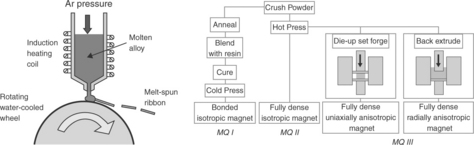
19.22 Variety of NdFeB-type magnets based on melt-spun ribbon. (Source: A. J. Williams: www.magnets.bham.ac.uk.)
Magnets based on the hydrogenation, disproportionation, desorption and recombination (HDDR) process
Hydrogen can 0also be employed to produce coercive powder which can be used to make bonded magnets. If the NdFeB-type alloys are heated in hydrogen rather than in a vacuum, then at around 923 K the matrix, Nd2Fe14B phase undergoes disproportionation21 according to the reaction shown in Fig. 19.23. As with the HD process, this is completely reversible, and recombination occurs when the hydrogen is removed but the material now has a uniform grain size of around 300 nm which results in significant coercivity. If the absorption and desorption processes are carefully controlled then anisotropic powder can be produced with a large increase in the (BH)max.13,22,23 The complete process is referred to as the hydrogenation, disproportionation, desorption and recombination (HDDR) process.
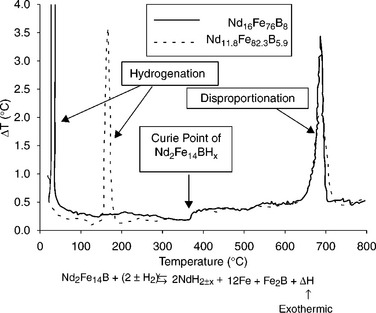
19.23 Description of the HDDR process using DTA measurements.21
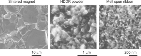
The grain sizes of the three main types of NdFeB magnet are shown in Fig. 19.24.
Recycling of sintered NdFeB magnets
The penetration of NdFeB permanent magnets into many commercial products since their discovery in the 1980s has given rise to rapidly increasing volumes of NdFeB-type magnets in devices which reach the end of their useful service life. This is particularly marked in hard disk drives when the astonishing advances in data storage density results in rapid obsolescence of products. This trend is likely to accelerate with the growth in hybrid electric vehicles, each of which can contain several kilograms of NdFeB. There is therefore growing interest in processes for the cost-effective recycling of NdFeB magnets. Hydrogen has found a new use in the recycling and selective removal of assembled sintered NdFeB-type magnets and the various recycling options17,24 are summarised in Fig 19.25.
19.25 The various recycling options for NdFeB magnets.2
19.5 Properties of commercially manufactured permanent magnets
Table 19.3 summarises the range of properties available from the main categories of permanent magnet materials, the data being drawn from commercially available mainstream grades of materials. It does not include development grade materials nor rather specialist grades such as 2/17 magnets for very high temperatures (> 623 K). The values shown for a given category of material in Table 19.3 are those for magnets that are essentially fully dense, which are manufactured in most cases by sintering or, in the case of Alnico, also by casting. There are a plethora of different grades of bonded magnets in which a permanent magnet powder is combined with an appropriate bonding material at volume fractions up to 80% or so. Bonded magnets tend to have rather dilute properties compared to those shown in Table 19.3 because, as discussed previously, most powders suitable for bonding have lower intrinsic properties and there is a reduced volume fraction of magnetic material in the final component.
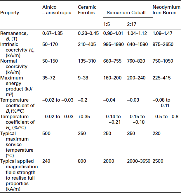
As shown by the data in Table 19.3, within a given category of material, there is a widespread range of properties available from various commercially produced grades. The various grades within a particular material system are achieved by employing different compositions, processing conditions, forming methods, etc. The various grades produced by manufacturers are tailored to the demands of different applications, often with a significant degree of trade-off between properties. By way of example, NdFeB grades at the top end of the remanence range have very limited elevated temperature capability (as low as 323 K in some cases) and are only capable of resisting modest levels of demagnetising field. They are therefore suitable for devices requiring high airgap flux densities with little or no externally applied fields and which operate at, or near, room temperature - for example, permanent magnet arrays for NMR scanners. In contrast, grades of NdFeB towards the lower end of the remanence range tend to have the highest maximum operating temperature capability and are able to resist high levels of demagnetising field. Such grades are therefore an appropriate choice for operation in high power density devices operating in harsh temperature conditions, for example, under-bonnet automotive motors.
As will be apparent from Table 19.3, the rare-earth materials exhibit vastly superior magnetic properties to ceramic ferrite (SrFe12O19) and Alnico magnets. However, the large cost differential between the low-cost ceramic ferrites and rare-earth magnets ensures that, despite their modest magnetic properties, ceramic ferrites remain a very important segment of the worldwide market for permanent materials, still accounting for some 50% of the total market by value.6 Although the various Alnico magnets can exhibit high values of remanence, they tend to have very modest coercivities, and hence are prone to demagnetisation. Indeed, the knee-point of the higher remanence grades is so far up the second-quadrant demagnetisation characteristic that some geometries of magnet self-demagnetise - that is, the working point is already beyond the knee-point without the application of any external demagnetisation field. Although rarely adopted in products targeting low cost or high power density, they continue to find applications in legacy designs and in niche applications where temperature stability is a paramount consideration, notably sensing systems.
2/17 and NdFeB magnets offer, by some distance, the best combination of properties for high-performance devices. Although NdFeB exhibits the best magnetic properties up to 473 K or so, with a cost advantage over 2/17, the greater intrinsic stability of 2/17 to corrosion and its ability to reliably operate in high-temperature environments ensures that they remain the preferred material in many high-value and safety-critical applications, notably in aerospace.
The importance of ensuring that material selection and device design take full account of the worst-case temperature conditions is clearly illustrated by the data in Table 19.3. Almost all aspects of the magnetic performance of the different materials diminish with increasing temperature, in some cases quite markedly. A notable exception is the positive temperature coefficient of coercivity of ceramic ferrite. This behaviour means that electrical machines equipped with ceramic ferrite magnets are most at risk of irreversible demagnetisation at low temperature, such as cold-start in automotive applications, and this dictates that the magnets must be dimensioned appropriately for these conditions.
It is worth noting that, even within one specific grade produced by one manufacturer, there are rather wide tolerance bands on many key properties by the standards of many functional materials. By way of example, for a high-temperature grade of NdFeB, even manufacturers of highest-quality materials still tend to quote minimum values of remanence which are some 95% of the typical value. In some applications which require close control of magnet flux, for example, magnets for sensors or small brushed DC machines operating directly from fixed DC voltages, it may prove necessary to calibrate each individual magnet by precisely controlled partial demagnetisation to achieve a tighter tolerance on the flux level in the assembled device.
The mechanical properties of permanent magnets, particularly sintered materials, are relatively poor with wide uncertainty bands, particularly under tension. As a consequence, they are rarely, if ever, considered as structural elements in component design.
An often overlooked property of permanent magnet materials is the electrical resistivity. In most electrical machines there is some degree of time-varying magnetic fields throughout the magnet volume, which could be caused by permeance variation in the magnetic circuit, due for example to the presence of slots in the stator core, or through so-called armature reaction fields produced by the stator currents. These time-varying fields result in induced voltages in the magnet themselves which in turn drive circulating eddy currents within individual magnet pieces. Although the magnitudes of these induced currents are rarely sufficient to dramatically disturb the net field in the machine, they do result in direct heating of the magnets. These losses can be problematic in terms of either overall efficiency or more commonly in heating the magnets, with consequent reductions in key magnetic properties as the temperature rises. The established means of managing these parasitic losses is to increase the effective resistance to eddy current flow by dividing each rotor pole into a number of smaller individual magnet pieces, each of which is electrically insulated from adjacent pieces. In many rotors, particularly those in high-speed machines, each magnet pole may be made up from several tens of separate magnet pieces, in some cases with dimensions of only a few millimetres. Although this approach is effective in reducing eddy currents, it increases significantly the cost of the finished device due to the considerable additional cutting and high-tolerance finishing processes that are required.
19.5.1 Influence of material magnetic properties on device performance
The properties of the different types of permanent magnet materials shown in Table 19.3 provide a useful indicator of their relative merits at the material level. However, it is necessary to reflect on the implications of these properties on the performance of the final devices into which they are incorporated, be it in terms of power density, efficiency, suitability for harsh environments, etc.
A useful starting point in translating intrinsic material properties into device performance is the very simplified magnetic circuit model of Fig. 19.26. Although considerably simpler in geometry than the types of magnetic circuits encountered in most motors or actuators, it nevertheless comprises the key elements of a magnet: a high permeability soft magnetic core and a working gap (of length lg). A reasonable first-order approximation to the relationship between the flux density in the working gap (Bg) and the length of the magnet in the direction of magnetisation (lm) for a material having a remanence of Br is given by
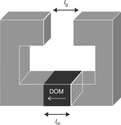
where μr is the relative recoil permeability of the second quadrant demagnetisation characteristic and typically takes values between 1.03 and 1.10 in the various rare-earth magnets.
As will be apparent from the nature of the above relationship, any increases in gap flux density achieved by increasing the length of the magnet (in the direction of magnetisation) are accrued with diminishing returns. This is illustrated in Fig. 19.27 which shows the proportion of the material remanence which can be achieved as gap flux density as a function of the ratio of the magnet length to airgap length. As will be apparent, the gap flux density only approaches asymptotically the permanent magnet remanence, irrespective of the ratio of the magnet length to airgap length. This illustrates a key driver of the quest for higher remanence, namely that limitations in remanence cannot be compensated for by simply incorporating more material into a device. Hence, there is a reasonably direct correlation between the remanence of a permanent magnet material and the performance of the device into which it is incorporated (for example, mechanical torque per unit of input current).
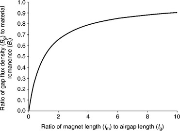
The relationship shown in Fig. 19.27 also illustrates that the gap flux density in a permanent magnet device is relatively insensitive to the length of the gap providing that the ratio of the magnet length to gap length exceeds a value of 5 or so. This is in marked contrast to magnetic circuits employing current-carrying coils to produce working gap flux, as in these types of devices the current required in a coil to maintain a given flux density is, at best, directly proportional to the length of the airgap. Hence, permanent magnet excitation offers very significant advantages in devices which necessarily require large airgaps because of factors such as the need to incorporate a fluid sealing sleeve in the airgap, or to accommodate some degree of relative movement between the rotor and stator.
Whereas the simple magnetic circuit in Fig. 19.26 results in one N and one S pole, many electromagnetic devices have many more individual poles arranged successively along the airgap. A major benefit of employing permanent magnets in electromagnetic devices when compared to current-carrying coils is their effectiveness in producing such high pole number fields, for example around the periphery of the airgap in an electrical machine. To a reasonable first approximation, there is little penalty in the volume of permanent magnet required to achieve a given gap flux density as the number of poles is increased (in practice, inter-polar leakage begins to play a role as the width of the poles approach the length of the airgap). In contrast, for a magnetic field produced by a series of current-carrying coils, considerable penalties are incurred with increasing pole number. This stems from the fact that, as the cross-sectional area of the magnetic pole decreases, the magneto motive force which must be produced by the coil at each pole to retain a given flux density, remains essentially constant. Maintaining this fixed product of the number of turns and current as the space available at each pole diminishes becomes increasingly problematic from the points of view of efficiency and temperature rise. This tends to impose an upper limit on the number of poles that can be produced by a machine which is reliant on current excitation.
Although using permanent magnets to generate the excitation flux in electrical machines has many advantages in terms of efficiency and power density, the essentially fixed nature of the flux produced by a magnet can be a drawback. In some applications, it is necessary to continually and precisely adjust the magnitude of the excitation flux in response to some control input. By way of example, in generators which are directly connected to the main electrical grid or an aircraft power supply (i.e., not via power electronic converters) it is necessary to adjust the magnitude of the flux to maintain a prescribed system voltage when either the generator speed or the load vary. For such applications, current-carrying coils are used as the source of excitation flux.
19.6 Applications of permanent magnet materials
19.6.1 Applications of permanent magnet materials in electrical machines
The emergence of rare-earth magnets resulted in a step-change in the performance that could be achieved with electrical machines equipped with permanent magnets, particularly in terms of power density. For a true like-for-like comparison, there is little contention that machines with rare-earth permanent magnets offer the highest levels of efficiency and compactness when compared with competing machine technologies such as induction, reluctance and wound-field motors, particularly in the power range up to 1MW. As a consequence, they have become widely used in applications which can accommodate some cost premium in return for enhanced performance, for example, servo-motors for high-performance industrial machinery, drives for hybrid-electric and all-electric vehicles and high-speed generators.
It is interesting to note that the commercialisation and widespread availability of rare-earth magnets are not the sole reasons why the use of highperformance permanent magnet machines has grown so dramatically in the last 20 years or so. Arguably, the great strides which have been made, and indeed continue to be made, in the performance of power electronic converters have been of at least equal importance, as this allowed the development of electronically commutated machines, otherwise known as brushless machines. Indeed, the vast majority of electrical machines equipped with rare-earth magnets are ‘brushless’ permanent magnet machines. This said, permanent magnet brushed machines with mechanical commutators (most commonly with ceramic ferrite magnets) remain a very important class of machine, and are widely used in many market sectors as a low-cost means of providing readily controllable torque or speed.
19.6.2 Applications in renewable energy
Brushless permanent magnets have traditionally been employed in small-to medium-sized electrical machines - that is, those with ratings up to several tens of kW and in some niche applications with ratings of 100s of kW. However, of late, permanent magnet machines have attracted considerable commercial interest as multi-MW level ‘direct-drive’ generators for off-shore wind turbines. Such generators are directly connected to the low-speed turbine rather than the more established configuration which employs an intermediate gearbox to drive the electrical generator at high speed.
Direct-drive generators for very large wind turbines - that is, those with ratings of 5 MW and above - typically rotate at speeds of only 10 rpm or so with torques in the MNm range. It is a reasonable truism that electrical machines of all types tend to be sized predominantly on the basis of their torque rating rather than power rating per se. Hence, the traditional approach of using a gearbox to increase the shaft speed, for example to 1500 rpm for 50 Hz grid connection of a four-pole machine, tends to yield significant dividends in the size of the electrical generator, in most cases more than offsetting the weight of the gearbox. However, direct-drive machines greatly simplify the drive-train of a wind turbine with claims of a 50% reduction in the number of parts. This leads to a strong case that direct-drive configurations enhance in-service reliability and reduce maintenance, which are important factors in the operating costs of offshore wind turbines.
Permanent magnet machines, often with many hundreds of poles on the rotors, are emerging as the preferred technology for multi-MW direct-drive generators.25 They offer significant advantages in compactness and efficiency, particularly at part-load. The compactness is largely derived from the ability of permanent magnet excitation to produce very high pole number fields, often many hundreds of poles, with little penalty in magnet volume or airgap flux density. Such high pole numbers allow significant savings to be made in the cross-section of the rotor and stator core backs required to carry the flux produced by a given pole-pair, and hence the active components (i.e., rotor core, rotor magnet, stator core and stator winding) tend to occupy a thin annulus centred on the working airgap. A typical predicted magnetic field distribution over one pole pair of a large direct-drive permanent magnet generator is shown in Fig. 19.28. This specific example has an airgap diameter of 4.0 m and 400 magnet poles. The active elements of the machine are contained within a relatively narrow annulus - the inner diameter of the rotor core is 3.96 m and the overall stator core diameter is 4.10 m.
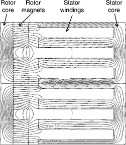
19.28 Finite element predicted magnetic field distribution over one pole pair of a 400 pole direct-drive permanent magnet generator.
A typical configuration of a large wind turbine equipped with a direct-drive permanent magnet generator is shown in Fig. 19.29. This particular example is a 2.3 MW turbine in which the direct-drive generator has an external permanent magnet rotor. These generators are connected to the main 50 Hz AC power grid via a power electronic converter which converts the variable magnitude and frequency of the generator output voltage to the fixed magnitude and frequency required by the grid.
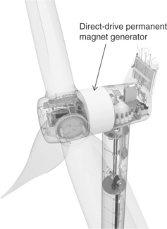
19.29 Typical configuration of a 2.3 MW wind turbine with a direct-drive permanent magnet generator - Siemens SWT-2.3–113.
There are permanent magnet direct-drive generator machines with ratings of 3 MW and above entering service in the mainstream offshore wind market. These behemoths of electrical machines, which have working airgap diameters of up 5 m or so and total weight of some 75 tonnes, are gaining significant market share with the expansion of offshore wind farms. Turbines with ratings up to 6 MW and 120 m blade diameters have been demonstrated and are likely to form the next generation of offshore wind turbines. Direct-drive turbines in these multi-MW power ranges incorporate many tonnes of sintered Nd2Fe14B permanent magnets in a single generator. Published design studies suggest that 3 MW direct-drive generators require some 2500 kg of permanent magnets per generator. The expected growth of these markets, particularly in China, will have profound resource implications.
Tidal-stream turbines also offer growing potential for the use of permanent magnet machines, although their deployment into service in meaningful numbers and MW ratings is some way behind wind turbines. As with offshore wind turbines, maintenance and repair are critical factors in the lifetime cost of the electricity produced by a tidal turbine. Indeed, accessing a tidal turbine for maintenance is arguably even more problematic and expensive. Hence, permanent magnet direct-drive generators are an attractive potential solution. Moreover, the great degree of flexibility in topology and geometry of permanent magnets machines allows them to be more readily integrated into novel concepts than competing machine technologies such as induction and wound-field generators. By way of example, they can be incorporated into a thin annulus within a ducted turbine.
19.6.3 Applications in electric and hybrid electric vehicles
Another rapidly moving field of technology which is increasingly drawing on high-performance electrical machines relates to all-electric and hybrid electric vehicles.26 In almost all demonstrator vehicles and mainstream product launches to date, the electric machines providing traction to the vehicles are brushless permanent magnet machines with rareearth magnets. A comprehensive review of permanent magnet brushless machines for hybrid and all-electric vehicles is provided in Reference 27. These machines are able to provide very high efficiency (> 95% being commonplace) over a wide speed and torque range. Indeed, as well as having outstanding headline single-valued efficiencies compared to those of competing machine technologies, permanent magnet machines tend to retain this high efficiency over a much wider range of operating conditions.28
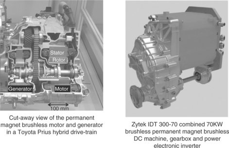
Permanent magnet brushless machines are capable of providing very high power densities even in high-volume cost-sensitive products. By way of example, the 50 kW (400 nm at 1200 rpm) NdFeB brushless permanent magnet motor employed in the Toyota Prius model launched in 2004 achieved continuous power ratings of 1.4 kW/kg.29,30 This motor is equipped with ~1.8 kg of sintered NdFeB magnets.
In applications which can tolerate a significant cost premium in order to meet very demanding targets on power density, such as aerospace and motorsport, the use of high performance Co-Fe stator and rotor core materials in combination with advanced liquid cooling can result in power densities of the order of 10 kW/kg.
Brushless permanent magnet machines offer considerable flexibility in terms of topology, geometry and aspect ratio which in turn provides many options for integration with other vehicle systems. By way of examples, in hybrid and all-electric vehicles, they have been deployed as thin annular section machines fitted around the engine flywheel to provide starting and torque boost facilities,31 as conventional internal rotor machines mounted in-board and driving through an otherwise conventional drive-train, and an external rotor machines within wheel hubs. Two examples of advanced drive-train which are based on permanent magnet brushless machines are shown in Fig. 19.30. In both cases, the electrical machine is highly integrated with system components.
19.7 References
1. Coey, J.M.D., Magnetism and Magnetic Materials. Cambridge University Press; 2011. 9780521816144.
2. Cullity, B.D., Graham, C.D., Introduction to Magnetic Materials. John Wiley; 2009. 0470386312.
3. Luo, Y. Proceedings of the 20th Workshop on Rare Earth Magnets and Their Applications, 2008:27.
4. Strnat, K.J., Hofer, G., Olsen, J.C., Ostertag, W., Becker, J.J. J. Appl. Phys.. 1967; 38:1001.
5. Goll, D., Kronmuller, H. Proceedings of the 21st Workshop on Rare Earth Magnets and their Applications, 2010:64.
6. Gutfleisch, O., Willard, M.A., Bruck, E., Chen, C.H., Sankar, S.G., Ping Liu, J. Adv. Mater. 2011; 23:21.
7. Liu, J.F., Hadjipanayis, G.C. J. Magnetism Magnetic Mater.. 1999; 202:69.
8. Hadjipanayas, G.C., Tang, W., Zhang, Y., Chui, S.T., Liu, J.E., Chen, C., Kronmuller, H. IEEE. Trans Magn.. 2000; 36:3382.
9. Sagawa, M., Fujimura, S., Togowa, M., Yamamoto, H., Matsura, Y. J. Appl. Phys.. 1984; 55:2088.
10. Croat, J.J., Herbst, J.F., Lee, R.W., Pinkerton, F.E. J. Appl. Phys. 1984; 55:2078.
11. McGuiness, P.J., Harris, I.R., Rozendaal, E., Ormerod, J., Ward, M. J. Mater. Sci.. 1986; 21:4107.
12. H. Nagel and I.R. Harris. CEAM Value Report, SC141/91-UK MAGPRO-1 (1994)
13. Harris, I.R., Williams, A.J.Harris I.R., Jones I.P., eds. GrainBoundaries:Their Character, Characterisation and Influence on Properties. IoM Communications Ltd:, 2001:165.
14. Santos, C.A., Spim, J.A., Jr., Garcia, A. J. Mater. Process. Technol.. 2000; 102:33.
15. Pei, W., He, C., Lian, F., Zhou, G., Yang, H. J. Magn. Magn. Mater. 2002; 239:475.
16. Sagawa, M. Proceedings of the 21st Workshop on Rare Earth Magnets and Their Applications, 2010:183.
17. Zakotnik, M., Harris, I.R., Williams, A.J. J. Alloys Compds. 2008; 450:525.
18. Mottram, R.S., Kianvash, A., Harris, I.R. J. Alloys Compds. 1999; 283:282.
19. Sugimoto, S. Proceedings of the 21st Workshop on Rare Earth Magnets and Their Applications, 2010:103.
20. Betancourt, I., Davies, H.A. Mater. Sci. Tech.. 2010; 26:5.
21. Book, D., Harris, I.R. J. Alloys Compds. 1995; 221(1-2):187.
22. Takeshita, T., Nakayama, K. Proceedings of the 11th Workshop on Rare Earth Magnets and Their Applications, 1990:29.
23. Honkura, Y. Proceedings of the 19th Workshop on Rare Earth Magnets and Their Applications, 2006:231.
24. Walton, A., Yi, H., Mann, V.S.J., Speight, J.D., Harris, I.R., Williams, A.J. Proceedings of the 22nd International Workshop on Rare Earth Magnets and Their Applications, 2012. [Nagasaki, Japan].
25. D. Bang, H. Polinder, G. Shrestha, J.A. Ferreira, ‘Review of Generator Systems for Direct-Drive Wind Turbines’, EWEC conference, Brussels (2008)
26. Momoh, O.D., Omoigui, M.O., An Overview of Hybrid Electric Vehicle Technology. Proceedings of IEEE Vehicle Power and Propulsion Conference, 2009 (VPPC ‘09), 2009:1286–1292.
27. Chau, K.T., Chan, C.C., Liu, C. IEEE Trans. Ind. Electron. 2008; 55:2246.
28. Zhu, Z.Q., Howe, D. Electrical Machines and Drives for Electric, Hybrid, and Fuel Cell Vehicles. Proc. IEEE. 2007; 95(4):746–765.
29. Ayers, C.W., Hsu, J.S., Marlino, L.D., Miller, C.W., Ott, G.W., Jr., Oland, C.B. Evaluation of 2004 Toyota Prius Hybrid Electric Drive System Interim Report. Oak Ridge National Laboratory Report ORNL/TM-2004/247. 2004.
30. J.S. Hsu, C.W. Ayers, C.L. Coomer, ‘Report on Toyota Prius Motor Design and Manufacturing’, Oak Ridge National Laboratory Report ORNL/TM-2004/137.
31. Wang, J., Taylor, B., Sun, Z., Howe, D. Experimental Characterization of a Supercapacitor-Based Electrical Torque-Boost System for Downsized ICE Vehicles. IEEE Transactions on Vehicular Technology. 2007; 56(6):3674–3681.