
Rapid, low-temperature processing of dye-sensitized solar cells
Abstract:
Dye-sensitized solar cells (DSCs) can be described as a form of artificial photosynthesis because light is captured in a similar manner by a chromophore. However, whilst in photosynthesis the solar energy is captured as chemical energy in bio-molecules, electricity is the product for DSCs making this an example of photovoltaic (PV) technology. One key advantage of DSCs compared to vacuum-processed, p-n junction PV technologies is the potential for it to be manufactured at a very large scale because DSC raw materials are readily available and the technology lends itself to roll-to-roll continuous processing. This chapter describes some of the existing issues associated with manufacturing DSC devices along with some of the remaining challenges to achieve the goal of very large-scale PV development.
3.1 Introduction to dye-sensitized solar cells (DSCs)
In the face of continuing increases in concentrations of infrared-absorbing gases in the atmosphere, the development of large-scale, low-carbon energy generation represents one of the sternest technological challenges facing humankind. At the same time, photosynthesis harvests sufficient solar energy to fuel the planet’s biosphere. In this context, photosynthesis can be considered to be a carbon-neutral and low-cost form of solar cell on an enormous scale. Hence, it is logical that one potential energy generation solution is the development of large-scale, low-cost artificial photosynthesis.
DSCs can be considered as a form of artificial photosynthesis because, in a similar way to photosynthesis, a chromophore harvests photons of solar energy. However, whilst in photosynthesis this energy is captured as chemical energy in the form of photosynthetic by-products such as carbohydrates, in DSCs, electricity is the end product. This is convenient because, once produced, electricity is a readily usable form of energy.
O’Regan and Grätzel (1991) wrote the seminal paper on DSCs in 1991 describing the use of a Ru-bipy complex (N3) as a sensitizing dye along with pre-made titania nanoparticles sintered together to create a photoelectrode with a vastly increased surface area. The advantage here was that this allowed for much more dye within the photo-electrode giving big increases in photocurrent and efficiency. In the ensuing 20 years since this report, thousands of academic papers and hundreds of patents have been published related to DSCs and a number of excellent reviews have been produced (Kalyanasundaram and Grätzel, 1998; Hagfeldt et al., 2010; Rhee et al., 2011). However, the key to realizing the commercial and environmental benefits of DSC is the large manufacturing scale-up of this technology and some of the challenges associated with this are the subject of this chapter.
3.1.1 Advantages of DSCs
DSCs can come in every shape, size and colour (Mishra et al., 2009). The reasons for this are that DSC electrodes can be printed onto the device substrates using a range of techniques to give almost any two-dimensional shape, individual DSC cells can be linked together to make modules across a range of length scales and a wide range of differently coloured dyes can be used to capture sunlight across the visible spectrum. DSC technology also benefits from the fact that the individual components of these devices are either relatively low cost and/or are used in very small quantities (Hara and Arakawa, 2003). DSC devices can also be manufactured using relatively low cost procedures using a wide range of substrates ranging from rigid glass to flexible metal foils and plastic offering the potential for continuous, automated processing (Hinsch et al., 2001). Hence, DSC technology offers real potential for the large-scale manufacture of lower cost solar cell devices to help to meet global low carbon energy generation targets. This chapter considers some of the technological challenges which remain to take DSC technology from the laboratory to large-scale manufacture and application.
DSC devices also offer a wide range of potential end uses for both indoor and outdoor applications. This is because, in addition to the advantages listed earlier, DSC devices operate well at a wide range of light levels and different angles of illumination (Yan et al., 2011). This is largely because, in DSC, photons are captured by an electron in a dye being raised to an excited state followed by injection of that electron into the conduction band of a titania nanoparticle (Halme et al., 2010). The electrons then pass between titania particles to the working electrode. In practice, this means that relatively rapid electron excitation and injection steps effectively represent charge separation, and any potential recombination processes or series resistance issues tend to take place during the electron’s passage from partiele to partiele, around the circuit and then back to the dye via an electrolyte redox couple. This means that any recombination processes tend to be less affected by incident light levels when compared to Si or thin-film PV (Halme et al., 2010). In addition, because DSC photo-electrodes consist of sintered metal oxide nanoparticles (usually anatase titania), incoming photons are routinely scattered within the device, which also means that the incident angle of light is relatively less important (Yan et al., 2011). Indeed, larger metal oxide scattering particles (circa 300 nm) can be added to the photo-electrode specifically to increase light scattering in order to increase photocurrents (Yan et al., 2011). Alternatively, smaller metal oxide particles can be used which can lead to almost transparent devices (Lin et al., 2010). This lends itself to building-integrated photovoltaics (BIPV) where semi-transparent solar cells available in a wide range of colours, which can double as windows, offer a particularly attractive combination (Yoon et al., 2011).
3.2 Manufacturing issues
DSC devices operate by the visible part of the solar spectrum being absorbed by dye molecules which are chemisorbed onto the surface of a metal oxide semiconductor (usually TiO2) (Kalyanasundaram, 2010). The resulting excited electrons are injected into the conduction band of the TiO2 before travelling through the TiO2 film to a working electrode, around a circuit to a counter electrode and back to the dye usually via an iodine-based redox couple in a liquid electrolyte. Figure 3.1 shows the desired electronic processes for efficient DSC operation which all move in a clockwise manner. Broadly speaking, any processes which move anticlockwise are undesirable recombination steps which result in efficiency losses and hence need to be minimized.
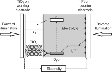
3.1 Schematic of a dye-sensitized solar cell showing reverse and normal illumination. The desired electron path is shown by the dotted arrows.
Figure 3.2 shows the relative energy levels associated with DSC operation, emphasizing the need to tune the dye HOMO and LUMO levels with the conduction band of TiO2 and the electrolyte redox couple in order to optimize device efficiency.
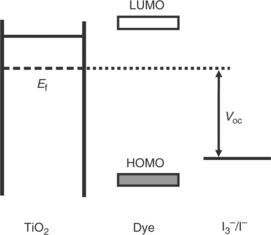
3.2 Key energy levels of a dye-sensitized solar cell showing TiO2 Fermi level, dye HOMO and LUMO, redox couple and resultant Voc.
In the laboratory, DSC devices are usually made using a batch-scale process where the two electrodes are handled separately and then sealed together as one of the final steps in the overall process. For a typical laboratory-manufactured glass-based device, a colloid containing a binder such as ethyl cellulose is mixed with crystalline particles of anatase TiO2 which are circa 20 nm in diameter and printed onto a TCO-glass sub-strate to produce a film which is circa 25–50 μm thick (Hara and Arakawa, 2003). This is allowed to dry before sintering by heating to between 450 and 550°C for ≥ 30 min to produce a nanoporous thin-film of TiO2 particles with a high internal surface area. This TiO2 photo-electrode is usually then immersed in a solution of TiCl4 and re-sintered at between 450 and 550°C for another 30 min (Sommeling et al., 2006; O’Regan et al., 2007). The TiO2 film is then ready for sensitization which typically takes place by immersion in a dye solution overnight to ensure maximal uptake of a mono-layer of dye on the TiO2 surface (Ito, 2010). At this point, the working or photo-electrode is ready (Fig. 3.3). For the counter electrode, a catalyst is required at the surface to speed up the transfer of electrons to the I−/I3− redox couple because otherwise this process is too slowwhich seriously limits device performance. To date, the most efficient catalyst is platinum (Murakami and Grätzel, 2008). Usually the Pt catalyst is applied to the counter electrode by spreading a Pt precursor solution (usually H2PtCl6) to a TCO–glass substrate followed by thermal decomposition by sintering at 400°C (Murakami and Grätzel, 2008). The working and counter electrodes are then sealed together usually by heating an appropriately sized thermo-plastic gasket around the photo-electrode and the resulting void filled with electrolyte solution.
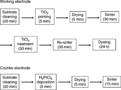
Taking these process steps sequentially, for the working electrode this gives a total of at least six steps with a total processing time of at least 24 h and a maximum processing temperature of circa 500°C. The corresponding values for the counter electrode are at least four steps taking at least 45 min with temperatures up to circa 400°C. To commercialize DSC on a large scale, there is a need to reduce the number of processing steps and also to make them compatible with continuous processing (i.e., to move away from batch processing). This impacts significantly on the time that each process step can take. In addition, the processing temperatures described previously also limit the possible substrates to glass as a transparent window material and certain metals where an opaque substrate can be used as an electrode. This sets a technological paradox; it is necessary to develop processes which can take place significantly faster (ideally in minutes) at significantly lower temperatures (ideally several hundred °C lower) when it is well known that the vast majority of chemical reactions happen more slowly at lower temperatures. At the same time, for DSC technology to be commercially competitive, it is necessary to maintain or ideally to improve device efficiencies and ensure device longevity.
3.3 Sensitization
Since 1991, literally thousands of dyes have been synthesized and trialled in DSC devices and these dyes have been the subject of detailed reviews (Agrazzi et al., 2004; Robertson, 2006; Mishra et al., 2009; Clifford et al., 2011). For many years, ruthenium complexes have dominated DSC dyes and this family of dyes still hold the world record device efficiencies for DSC with η > 10% for Ru-bipyridyl complexes such as N719 (Nazeeruddin et al., 2005), ‘black dye’ (Nazeeruddin et al., 1997) or C101 (Cao et al., 2009). In more recent years, there have been increasing reports of metal-free or organic dyes which are also capable of achieving high device efficiencies. Many of these dyes absorb in a similar part of the solar spectrum to the Ru complexes (λmax ~ 550 nm) where the solar intensity is at its highest (Fig. 3.4). Broadly, these dye families can be described as coumarins (Hara et al., 2003; 2005), indolines (Horiuchi et al., 2003; Ito et al., 2006) and triarylamines (Hwang et al., 2007; Gang, 2009; Zhang et al., 2009; Im et al., 2010). However, there is increasing interest in dyes which can absorb photons at longer wavelengths (i.e., into the NIR region) such as phthalocyanines (Yum et al., 2008; Bessho et al., 2010; Mori et al., 2010; Garcia-Iglesias et al., 2011), squaraines (Yum et al., 2007; Geiger et al., 2009; Bagnis et al., 2010; Choi et al., 2010; Shi et al., 2011) and cyanines (Ono et al., 2009; Funabiki et al., 2011).
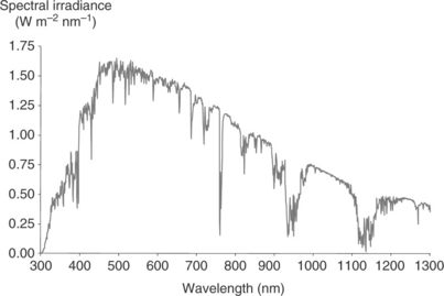
3.4 The AM1.5 solar spectrum (www.nrel.com).
Closely linked to research into dyes which absorb in different parts of the solar spectrum is the concept of dyeing photo-electrodes with more than one dye. This concept can be described as ‘cocktail’ dyeing, multiple dyeing or co-sensitization. The overarching aim of this concept is to harvest photons from different parts of the solar spectrum using different dyes rather than to synthesize a single dye with a very broad absorption. To date, attempts at co-sensitization have depended on rather long-winded processes (Cid et al., 2007; Kuang et al., 2007; Inakazu et al., 2008; Ogura et al., 2009) and reports of successful co-sensitization have been fairly limited (Chen et al., 2005; Cid et al., 2007; Kuang et al., 2007; Inakazu et al., 2008; Lee et al., 2009; Ogura et al., 2009) which may be due to the difficulties which can be experienced when carrying out co-dyeing of TiO2 photo-electrodes. Thus, simply immersing TiO2 in a mixed dye solution rarely produces devices which are superior to those sensitized with a single dye. This is presumably due to the difficulties of controlling dye uptake in a passive dyeing situation with the dyes simply allowed to compete for surface sites. However, with the use of a new ultra-fast dyeing technique developed in our laboratory at Bangor (Holliman et al., 2010), we have been able to much more readily control dye uptake which has enabled us to successfully co-sensitize with a range of different dyes.
3.3.1 Dye sensitization
As stated previously, the sensitization of the TiO2 photo-electrode relies on a ‘clean’ metal oxide surface where all residual organic matter has been removed, most usually by heating. Dyeing takes place by immersing the photo-electrode in a dye solution. Given the importance of dye sensitization to DSC performance, there have been surprisingly few reports on this subject. Equally, there have been very few literature studies which have looked at speeding up the dye sensitization process when it is clear that immersion in large volumes of valuable and potentially sensitive dye solution for hours at a time is not practical for any large-scale manufacturing process. Indeed, the immersion procedure is dominated by passive diffusion of dye solution through the photo-electrode and so relies on extended immersion periods (Ito, 2010) such that this method is most accurately described as ‘passive’ dyeing. Gratzel et al. has reported a rapid dipping process for sensitization which takes 10 min (Nazeeruddin et al., 2003) and Hincsh et al. and then Sommeling et al. reported refluxing dye solution through the cavity of DSC devices for 30–60vmin (Hinsch et al., 2001; Sommeling, 2004).
For DSC scale-up, each manufacturing step must be rapid and as straightforward as possible. In this context, ultra-fast sensitization can now be achieved in 5 min by first sealing the working and counter electrodes (Fig. 3.5) and then pumping dye solution through the resulting cavity (Holliman et al., 2010). Because the volume of dye solution (1–2 mL) is huge compared to the cavity (10–50 μL), the turnover of dye solution within the cavity is very fast, which overcomes the limitations of passive dyeing and brings the dye solution into contact with the entire photo- electrode at the same time. The rate of sensitization is then controlled by the rate of adsorption (which is rapid) compared to diffusion through the photo-electrode (which is relatively slow). The ultra-fast sensitization technique works well for the Ru dye N719 and actually improves device efficiency for the squaraine dye SQ1 (Holliman et al., 2010). The latter improvement is ascribed to protection of the dye from atmospheric exposure within the device cavity.
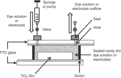
3.5 Design of the dye-sensitized solar cell used for ultra-fast sensitization. (Source: Holliman et al., 2010. Reproduced by permission of The Royal Society of Chemistry.)
Another significant benefit of ultra-fast dyeing is that it can also be used to co-sensitize TiO2 films in 5 min or less. To date, this has been reported for N719 and SQ1 (Holliman et al., 2010) although more recent data in our laboratory suggest that this approach can also be successful for other dye combinations as well (Holliman et al., 2012). In all these examples, the definition of successful co-sensitization is that device efficiency is greater with two dyes than with either of the single dyes on their own. As might be expected, the main advantage for co-sensitized devices is an increase in short-circuit current which is in line with the capture of more photons leading to more excited electrons. By comparison, changes in the open circuit voltage vary depending on the dye combination used, with some examples giving slightly increased Voc which is ascribed to reduced recombination (Holliman et al., 2010) whilst reductions in Voc may reflect slightly mismatched dye HOMO and LUMO energy levels. Fill factors for co-sensitized DSC devices generally tend to decrease because the series resistance of currently available DSC devices generally tends to limit the benefit of increased current except for very small devices. Overall, ultrafast co-sensitization is a key technology in the scale-up of DSC because it is significantly faster, more controllable, uses less dye solution and gives rise to more efficient DSC devices.
3.4 Electrodes
3.4.1 Substrates
As discussed previously, DSC devices consist of two electrodes sandwiched around an electrolyte; the working or photo-electrode has a dye-sensitized metal oxide attached and the counter electrode usually has a thin Pt coating. Hence, in theory, DSC devices can be prepared on any conducting substrate as long as one of the electrode substrates is sufficiently transparent to enable photons to enter the device.
Most commonly, DSC devices are prepared using two glass substrates, because transparent conducting oxide (TCO)-coated glass can readily be sourced with a variety of conductivities, these substrates are thermally stable well above the upper end of typical sintering temperatures (500°C), and glass is chemically resistant and impervious to typical DSC electrolytes (Kao et al., 2011). Using two glass electrodes also enables the device to be illuminated either through the photo-electrode which is known as ‘normal’ illumination or through the counter electrode which is known as ‘reverse’ illumination (Fig. 3.1); the former is preferable as this avoids any photon losses which occur by light passing through the most widely used iodide/triiodide electrolyte (Lin et al., 2011).
Other potential substrates include metal foils and plastic films which both have the advantage of being more flexible and lightweight than glass. Metal films also offer much better lateral conductivity than TCO-coated glass or plastic (Vijayakumar et al., 2011) but at the expense of transparency which means that, currently, metal-based DSC devices are normally operated under reverse illumination which reduces their efficiency compared to glass devices (Park et al., 2008). Some metal films are also not stable to the electrolyte in the longer term (Reynolds et al., 2010). In reality, TCO-coated plastic films are restricted to indium tin oxide (ITO) coatings which are most widely available on polyethylene terephthalate (PET) or polyethylene napthalate (PEN) films at conductivities ranging from 15 to 1000 ohms per square (Chen et al., 2010a). The downside of these polymer films is their thermal stability, which limits processing temperatures to < 150°C (Yamaguchi et al., 2010) and their cost because the ITO is typically coated onto the plastic using vacuum-based processing (Herrero and Guillén, 2002).
3.4.2 Working electrode and titania sintering
During the fabrication of DSC devices, the metal oxide photo-electrodes are prepared from a paste or colloid of metal oxide nanoparticles (most typically TiO2 nanoparticles) which are mixed with a solvent and an organic polymeric binder (Ito, 2010). This mixture forms a viscous paste which can be printed onto a conducting substrate to form a thin porous film to form the photo-electrode. However, this photo-electrode film is then usually heated (or sintered) which serves the combined purposes of evaporating the solvent, combusting the binder and sintering the titania particles together to improve their connectivity, mechanical strength and the electrical conductivity of the photo-electrode (Ito, 2010). Sintering also prepares the metal oxide surface for dye sensitization such that insufficient sintering leads to poor dye uptake, low photo-current and sub-optimal device performance.
In general, sintering is usually carried out at between 450°C and 600°C which limits the substrates which can be used to TCO-coated glass or metal foil. Reports have centred on studying the effects of different sintering processes, metal oxide particles (Barbé et al., 1997; Chen et al., 2009, 2010b; Lee et al., 2009; Sauvage et al., 2010) and photo-electrode designs (e.g., film thickness and the design of the active area) (Wang et al., 2004; Park et al., 2007; Kao et al., 2009). Research has also been carried out looking at pre- and post-sintering treatments of the photo-electrode (Fabregat-Santiago et al., 2004; Sommeling et al., 2006; O’Regan et al., 2007). The most widely use post-treatment is a solution of TiCl4 (O’Regan et al., 2007). The precise mode of operation of this post-treatment has been the subject of much debate; it has been reported to shift the conduction band of TiO2, improve dye uptake and particle interconnectivity leading to enhanced conductivity (Sommeling et al., 2006). The reality is perhaps more straightforward in that the use of TiCl4 reduces the variance in device performance which can occur between TiO2 photo-electrodes which have been printed and sintered under apparently identical conditions. In effect, it can improve photo-electrodes which would otherwise perform poorly and bring all photo-electrodes closer together in terms of their performance.
In order to extend the range of substrates which can be used in DSC devices, it is necessary to significantly reduce the sintering temperatures from 450°C. In this context, two reduced temperature ranges can be considered; low-temperature sintering at ≤ 300°C and ultra-low-temperature sintering at ≤ 150°C. The potential approaches to achieve sintering at lower temperatures often include removal of the binder (this is usually a long-chain organic polymer) from the titania paste which eliminates the need to remove this material during sintering (Park et al., 2005). As this process is usually achieved by combustion, this significantly reduces the temperatures required during sintering. However, because the binder is added to help control the viscosity of the TiO2 paste, removing it makes it more difficult to control the printing of the photo-electrode films. Examples of the chemical sintering agents used include titanium alkoxides (Zhang et al., 2006; Li et al., 2008), other soluble titanium compounds (Gutiérrez-Tauste et al., 2005) or other compounds such as silicon-based precursors (Du Pasquier et al., 2009) or hydrochloric acid (Weerasinghe et al., 2010).
A second approach is the use of chemical sintering agents which are soluble and which can coat the surfaces of the TiO2 particles and then decompose at low temperature (usually by hydrolysis) to form a metal oxide which can ‘glue’ the particles together. Other methods which have been reported include the use of alternative means of introducing energy into the sintering process than conventional heat, for example UV (Murakami et al., 2004; Gutiérrez-Tauste et al., 2005) or NIR (Watson et al., 2010) or the use of hydro- thermal treatment (Zhang et al., 2002) or pressure sintering (Yamaguchi et al., 2007, 2010); the latter avoiding the need for heating at all. However, to date these methods have not crossed into large-scale manufacture because of the difficulties of reproducing them at scale. One reason for this is that the chemical sintering agents have to be liable to hydrolysis which could cause problems in the consistent application of these compounds on a production line. For the pressure sintering, the long-term mechanical performance of such devices may be a cause for concern because the inter-particle connections of the TiO2 particles do not arise from the type of chemical bonds which arise either from sintering at temperature with time or with the ‘ceramic glue’ approach of chemical sintering. Instead, the particles are simply pressed together which leaves the potential for them to relax back to their original position to a greater or lesser extent with an associated loss of mechanical and electrical performance of the photo-electrode.
The other electrode in a DSC device is the counter electrode (Fig. 3.1). The main function of this electrode is to return electrons to the electrolyte redox couple. For high-efficiency DSC devices, the most commonly used redox couple is I3−/I−. However, electron transfer to this redox couple is slow unless a catalyst is present. To date, platinum has been the most widely used catalyst and is generally considered to be the most efficient (Hara and Arakawa, 2003) although metal sulfides (Wang et al., 2009; Dun et al., 2011) and carbonaceous- based materials and conducting polymers have also been used (Murakami and Grätzel, 2008). The topic of DSC counter electrodes has been the subject of two recent reviews (Papageorgiou, 2004; Murakami and Grätzel, 2008).
Regardless of the catalyst used, the requirements for the transparency and physical nature of this counter electrode are dependent on the direction of illumination of the device. Thus, if the light first passes through the TiO2 photo-electrode (i.e., normal illumination, Fig. 3.1) then the counter electrode can be opaque, meaning that the substrate can be any conducting material and the catalyst can be deposited in any form providing it adheres to the substrate and exhibits sufficient activity. Given the wide choice of substrates, this normally means that there are no limits to the processing temperature which can be used. However, if the device is operated in reverse illumination, the photons pass through the counter electrode before entering the device. This means that the counter electrode substrate and catalyst must be as transparent as possible to minimize photon losses. Typically, high transmission is achieved by depositing catalyst particles which are as small as possible to minimize light scattering onto a transparent conducting substrate. In this context, the most widely used substrates are either glass or a transparent polymer coated with a transparent conducting oxide such as fluorine-doped tin oxide (FTO) or indium tin oxide (ITO). Comparisons of various counter electrode substrates have been carried out looking at metals, polymers and glass substrates (Ma et al., 2004; Fang et al., 2005) and NiP-coated glass (Wang et al., 2005a).
Looking at platinum as the most widely used catalyst, thermal decomposition of an aqueous solution of [PtCl6]2− at 400°C is the standard method used for temperature resistant substrates (Cherepy et al., 1997; Ito, 2010). Depending on the substrate and the application process, this can produce a Pt deposit of variable thickness. The influence of Pt thickness on device performance has been studied showing that films ranging from 2 to 415 nm showed similar device efficiencies although counter electrode sheet resistance did decrease for thicker Pt layers as expected (Fang et al., 2004). However, for reverse illumination, photons must travel through the counter electrode and so transparency becomes a key limiting factor for device efficiency (Jun et al., 2007). Thus, two issues arise for DSC commercialization. Firstly, the development of an invisible layer of platinum which retains the desired catalytic activity for electron transfer, and secondly the need to deposit this layer rapidly at low temperature if TCO-polymer substrates are to be used. Taking transparency first, producing a Pt layer consisting of small particles has the advantage of increasing the effective surface area which means that a lower Pt loading can be used. As stated earlier, commercially available TCO-coated polymeric substrates are currently restricted to ITO coated onto either PEN or PET films which limits Pt processing temperatures to < 150°C. Low-temperature Pt deposition processes onto these types of substrates is most usually achieved either by sputtering, chemical or electrochemical reduction of a Pt precursor (Ma et al., 2004; Papageorgiou, 2004; Fang et al., 2005; Murakami and Grätzel 2008). Hexachloroplatinate is the most commonly used precursor because it is relatively stable in aqueous and organic solvents whilst also being readily reduced by a range of chemical agents – for example, sodium borohydride (Kang et al., 2006) and hydrogen (Khelashvili et al., 2007). Electrochemical reduction avoids the need for a chemical reducing agent but needs careful control of the electrical field to ensure consistent deposition (Papageorgiou, 2004; Murakami and Grätzel, 2008).
3.5 Electrolyte
3.5.1 Liquid electrolyte
As stated earlier, the function of the electrolyte redox couple is to carry charge from the counter electrode to the photo-electrode and to reduce the dye cation after electron injection. For liquid electrolytes, the redox couple most often employed is I−/I3 where the oxidized dye is reduced by I− which is in turn oxidized to I3−. The I3− ions must then diffuse towards the counter electrode to be reduced by electrons from the external circuit whilst the I− produced from this must diffuse back towards the photo-electrode in a cycle (Jiang and Yanagida, 2010). High I− concentrations ensure that regeneration of the oxidized dye competes kinetically with charge recombination from the TiO2 film (Wang et al., 2005b). Other redox couples include halides and pseudo-halides such as Br−/Br3− (Oskam et al., 2001), SCN−/(SCN)3− (Wang et al., 2004), and SeCN−/(SeCN)3− (Guo et al., 2011) and cobalt-based redox couples (Liu et al., 2011).
The other electrolyte components can also influence electrolyte performance, with surface-adsorbed I− counterions (e.g., H+, Li+, K+ or Mg2 +) known to alter the TiO2 conduction band energy. It has also been observed that adsorbed cations can enable faster dye regeneration, possibly by polarizing the TiO2 surface and attracting I− towards the TiO2/electrolyte interface (Pelet et al., 2000). Electrolyte viscosity also affects I−/I3− diffusion such that, for low-viscosity solvents such as acetonitrile, 0.3 M I− concentration is adequate whilst higher concentrations are required for viscous ionic liquids (Boschloo et al., 2009). Dipolar aprotic solvents are generally preferred, due to the electrochemical stability and the solubility of common electrolyte components within them. It has also been reported that the type of solvent can influence the flat band potential (Vfb) of the cell and therefore Voc (Jiang et al., 2010). Ionic liquids have also been studied as DSC electrolytes due to their chemical and thermal stability, negligible vapour pressure, non- flammability, high ionic conductivity and electrochemical stability (Ferrere et al., 1997). Ionic liquids include imidazolium derivatives such as 1-propyl- 3-methylimidazolium iodide (PMMI) which are widely used as electrolyte additives to improve device performance by increasing electrolyte conductivity (Bonhôte et al., 1996). Another common additive is tert-butylpyridine which increases Voc and fill factor by causing a negative shift of the TiO2 conduction band and by suppressing the dark current at the semiconductor- electrolyte interface (Nazeeruddin et al., 1993).
3.5.2 Gel electrolyte
A liquid electrolyte is the ideal medium for DSC devices to ensure efficient and continuous contact is maintained between the redox mediators and the dye to maintain charge transfer. However, the application of a liquid electrolyte to DSC devices in a roll-to-roll manufacturing process is non-trivial, and liquid components inevitably offer leakage and evaporation problems which can degrade device performance over time. One alternative to liquid electrolytes are quasi-solid-state electrolytes where a thermo-reversible gel electrolyte replaces the liquid phase (Kubo et al., 1998, 2001; Hagfeldt et al., 2010). This can be achieved by the addition of low molecular weight amino acid derivaties (Kubo et al., 1998), silicon nanoparticles (Wang et al., 2003) or polymers (Cao et al., 1995; Matsumoto et al., 2001). Typically, gelation does not affect electrolyte conductivity (Hanabusa et al., 1999) and similar device efficiencies to liquid electrolytes have been reported for the addition of low molecular weight organic gelators. The mode of charge transport in gelled systems is maintained as being a diffusion process with generally no additional other changes to the electrolyte components. Penetration of the gelled electrolyte into the mesoporous TiO2 photo-electrode structure is crucial. This is generally achieved by initially solubilizing the electrolyte components in a heated solvent followed by subsequent impregnation in the solution phase into the film and then gelation by cooling. Gelation of electrolytes to a quasi-solid-state has been shown for electrolytes using organic solvents and also ionic liquids (Murai et al., 2003).
3.5.3 Solid-state electrolytes
A further development to replace liquids in DSC devices is to move to solid-state electrolytes which should also enhance long-term stability. One of the earliest examples used a p-type semiconductor by solubilizing CuI in acetonitrile and immersing a TiO2 electrode in this solution (Tennakone et al., 1995). This gave reasonable efficiencies but suffered increased recombination affecting device performance (Perera and Tennakone, 2003). Hole transport mediums (HTM) have also been studied as an alternative to liquid electrolytes (Bach et al., 1998). Spiro-OMeTAD (2,2’7,7’-tetrakis (N, N-di-p-methoxyphenylamine)-9,9’-spirobifluorene) is the most popular HTM with electron transfer occurring by hole injection from the oxidized dye into the HTM. The electron is then transported through the TiO2 and the hole through the HTM to the counter electrode.
One current downside of solid electrolytes is that the TiO2 film thickness is limited due to difficulties in impregnation of the HTM into the porous TiO2 film and the surface pores on the individual TiO2 particles as well as increased rates of recombination (Fabregat-Santiago et al., 2009). Impregnation is generally achieved by spin coating a solution of HTM and then allowing the solvent to evaporate. For spiro-OMeTAD, it has been demonstrated that it is possible to completely infiltrate a 2.0 μm thick TiO2 film (Kroeze et al., 2006). However, pore filling in thicker films has been shown to be incomplete (Ding et al., 2009). A thinner TiO2 layer in solid-state DSC means less dye available for photo-excitation and this issue has driven the research into higher molar extinction coefficient dyes. To date, efficiencies for solid-state DSCs have been demonstrated up to 5% (Snaith et al., 2007).
In device processing terms, the application of solid-state electrolytes by spin coating or metal cathode evaporation do not lend themselves to upscaling particularly given the need for a vacuum and specific device architecture on flexible metal substrates. Doctor blading has been demonstrated for HTM based DSC showing efficiencies of 3% for 2.0 μm films (Ding et al., 2010) which hints at potential application in roll-to-roll processing. However, solid-state DSC devices do not yet have efficiencies as high as their liquid counterparts although the added processing and stability advantages suggest they are worthy of continued study.
3.6 Quality control (QC)/lifetime testing
3.6.1 In situ dye uptake monitoring
As described earlier, a key step in DSC manufacture is sensitization of the TiO2 surface. The recent report of ultra-fast dyeing in < 5 min (Holliman et al., 2010) has overcome the need for 24 h immersion of the photo-electrode in dye solution. Hence, rapid in situ measurements of dye uptake are key for the rapid up-scaling of DSC technology (Watson et al., 2011). These in situ measurements are designed to measure what happens in a TiO2 film during exposure to a dye solution such that initial exposure of the top surface of the film is accompanied by very rapid dye sorption in this part of the film. This is followed by gradual diffusion and percolation of the dye solution through the film to the TiO2–TCO interface with concomitant dye sorption through the film as the solution progresses. Thus, sensitization of a photo-electrode can be considered to be complete when TiO2 particles at the bottom of the film are saturated with dye molecules. Thus, imaging the underside layer of a photo-electrode (Fig. 3.6) can be used to follow the dye uptake process (Watson et al., 2011). In this method, digital image capture combined with image analysis to extract RGB (red-green-blue) colour data has shown suitability for in-line monitoring of dyeing. UV–Vis reflectance spectroscopy has also shown that well-resolved λ data can also be measured. Factors affecting dye uptake have been shown to include dye concentration, agitation, film thickness and temperature (Holliman et al., 2010; Watson et al., 2011). In the future, digital imaging offers the potential to take a more combinatorial approach to DSC dyeing such that multiple samples can be imaged simultaneously. In addition, UV–VIS measurements can consider differently coloured dyes which will become more important as co-sensitization (Holliman et al., 2010) becomes more widely used. In summary, these methods are more rapid than ex situ desorption of dye into alkaline media which also damages the photo-electrode, although this method remains useful for absolute measurements of dye loading (Holliman et al., 2008).
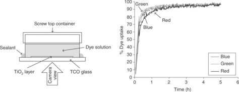
3.6 (Left) Time lapse dye uptake apparatus and (right) dye uptake plot for 0.3 mM N719 dye between 0% and 100% uptake showing red (R), green (G) and blue (B) colour data. Source: Watson et al., 2011. Reproduced by permission of The Royal Society of Chemistry.
3.6.2 Device stability and testing
Long-term device stability is an important issue for any photovoltaic technology in order to ensure that pay-back times are satisfied. For DSC devices, the cell architecture and components define the potential stability issues. Firstly, the photo-catalytic properties of TiO2 are well documented (Li et al., 1984; Mills et al., 1993; Wold, 1993) with photo-catalytic reactions resulting from electron–hole pairs caused by direct excitation of TiO2 by UV light (Ollis et al., 1989). In particular, radicals can degrade organic molecules in the vicinity of the TiO2 (Robinson et al., 2004). In a DSC device, this potentially means the adsorbed dye and/or the electrolyte. However, the hole in the TiO2 valence band is generally believed to be quenched by I− in the electrolyte, although possible side reactions with residual oxygen leading to attack on the dye surface groups have been reported (Hinsch et al., 2001).
Secondly, laboratory DSC devices are generally sealed using a thermoplastic gasket such as Surlyn or Bynel. The main issues here are the chemical and physical resistance of the seals to the electrolyte components and solvent evaporation, respectively. The transmission rates of H2O and O2 must also be low to prevent their ingress into the cell. For example, for longterm stability a water vapour transmission rate (WVTR) ≤ 10− 6 g/cm− 2/day is required. Effective long-term sealing protects device performance as there are many hypotheses regarding degradation of DSCs which involve the presence of water or oxygen (Asghar et al., 2010) including the oxidation of electrolyte from I3− to IO3− (Macht et al., 2002). Approaches to mitigate these problems include sealing using a glass frit (Sastrawan et al., 2006), the use of hydrophobic dyes such as Z907 to reduce water adsorption on the TiO2 surface which might break the dye–TiO2 ester linkages (Wang et al., 2003b; Kroon et al., 2007) and the development of water-stable dyes and aqueous electrolytes (Law et al., 2010).
For the sensitizing dye, Grätzel et al. have predicted that Ru sensitizers should be capable of 107–108 redox cycles for a predicted lifetime of 20 years (Kohle et al., 1997). Photocurrent mapping techniques have suggested that localized degradation can occur in unmasked parts of a partially masked cell when exposed to light soaking conditions (Barkschat et al., 2008). Elevated temperatures have also been linked to dye desorption (Hinsch et al., 2001; Sommeling et al., 2004) which is important for BIPV applications as roof temperatures in summer (even in temperate climates such as the UK) can reach 80°C.
Looking at the other half of a DSC device, counter electrode degradation has also been reported, suggesting that the catalytic Pt layer on the counter electrode can be prone to dissolution or anodic corrosion in the presence of I− (Papageorgiou, 2004). For the electrolyte, I3− depletion has been observed in DSC cells subjected to outdoor testing (Kato et al., 2009a). The mechanism of I3− loss has been suggested as either the sublimation of I2 (Matsui et al., 2009) or, as stated earlier, the formation of iodate (Macht et al., 2002). However, photoreactions have also been suggested with reports that electrolyte bleaching occurs rapidly in illuminated cells held at 85°C but not for cells held at 85°C in the dark (Sommeling et al., 2004). Accelerated UV exposure tests in our laboratory at Swansea suggest that I3− depletion is the dominant failure mechanism with UV exposed devices showing a near-total collapse in Jsc with a parallel increase in recombination resistance. Furthermore, our data show that devices degrade much faster when placed under an electrical load, suggesting that I3− may be consumed by reaction with photo-generated, oxidative TiO2 holes. The better news is that this issue can be easily avoided by simple UV filtering (Carnie et al., 2012a).
Over the past 10 years, some notable studies have been presented on DSC stability (Hinsch et al., 2001; Sommeling et al., 2004; Kato et al., 2009b) as well as a comprehensive review in 2010 (Asghar et al., 2010). However, less attention has been directed towards the photo-stability of polymer films intended for use as flexible substrates with the two most likely materials being polyethylene terephthalate (PET) and polyethylene napthalate (PEN). Both of these polymers are susceptible to UV photo-degradation, with PET by-products being quinones and diquinones (Edge et al., 1995) or 2-naphthanoic acid for PEN (Scheirs et al., 1997). These by-products result in film yellowing which can be monitored at λ = 400 nm. Whilst PET and PEN films can be stabilized by adding UV absorbers to the processing melt, this can be expensive. In our laboratory in Swansea, we have developed an accelerated UV test to measure CO2(g) from polymer film photo-degradation using FTIR spectroscopy (Robinson et al., 2004). Using this equipment and λ400 measurements, we have shown that both PET and PEN films can be stabilized by the application of a thin topcoat of an inexpensive, UV-stabilized, polyurethane clear-coat lacquer which has proven stability for over 7000 h QUV accelerated weathering on an 8 h UV to 4 h moisture cycle.
Although there can be optical losses associated with UV filtering, our data show that filtering DSC test cells with a UV cut-off at 385 nm does not significantly damage cell efficiency and, in some cases, the anti-reflection properties of the lacquers used can even slightly increase light transmission and cell efficiency (Carnie et al, 2012b).
3.7 Conclusions and future trends
In summary, the case for low-carbon energy production is very clear, with renewable energy targets set already in place in many countries. Delivering large-scale, low-carbon electricity is crucial to meeting these targets, and will most likely take place through a mixture of several technologies including photovoltaic devices. This means that the development of large-scale manufacturing for photovoltaic devices which can be produced at a commercially effective cost is essential. This needs to be achieved as soon as possible, both to be competitive with other technologies and to contribute to renewable energy targets as soon as possible. In reality, large-scale, low-cost solar cells will require continuous, automated processing rather than more labourintensive and slower batch style processing which is more typical of vacuumderived materials. The manufacture of DSC devices does not require vacuum processing. The requirements of DSC substrates are only that they should be conductive and that there must be one optical window to allow light to enter the device. This means that flexible substrates are suitable for DSC which, in turn, means that continuous, roll-to-roll processing is possible for DSC manufacture. In addition, most of the processing can be done using printing, which is compatible with roll-to-roll processing. Finally, as stated earlier, all the individual components of a DSC device are either low cost and/or are used in small quantities, making DSC devices a real possibility for large-scale manufacturing. The key manufacturing challenges are therefore to achieve all the individual processing steps fast enough so as not to slow down the overall speed of the production line but at low enough temperatures so as not to degrade any of the component materials. At the same time, the device efficiency must be increased to compete with other PV technologies and the resulting modules need to carry an extended lifetime guarantee.
In terms of the industrialization and scale-up of DSC technology, a number of companies around the world currently supply DSC products (for instance G24i in the UK, Solaronix in Switzerland and 3G Solar in Israel). Many more companies have development projects working either on sub-components of DSC and/or on up-scaling the manufacture of these devices. The long-term success of these ventures will be measured in commercial terms and DSC technology will need to compete with other forms of low-carbon energy in order to succeed on these terms. The most likely scenario is that many different renewable energy technologies will form a patchwork of energy supply including wind turbines, biomass and PV. However, some of the key advantages of PV are that energy is produced where it is needed and there is not the same requirement for building large power plants. Within the PV sector, there is also likely to be a range of technologies which will be successful for different end-uses. For the DSC, the potential lies in its low-cost components and large-scale manufacturability. When these factors are combined with the use of flexible and lightweight substrates, DSC technology offers commercial opportunities ranging from very large-scale BIPV to highly portable power generation for individuals on the move. However, the DSC is unlikely to compete in commercial terms with conventional silicon PV in the solar farm market in the equatorial region because of the efficiency benefits of Si under high solar intensity and high angle solar irradiation. In contrast, where the DSC shows benefits over other PV technologies is in more northerly and/ or southerly global regions where solar irradiation is lower, and impinges at lower angles and where DSC devices perform more consistently under the variations in solar intensity and angle throughout the day. In summary, DSC does not currently exhibit the same headline efficiencies for laboratory-scale devices under perpendicular, one Sun (AM1.5) solar irradiation. However, DSC can perform more consistently when diurnal and seasonal variations are considered. Hence, the annual power output of PV modules is probably a more accurate measure of relative PV performance rather than simply headline efficiency under idealized test conditions.
3.8 Acknowledgements
We gratefully acknowledge ERDF-WAG Low Carbon Research Institute funding for the SPARC consortium for AC and MLD, EPSRC (EngD) and Tata Steel support for MC, EPSRC (SPECIFIC) support for TW.
3.9 References
Agrazzi, R., Iha, N.Y.M., Zabri, H., Odobel, F., Bignozzi, C.A.. Co-ord. Chem. Rev. 2004; 248:1299–1316, doi: 10.1016/j.ccr.2004.03.026.
Asghar, M.I., Miettunen, K., Halme, J., Vahermaa, P., Toivola, M., Aitola, K., Lund, P. Energy Environ. Sci. 2010; 3:418–426, doi: 10.1039/B922801B.
Bach, U., Lupo, D., Comte, P., Moser, J.E., Weissortel, F., Salbeck, J., Spretizer, H., Grätzel, M. Nature 1998; 395:583–585, doi: 10.1038/26936.
Bagnis, D., Beverina, L., Huang, H., Silvestri, F., Yao, Y., Yan, H., Pagani, G.A., Marks, T.J., Faccheti, A. J. Am. Chem. Soc. 2010; 132:4074–4075, doi: 10.1021/ja100520q.
Barbé, C.J., Ardense, F., Comte, P., Jirousek, M., Lenzmann, F., Shklover, V., Grätzel, M. J. Am. Ceram. Soc. 1997; 80:3157–3171, doi: 10.1111/j.1151-2916.1997.tb03245.x.
Barkschat, A., Moehl, T., Macht, B., Tributsch, H. Int. J. Photoenergy 2008; 1–13, doi: 10.1155/2008/814951. [Art. Id. 814951].
Bessho, T., Zakeeruddin, S.M., Yeh, C.-Y., Diau, E.W.-G., Grätzel, M. Angew. Chem. Int. Ed. 2010; 49:6646–6649, doi: 10.1002/anie.201002118.
Bonhôte, P., Dias, A.-P., Papageorgiou, N., Kalyanasundaram, K., Grätzel, M. Inorg. Chem. 1996; 35:1168–1178, doi: 10.1021/ic951325x.
Boschloo, G., Hagfeldt, A. Acc. Chem. Res. 2009; 42:1819–1826, doi: 10.1021/ ar900138m.
Carnie, M.J., Bryant, D., Watson, T.M., Worsley, D.A. Int. J. Photoenergy 2012; 1–8, doi: 10.1155/2012/524590. [Article ID 524590].
Carnie, M.J., Watson, T.M., Worsley, D.A. Int. J. Photoenergy 2012;, doi: 10.1155/2012/506132. [Article ID 506132].
Cao, F., Oskam, G., Searson, P.C. J. Phys. Chem. 1995; 99:17071–17073, doi: 10.1021/ j100047a003.
Cao, Y., Bai, Y., Yu, Q., Cheng, Y., Liu, S., Shi, D., Gao, F., Wang, P. J. Phys. Chem. C 2009; 113:6290–6297, doi: 10.1021/jp9006872.
Chen, D., Huang, F., Chen, Y.-B., Caruso, R.A. Adv. Mater. 2009; 21:2206–2210, doi: 10.1002/adma.200802603.
Chen, D., Cao, L., Huang, F., Imperia, P., Cheng, Y.-B., Caruso, R.A. J. Am. Chem. Soc. 2010; 132:4438–4444, doi: 10.1002/adma.200802603.
Chen, L., Tan, W., Zhang, J., Zhou, X., Zhang, X., Lin, Y. Electrochim. Acta 2010; 55:3721–3726, doi: 10.1016/j.electacta.2010.01.108.
Chen, Y., Zeng, Z., Li, C., Wang, W., Wang, X., Zhang, B. New. J. Chem. 2005; 29:773–776, doi: 10.1039/b502725j.
Cherepy, N.J., Smestad, G.P., Grätzel, M., Xhang, J.Z. J. Phys. Chem. B 1997; 101:9342–9351, doi: 10.1021/jp972197w.
Choi, H., Kim, J.-J., Song, K., Ko, J., Nazeeruddin, M.K., Grätzel, M. J. Mater. Chem.. 2010; 20:3280–3286. [10.1039./b926863d].
Cid, J.-J., Yum, J.-H., Jang, S.-R., Nazeeruddin, M.K., Martinez-Ferrero, E., Palomares, E., Ko, J., Grätzel, M., Torres, T. Angew. Chem. Int. Ed. 2007; 46:8358–8362, doi: 10.1002/anie.200703106.
Clifford, J.N., Martínez-Ferrero, E., Viterisi, A., Palomares, E. Chem. Soc. Rev. 2011; 40:1635–1646, doi: 10.1016/j.ccr.2004.03.026.
Ding, I.-K., Tétreault, N., Brillet, J., Hardin, B.E., Smith, E.H., Rosenthal, S.J., Sauvage, F., Grätzel, M., McGehee, M.D. Adv. Func. Mat. 2009; 19:2431–2436, doi: 10.1002/ adfm.200900541.
Ding, I.-K., Melas-Kyriazi, J., Cevey-Ha, N.-L., Chittibabu, K.G., Zakeeruddin, S.M., Grätzel, M., McGehee, M.D. Org. Elec. 2010; 11:1217–1222, doi: 10.1016/j. orgel.2010.04.019.
Dun, H.S., Qin, D., Huang, S., Guo, X., Li, D., Luo, Y., Meng, Q. Energy Env Sci. 2011; 4:2630–2637, doi: 10.1039/C0EE00791A.
Du Pasquier, A., Stewart, M., Spitler, T., Coleman, M. Solar Energy Mats. Solar Cells 2009; 93:528–535, doi: 10.1016/j.solmat.2008.10.029.
Edge, M., Allen, N.S., Wiles, R., McDonald, W., Mortlock, S.V. Polymer 1995; 36:227–234, doi: 10.1016/0032-3861(95)91308-T.
Fabregat-Santiago, F., Garcia-Canadas, J., Palomares, E., Clifford, J.N., Haique, S.A., Durrant, J.R., Garcia-Belmont, G., Bisquert, J. J. Appl. Phys. 2004; 96:6903–6907, doi: 10.1063/1.1812588.
Fabregat-Santiago, F., Bisquert, J., Cevey, L., Chen, P., Wang, M., Zakeeruddin, S.M., Grätzel, M. J. Am. Chem. Soc. 2009; 131:558–562, doi: 10.1021/ja805850q.
Fang, X., Ma, T., Guan, G., Akiyama, M., Kida, T., Abe, E. J. Electroanal. Chem. 2004; 570:257–263, doi: 10.1016/j.jelechem.2004.04.004.
Fang, X., Ma, T., Akiyama, M., Guan, G., Tsunematsu, S., Abe, E. Thin Solid Films 2005; 472:242–245, doi: 10.1016/j.tsf.2004.07.083.
Ferrere, S., Zaban, A., Gregg, B.A. J. Phys. Chem. B 1997; 101:4490–4493, doi: 10.1021/jp970683d.
Funabiki, K., Mase, H., Hibino, A., Tanaka, N., Mizuhata, N., Sakuragi, Y., Nakahima, A., Yoshida, T., Kubota, Y., Matsui, M. Energy Environ. Sci. 2011; 4:2186–2192, doi: 10.1039/c1ee01141c.
Gang, L. New J. Chem., 2009;33(4):868–876, doi: 10.1039/B815649B.
García-Iglesias, M., Cid, J.-J., Yum, J.-H., Forneli, A., Vázquez, P., Nazeeruddin, M.K., Palomares, E., Grätzel, M., Torres, T. Energy Environ. Sci. 2011; 4:189–194, doi: 10.1039/c0ee00368a.
Geiger, T., Kuster, S., Yum, J.-H., Moon, S.-J., Nazeeruddin, M.K., Grätzel, M., Nüesch, F. Adv. Funct. Mater. 2009; 19:2720–2727, doi: 10.1002/adfm.200900231.
Guo, L., Pan, X., Wang, M., Zhang, C., Fang, X., Chen, S., Dai, S. Solar Energy 2011; 85:7–11, doi: 10.1016/j.solener.2010.11.010.
Gutiérrez-Tauste, D., Zumeta, I., Vigil, E., Hernandez-Fenollosa, M.A., Domènech, X., Ayllón, J.A. J. Photochem. Photobiol. A: Chem. 2005; 175:165–171, doi: 10.1016/j. jphotochem.2005.04.031.
Hagfeldt, A., Boschloo, G., Sun, L., Kloo, L., Pettersson, H. Chem. Rev 2010; 110:6595–6663, doi: 10.1021/cr900356p.
Halme, J., Vahermaa, P., Miettunen, K., Lund, P. Adv. Mater. 2010; 22:E210–E234, doi: 10.1002/adma. 201000726.
Hanabusa, K., Hiratsuka, K., Kimura, M., Shirai, H. Chem. Mater. 1999; 11:649–655, doi: 10.1021/cm980528r.
Hara, K., Kurashige, M., Dan-oh, Y., Kasada, C., Shinpo, A., Suga, S., Sayama, K., Arakawa, H. New J. Chem. 2003; 27:783–785, doi: 10.1039/B300694H.
Hara, K., Wang, Z.-S., Sato, T., Furube, A., Katoh, R., Sugihara, H., Dan-oh, Y., Kasada, C., Shinpo, A., Suga, S. J. Phys. Chem. B 2005; 109:15476–15482, doi: 10.1021/jp0518557.
Hara, K., Arakawa, H., Dye-sensitized solar cellsLuque A., Hegedus S.S., eds. Handbook of Photovoltaic Science and Engineering. Chichester, UK: John Wiley & Sons Ltd; 2003. 0470721693:663–700.
Herrero, J., Guillén, C. Vacuum. 2002; 67:611–616. [S0042-207X(02)00261-0].
Hinsch, A., Kroon, J.M., Kern, R., Uhlendorf, I., Holzbock, J., Meyer, A., Ferber, J. Progr. Photovolt.: Res. Appl 2001; 9:425–438, doi: 10.1002/pip.397.
Holliman, P.J., Velasco, B.V., Butler, I., Wijdekop, M., Worsley, D. Int. J. Photoenergy 2008; 1–8, doi: 10.1155/2008/827605. [Art. Id. 827605].
Holliman, P.J., Davies, M.L., Connell, A., Vaca Velasco, B., Watson, T.M. Chem. Commun. 2010; 46:7265, doi: 10.1002/anie.200703106. [7258].
Holliman, P.J., Mohsen, M., Connell, A., Davies, M.L., Al-Salihi, K., Pitak, M.B., Tizzard, G.J., Coles, S.J., Harrington, R.W., Clegg, W., Serpa, C., Fontes, O.H., Charbonneau, C., Carnie, M.J. J. Mat. Chem 2012; 22:13318–13327, doi: 10.1039/C2JM31314F.
Horiuchi, T., Miura, H., Uchida, S. Chem. Commun. 2003; 3036–3037, doi: 10.1039/ B307819A.
Hwang, S., Ho Lee, J., Park, C., Lee, H., Kim, C., Park, C., Lee, M.-H., Park, J., Kim, K., Park, N.-G., Kim, C. Chem. Commun. 2007; 4887–4889, doi: 10.1039/B709859F.
Im, H., Kim, S., Park, C., Jang, S.-H., Kim, C.-J., Kim, K., Park, N.-G., Kim, C. Chem. Commun. 2010; 46:1335–1337, doi: 10.1039/b917065k.
Inakazu, F., Noma, Y., Ogomi, Y., Hayase, S. Appl. Phys. Lett. 2008; 93, doi: 10.1063/1.2976677. [093304-1093304-3].
Ito, S., Zakeeruddin, S.M., Humphry-Baker, R., Liska, P., Charvet, R., Comte, P., Nazeeruddin, M.K., Péchy, P., Takata, M., Miura, H., Uchida, S., Grätzel, M. Adv. Mater. 2006; 18:1202–1205, doi: 10.1002/adma.200502540.
Ito, S., How to make high efficiency dye-sensitized solar cellsKalyanasundaram K., ed. Dye Sensitized Solar Cells. Lausanne, Switzerland: EPFL Press; 2010. 143980866X:251–266.
Jiang, K.-J., Yanagida, S., Optimization of redox mediators and electrolytesKalyanasundaram K., ed. Dye Sensitized Solar Cells. Lausanne: EPFL Press; 2010. 143980866X:117–144.
Jun, Y., Kim, J., Kang, M.G. Solar Energy Mats. Solar Cells 2007; 91:779–784, doi: 10.1016/j.solmat.2007.01.007.
Kalyanasundaram, K., Grätzel, M. Co-ord. Chem. Rev. 1998; 77:347–414, doi: 10.1016/ S0010-8545(98)00189-1.
Kalyanasundaram, K., Photochemical and photoelectrochemical approaches to energy conversionKalyanasundaram K., ed. Dye Sensitized Solar Cells. Lausanne, Switzerland: EPFL Press; 2010. 143980866X:1–43.
Kang, M.G., Park, N.-G., Ryu, K.S., Chang, S.H., Kim, K.-J. Solar Energy Mats. Solar Cells 2006; 90:574–581, doi: 10.1016/j.solmat.2005.04.025.
Kao, M.C., Chen, H.Z., Young, S.L., Kung, C.Y., Lin, C.C. Thin Solid Films 2009; 517:5096–5099, doi: 10.1016/j.tsf.2009.03.102.
Kao, M.C., Chen, H.Z., Young, S.L. Thin Solid Films 2011; 519:3268–3271, doi: 10.1016/j.tsf.2010.12.032.
Kato, N., Higuchi, K., Tanaka, H., Nakajima, J., Sano, T., Toyoda, T. Solar Energy Mats. Solar Cells 2009; 95:301–305, doi: 10.1016/j.solmat.2010.04.019.
Kato, N., Takeda, Y., Higuchi, K., Takeichi, A., Sudo, E., Tanaka, H., Motohiro, T., Sano, T., Toyoda, T. Solar Energy Mats. Solar Cells 2009; 93:893–897, doi: 10.1016/j. solmat.2008.10.022.
Khelashvili, G., Behrens, S., Hinsch, A., Habicht, W., Schild, D., Eichhöfer, A., Sastrawan, R., Skupien, K., Dinjus, E., Bönnerman, H. Thin Solid Films 2007; 515:4074–4079, doi: 10.1016/j.tsf.2006.11.005.
Kohle, O., Grätzel, M., Meyer, A.F., Meyer, T.B. Adv. Mater. 1997; 9:904–906, doi: 10.1002/adma. 19970091111.
Kroeze, J.E., Hirata, N., Schmidt-Mende, L., Orizu, C., Ogier, S.D., Carr, K., Grätzel, M., Durrant, J.R. Adv. Funct. Mater. 2006; 16:1832–1838, doi: 10.1002/adfm.200500748.
Kroon, J.M., Bakker, N.J., Smit, H.J.P., Liska, P., Thampi, K.R., Wang, P., Zakeeruddin, S.M., Grätzel, M., Hinsch, A., Hore, S., Würfel, U., Sastrawan, R., Durrant, J.R., Palomares, E., Pettersson, H., Gruszecki, T., Walter, J., Skupien, K., Tulloch, G.E. Prog. Photovoltaics: Res. Appl. 2007; 15:1–18, doi: 10.1002/pip.707.
Kuang, D., Walter, P., Nűesch, F., Kim, S., Ko, J., Comte, P., Zakeeruddin, S.K., Nazeeruddin, M.K., Grätzel, M. Langmuir 2007; 23:10906–10909, doi: 10.1021/la702411n.
Kubo, W., Murakoshi, K., Kitamura, T., Wada, Y., Hanabusa, K., Shirai, H., Yanagida, S. Chem. Lett. 1998; 27:1241–1242, doi: 10.1246/cl.1998.1241.
Kubo, W., Murakoshi, K., Kitamura, T., Yoshida, S., Haruki, M., Hanabusa, K., Shirai, H., Wada, Y., Yanagida, S. J. Phys. Chem. B. 2001; 105:12809–12815, doi: 10.1021/ jp012026y.
Law, C.-H., Pathirana, S.C., Li, X., Anderson, A.Y., Barnes, P.R.F., Listorti, A., Ghaddar, T.H., O Regan, B.C. Adv. Mater. 2010; 22:4505–4509, doi: 10.1002/adma.201001703.
Lee, K., Woong, Park S., Jae, Ko M., Kim, K., Park, N. Nature Mat. 2009; 8:665–671, doi: 10.1038/nmat2475.
Lee, W.J., Ramasamy, E., Lee, D.Y. Solar Energy Mats. Solar Cells 2009; 93:1448–1451, doi: 10.1016/j.solmat.2009.03.002.
Li, J., Peter, L.M., Potter, R. J. Appl. Electrochem. 1984; 14:495–504, doi: 10.1007/ BF00610815.
Li, X., Lin, H., Li, J., Wang, N., Lin, C., Zhang, L. J. Photochem. Photobiol. A: Chem. 2008; 195:247–253, doi: 10.1016/j.jphotochem.2007.10.010.
Lin, C.J., Yu, W.-Y., Chien, S.-H. J. Mat. Chem. 2010; 20:1073–1077, doi: 10.1039/ b917886d.
Lin, L.-Y., Lee, C.-P., Vittal, R., Ho, K.-C. J. Power Sources 2011; 196:1671–1676, doi: 10.1016/j.jpowsour.2010.08.032.
Liu, J., Zhang, J., Xu, M., Zhou, D., Jing, X., Wang, P. Energy Environ. Sci. 2011; 4:3021–3029, doi: 10.1039/C1EE01633D.
Ma, T., Fang, X., Akiyama, M., Inoue, K., Noma, H., Abe, E. J. Electroanal. Chem. 2004; 574:77–83, doi: 10.1016/j.jelechem.2004.08.002.
Macht, B., Turrión, M., Barkschat, A., Salvador, P., Ellmer, K., Tributsch, H. Solar Energy Mats. Solar Cells 2002; 73:163–173, doi: 10.1016/S0927-0248(01)00121-0.
Matsui, H., Okada, K., Kitamura, T., Tanabe, N. Solar Energy Mats. Solar Cells 2009; 93:1110–1115, doi: 10.1016/j.solmat.2009.01.008.
Matsumoto, M., Wada, Y., Kitamura, T., Shigaki, K., Inoue, T., Ikeda, M., Yanagida, S. Bull. Chem. Soc. Japan 2001; 74:387–393, doi: 10.1246/bcsj.74.387.
Mills, A., Davies, R.H., Worsley, D. Chem. Soc. Rev. 1993; 22:417–434, doi: 10.1039/ CS9932200417.
Mishra, A., Fischer, M.K.R., Bäurle, P. Angew. Chem. Int. Ed. 2009; 48:2474–2499, doi: 10.1002/anie.200804709.
Mori, S., Nagata, M., Nakahata, Y., Yasuta, K., Goto, R., Kimura, M., Taya, M. J. Am. Chem. Soc. 2010; 132:4054–4055, doi: 10.1021/ja9109677.
Murai, S., Mikoshiba, S., Sumino, H., Kato, T., Hayase, S. Chem. Comm. 2003; 15341535, doi: 10.1039/B302793G.
Murakami, T.N., Kijitori, Y., Kawashima, N., Miyasaka, T. J. Photochem. Photobiol. A: Chem. 2004; 164:187–191, doi: 10.1016/j.jphotochem.2003.11.021.
Murakami, T.N., Grätzel, M. Inorg. Chim. Acta 2008; 361:572–580, doi: 10.1016/j. ica.2007.09.025.
Nazeeruddin, M.K., Kay, A., Rodicio, I., Humphry-Baker, R., Müller, E., Liska, P., Vlachopoulos, N., Grätzel, M. J. Am. Chem. Soc. 1993; 115:6382–6390, doi: 10.1021/ja00067a063.
Nazeeruddin, M.K., Péchy, P., Grätzel, M. Chem. Commun. 1997; 33:1705–1706, doi: 10.1039/A7032775.
Nazeeruddin, M.K., Splivallo, R., Liska, P., Comte, P., Grätzel, M. Chem. Commun. 2003; 39:1456–1457, doi: 10.1039/b302566g.
Nazeeruddin, M.K., De Angelis, F., Fantacci, S., Selloni, A., Viscardi, G., Liska, P., Ito, S., Takeru, B., Grätzel, M. J. Am. Chem. Soc 2005; 127:16835–16847, doi: 10.1021/ja052467l.
Ogura, R.Y., Nakane, S., Morooka, M., Orihashi, M., Suzuki, Y., Noda, K. Appl. Phys. Lett. 2009; 94, doi: 10.1063/1.3086891. [073308-1-073308-3].
Ollis, D.F., Pelizzetti, E., Serpone, N., Heterogeneous photocatalysis in the environment: Application to water purificationSerpone N., Pellizzetti E., eds. Photocatalysis: Fundamentals and Applications. New York: John Wiley and Sons; 1989. 0471626031:603.
Ono, T., Yamaguchi, T., Arakawa, H. Solar Energy Mats. Solar Cells 2009; 93:831–835, doi: 10.1016/j.solmat.2008.09.038.
O’Regan, B., Grätzel, M. Nature 1991; 353:737–740, doi: 10.1038/353737a0.
O’Regan, B.C., Durrant, J.R., Sommeling, P.M., Bakker, N.J. J. Phys. Chem C 2007; 111:14001–14010, doi: 10.1021/jp073056p.
Oskam, G., Bergeron, B.V., Meyer, G.J., Searson, P.C. J. Phys. Chem. B 2001; 105:6867–6873, doi: 10.1021/jp004411d.
Papageorgiou, N. Co-ord. Chem. Rev. 2004; 248:1421–1446, doi: 10.1016/j. ccr.2004.03.028.
Park, J., Koo, H.-J., Yoo, B., Yoo, K., Kim, K., Choi, W., Park, N.-G. Solar Energy Mats. Solar Cells 2007; 91:1749–1754, doi: 10.1016/j.solmat.2007.06.002.
Park, J.H., Jun, Y., Yun, H.-G., Lee, S.-Y., Kang, M.G. J. Electrochem. Soc., 2008;155(7):F145–F149, doi: 10.1149/1.2917212.
Park, N.-G., Kim, K.M., Kang, M.G., Ryu, K.S., Chang, S.H., Shin, Y.-J. Adv. Mater. 2005; 17:2349–2353, doi: 10.1002/adma.200500288.
Pelet, S., Moser, J.-E., Grätzel, M. J. Phys. Chem. B 2000; 104:1791–1795, doi: 10.1021/jp9934477.
Perera, V.P.S., Tennakone, K. Solar Energy Mats. Solar Cells 2003; 79:249–255, doi: 10.1016/S0927-0248(03)00103-X.
Reynolds, G.J., Watson, T.M., Williams, G., Worsley, D.A. Conf. proceed. 218th ECS Meeting, Electrochemical Society. 10–15 October 2010, Las Vegas, Nevada, US, 2010.
Rhee, S.-W., Kwon, W. Korean J. Chem. Eng 2011; 28:1481–1494, doi: 10.1007/ s11814-011-0148-8.
Robertson, N. Angew. Chem. Int. Ed. 2006; 45:2338–2345, doi: 10.1002/ anie.200503083.
Robinson, A.J., Searle, J.R., Worsley, D.A. Mater. Sci. Tech. 2004; 20:1041–1048, doi: 10.1179/026708304225019885.
Sastrawan, R., Beier, J., Belledin, U., Hemming, S., Hinsch, A., Kern, R., Vetter, C., Petrat, F.M., Prodi-Schwab, A., Lechner, P. Solar Energy Mats. Solar Cells 2006; 90:1680–1691, doi: 10.1016/j.solmat.2005.09.003.
Sauvage, F., Chen, D., Comte, P., Huang, F., Heiniger, L.-P., Cheng, Y.-B., Caruso, R.A., Grätzel, M. ACSNano 2010; 4:4420–4425, doi: 10.1021/nn1010396.
Scheirs, J., Gardette, J.-L. Polymer Deg. Stability 1997; 56:339–350, doi: 10.1016/ S0141-3910(96)00199-1.
Shi, Y., Hill, R.B.M., Yum, J.H., Dualeh, A., Barlow, S., Grätzel, M., Marder, S.R., Nazeeruddin, M.K. Angew. Chem. Int. Ed.; 50, 2011:6619–6621, doi: 10.1002/ anie.201101362.
Snaith, H.J., Moule, A.J., Klein, C., Meerholz, K., Friend, R.H., Grätzel, M. Nano Lett. 2007; 7:3372–3376, doi: 10.1021/nl071656u.
Sommeling, P.M., Späth, M., Smit, H.J.P., Bakker, N.J., Kroon, J.M. J. Photochem. Photobiol. A: Chem. 2004; 164:137–144, doi: 10.1016/j. jphotochem.2003.12.017.
Sommeling, P.M., O’Regan, B.C., Haswell, R.R., Smit, H.J.P., Bakker, N.J., Smits, J.J.T., Kroon, J.M., van Roosmalen, J.A.M. J. Phys. Chem B 2006; 110:19191–19197, doi: 10.1021/jp061346k.
Tennakone, K., Kumara, G.R.R.A., Kumarasinghe, A.R., Wijayantha, K.G.U., Sirimanne, P.M. Semicond. Sci. Tech. 1995; 10:1689–1693, doi: 10.1088/0268 -1242/10/12/020.
Vijayakumar, V., Du Pasquier, A., Birnie, D.P., III. Solar Energy Mats. Solar Cells 2011; 95:2120–2125, doi: 10.1016/j.solmat.2011.03.010.
Wang, G., Lin, R., Lin, Y., Li, X., Zhou, X., Xiao, X. Electrochim. Acta 2005; 50:55465552, doi: 10.1016/j.electacta.2005.03.036.
Wang, M.K., Anghel, A.M., Marsan, B., Ha, N.L.C., Pootrakulchote, N., Zakeeruddin, S.M., Grätzel, M. J. Am. Chem. Soc. 2009; 131:15976–15977, doi: 10.1021/ja905970y.
Wang, P., Zakeeruddin, S.M., Comte, P., Exnar, I., Grätzel, M. J. Am. Chem. Soc. 2003; 125:1166–1167, doi: 10.1021/ja029294+.
Wang, P., Zakeeruddin, S.M., Moser, J.E., Nazeeruddin, M.K., Sekiguchi, T., Grätzel, M. Nature Mat. 2003; 2:402–407, doi: 10.1038/nmat904.
Wang, P., Zakeeruddin, S.M., Moser, J.-E., Humphry-Baker, R., Grätzel, M. J. Am. Chem. Soc. 2004; 126:7164–7165, doi: 10.1021/ja048472r.
Wang, P., Wenger, B., Humphry-Baker, R., Moser, J.-E., Teuscher, J., Kantlehner, W., Mezger, J., Stoyanov, E.V., Zakeeruddin, S.M., Grätzel, M. J. Am. Chem. Soc. 2005; 127:6850–6856, doi: 10.1021/ja042232u.
Wang, Z.-S., Kawauchi, H., Kashima, T., Arakawa, H. Co-ord. Chem. Rev. 2004; 248:1381–1389, doi: 10.1016/j.ccr.2004.03.006.
Watson, T., Mabbett, I., Wang, H., Peter, L., Worsley, D. Prog. Photovoltaics: Res. Appl. 2010; 19:482–486, doi: 10.1002/pip.1041.
Watson, T.M., Holliman, P.J., Worsley, D.A. J. Mat. Chem. 2011; 21:4321–4325, doi: 10.1039/C0JM03607B.
Weerasinghe, H.C., Sirimanne, P.M., Franks, G.V., Simon, G.P., Cheng, Y.B. J. Photochem. Photobiol. A: Chem. 2010; 213:30–36, doi: 10.1016/j.jphotochem.2010.04.016.
Wold, A. Chem. Mater. 1993; 5:280–283, doi: 10.1021/cm00027a008.
Yamaguchi, T., Tobe, N., Matsumoto, D., Arakawa, H. Chem. Commun. 2007; 47674769, doi: 10.1039/B709911H.
Yamaguchi, T., Tobe, N., Matsumoto, D., Nagai, T., Arakawa, H. Solar Energy Mats. Solar Cells 2010; 94:812–816, doi: 10.1016/j.solmat.2009.12.029.
Yan, K., Qiu, Y., Chen, W., Zhang, M., Yang, S. Energy Env. Sci. 2011; 4:2168–2176, doi: 10.1039/c1ee01071a.
Yoon, S., Tak, S., Kim, J., Jun, Y., Kang, K., Park, J. Building and Environment 2011; 46:1899–1904, doi: 10.1016/j.buildenv.2011.03.010.
Yum, J.-H., Walter, P., Huber, S., Rentsch, D., Geiger, T., Nüesch, F., De Angelis, F., Grätzel, M., Nazeeruddin, M.K. J. Am. Chem. Soc. 2007; 129:10320–10321, doi: 10.1021/ ja0731470.
Yum, J.-H., Jang, S., Humphry-Baker, R., Grätzel, M., Cid, J.-J., Torres, T., Nazeeruddin, M.K. Langmuir 2008; 24:5636–5640, doi: 10.1021/la800087q.
Zhang, D., Yoshida, T., Minoura, H. Chem. Lett.. 2002; 874–875.
Zhang, D., Yoshida, T., Oekermann, T., Furuta, K., Minoura, H. Adv. Funct. Mater. 2006; 16:1228–1234, doi: 10.1002/adfm.200500700.
Zhang, G., Bala, H., Cheng, Y., Shi, D., Lv, X., Yu, Q., Wang, P. Chem. Commun. 2009; 2198–2200, doi: 10.1039/b917065k.