
Reversible solid oxide electrolytic cells for large-scale energy storage: challenges and opportunities
Abstract:
Solid oxide cells that function reversibly in fuel cell (SOFC) and electrolytic (SOEC) modes offer the possibility of conversion and storage of energy through congruent production of electricity, hydrogen and syn-gas. The challenge in the practical implementation of this technology arises mainly from the degradation of materials especially in the electrolytic mode, and this has rendered the reversibility difficult to achieve. The fundamental reason for the faster degradation of performance in electrolytic mode currently is because of the use of materials that were originally optimized for fuel cell mode, while principally different thermodynamic environments surround the materials in electrolytic mode. The design of materials that take into account the specific thermodynamic conditions in SOEC mode of operation in addition to the SOFC functionality is needed, and recent work has demonstrated better performance and durability.
6.1 Introduction to reversible solid oxide cells
There are universal concerns regarding the ready availability of hydrocarbon fuels and the environmental impact associated with their combustion for power generation and vehicular applications. Fuel cells, offering higher fuel efficiency and reduced emissions, have therefore been receiving increased attention for distributed electricity production. Amongst the various types of fuel cells, the solid oxide fuel cell (SOFC) is particularly attractive given its fuel flexibility (hydrocarbons, hydrogen or even carbon monoxide)1 and high conversion efficiencies enabled by its relatively high operating temperature (800–1000°C).Furthermore, and simply put, SOFCs can work in a reverse mode2−5 to produce hydrogen by reducing steam (H2O(g)) at elevated temperatures, for example, when coupled to a clean power source as nuclear or concentrated solar power. These devices then are called solid oxide electrolysis cells (SOECs). SOECs are advantageous over the currently conventional low-temperature water electrolysis cells due to higher efficiency and the promise of better economics. SOECs also offer a co-electrolytic route to turn CO2 and steam into syn-gas (CO + H2) for production of CO2-neutral liquid fuels for the existing transportation infrastructure.4−8 Co-electrolysis of steam and CO2 facilitates both energy storage and production of energy carriers, beyond electricity and hydrogen, by sustainable energy sources.
The economic functionality of such reversible solid oxide cells for largescale energy conversion and storage can be expected to impact significantly the electric grid operations during the integration of renewable energy sources, as well as the use of alternative fuels in transportation. This system can convert fuels (such as hydrogen or hydrocarbon fuels) to electricity in the fuel cell mode of operation. In the electrolytic mode, it can produce hydrogen for onsite storage, and syn-gas from steam and CO2 for synthesizing liquid fuels for transportation. The produced and stored hydrogen can be used as the fuel input to the fuel cell for electricity production when additional electricity is needed – for example, when following the grid load. Figure 6.1 illustrates the coupling of solar, wind or nuclear power to reversible solid oxide cells. This potential integration route takes captured CO2 from coal power plants (or cement, sewer, and other plants that are sources of CO2) and converts it into syn-gas without increasing the CO2 end-release. Syn-gas can then be converted via the well-known Fisher-Tropsch reactions to liquid fuels, such as gasoline, suitable for use in the existing transportation infrastructure. Co-electrolysis of CO2 and H2O(g) in a solid oxide cell was demonstrated to have a high initial performance,9 which was higher than for pure CO2 electrolysis and slightly lower than for pure H2O(g) electrolysis, suggesting that the reverse water-gas shift reaction also plays a role during co-electrolysis. Such coupling of technologies also enables the integration of renewables into the electric grid, large scale energy storage and load-following capability in electric power, and a decrease in CO2 emissions. In order to achieve this potentially high-impact goal, the development of durable, highly active and economical functional materials is needed.
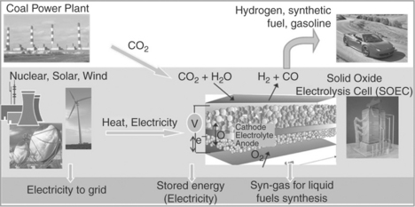
6.1 The envisioned coupling of energy sources and CO2 sources to the high-temperature co-electrolytic devices.
The development and successful demonstration of solid oxide cells for electrolytic hydrogen production started more than two decades ago.10,11 Dönitz presented results from the HOTELLY project for a single cell and stack including durability tests.10 The project was stopped around 1990, although extensive research and development in the field of SOFCs has taken place internationally since then. The efforts have resulted in optimized materials for high-performing, long-term stable cells.12 Those recent developments in the SOFC field now allow the opportunity to transfer them, in part and where technically suitable, to SOECs. In the past few years, the SOEC field, too, has attracted many research groups and the results suggest that this technology is much more efficient than low-temperature alkaline electrolyzers. Several efforts have also been made to improve the durability of the cells and to optimize the performance of the electrodes.’13−18 Because the hydrogen or syn-gas production price is proportional to the resistance of the cell, obtaining a low internal resistance of the cell is important, not only initially but also during the thousands of hours of electrolysis operation, for the development of commercially interesting reversible SOECs. To date, only limited results on the durability of high-performance SOECs have been reported in the literature. Even though solid oxide cells are reversible in theory, and can have comparable initial performance in electrolysis and fuel cell mode, the degree of degradation of the cells during long-term testing in fuel cell and electrolysis operation modes can be dramatically different,19 disfavoring the latter. Therefore, it is necessary not only to produce highly efficient SOECs but also long-term durable cells and systems. This chapter summarizes the current state-of-the art materials used in solid oxide electrolysis tests, discusses the main degradation modes and mechanisms identified to date, and presents several recent developments in designing active and durable materials for electrolysis and the reversible operation of such systems.
6.1.1 Expected scale of impact
On the basis of the 2010 annual report of US-DOE Idaho National Laboratory,20 the co-electrolysis process, when coupled with nuclear energy systems, can save up to 50% of the carbon from the direct use of liquid fuels, and entail 99% less CO2 emissions than the ‘standard’ coal-to-liquid fuel conversion. To illustrate the issues and potential pathway for the integration of renewable energy sources to the electric grid, consider the case of wind energy. While today wind electricity with very few exceptions is uneconomic without subsidies, wind resources are large and the production economics are improving. This leads to the question, if the production cost of wind electricity continues to decrease, is it possible for wind to become an economic large-scale source of energy? Low wind electricity production costs do not imply low-cost electricity to the customer unless that electricity is generated when the customer needs electricity. Unfortunately, wind energy production does not match customer demand either during the day or seasonally. In parts of the United States with deregulated grids, power producers pay the grid to take electricity at times of very low electricity demand. The economic viability of wind depends upon integrating wind into a larger utility system and addressing the time mismatch between production and consumption. A recent example that demonstrates the potential impact from reversible SOFCs/SOECs is reported by Forsberg et al., who examined alternative system designs to enable the large-scale economic use of wind energy.21,22 To minimize costs, these systems produce electricity from wind, natural gas and nuclear power, to supply the total electricity demands for the Midwest electricity grid and hydrogen to Chicago or Alberta refinery markets. The Midwest electricity grid includes the central United States and parts of Canada and has the best wind resources in the United States. Real electricity demand and wind data were used. The economics were found to be favorable assuming (1) significant reductions in wind turbine costs, (2) successful commercialization of high-temperature electrolyzers that can also operate in reverse as fuel cells and (3) higher priced natural gas. These were considered reasonable assumptions looking a few decades into the future. To realize such large-scale impact, it is important to advance our knowledge and discover materials that can enable highly efficient and durable high-temperature electrolyzers that also operate in reverse as fuel cells, and can couple to various energy sources such as wind, solar and nuclear, to produce a mix of electricity and fuels. This strategy makes it possible to integrate a larger range of clean energy sources than we currently have in the electric grid.
6.2 Operating principles and functional materials
6.2.1 Operating principles
Solid oxide electrolysis cells can be seen in simple terms as the reverse operation of SOFCs.1,23 Therefore, reversible cells operate through a solid oxide electrocatalytic system, which functions reversibly in both the electrolytic and the fuel cell modes. An SOEC consists of three functional solid-state layers, composed of a porous high-surface-area cathode, a dense electrolyte and a porous high-surface-area anode. The basic reactions taking place in the SOEC and SOFC mode are illustrated in Fig. 6.2. In SOEC mode, steam is introduced at the cathode side (hydrogen electrode), where it is reduced to release hydrogen gas and oxide ions in the process. Oxide ions migrate through the cathode and the electrolyte into the anode (oxygen electrode), and get oxidized at the anode. This is accompanied by the release of electrons and combination of oxygen atoms to form oxygen molecules that are carried away from the cell. In a co-electrolytic mode, the electrochemical reduction of steam and carbon dioxide takes place together on the cathode, both processes releasing oxide ions, and forming a mixture of hydrogen and carbon monoxide gases. While in SOFC, hydrogen and carbon monoxide can serve as the fuel that is oxidized, in SOEC the steam and carbon dioxide are reduced electrochemically. The anode and cathode must possess high ionic and electronic conductivity and high activity for surface reactions. The electrolyte must have high ionic conductivity and electronic insulation.
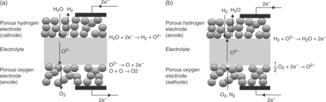
6.2 Basic reactions in solid oxide cells (a) in electrolysis mode as an SOEC and (b) in fuel cell mode as an SOFC.24
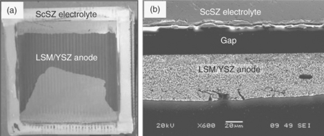
Initially, SOECs were developed as tubular cell structures to avoid sealing problems, which is a major issue in segregating the produced H2 and O2 gases in planar cells, particularly over multiple thermal cycles.25 Today, with advances in sealing technologies, the trend in cell design is to employ planar structures. A tubular and a planar solid oxide cell and its microstructure are shown in Fig. 6.3. The conventional electrode microstructure comprises of nano-to-micro-scale percolated particles, with high surface area and with ionic and electronic connectivity. A high packing density and significantly smaller hot volume in the planar cells than that attainable by a tubular design renders the planar configuration more attractive.13 Additional advantages to the planar design include lower manufacturing costs and shorter current paths that reduce the ohmic cell resistance.26 Planar SOECs, similar to planar SOFCs, are designed as either electrolyte-supported or electrode-supported. The former employs the electrolyte as the thick support structure for the cell and is more suitable for operation at high temperatures which reduces the often large ohmic resistance associated with a thick electrolyte. In an electrode-supported cell one of the electrodes is the thickest part of the cell, supporting a film electrolyte of about 10 μm or less in thickness. Such a design has been developed in order to minimize ohmic resistances in SOFCs operating at intermediate temperatures, and may also be applied to intermediate-temperature SOECs. During the operation of an SOEC system, heat is generated in the stack as the result of irreversible losses due to ohmic resistance and electrode overpotentials. The magnitude of these energy losses depend on operating conditions such as the stack temperature and average current density, as well as materials selection and cell and stack geometry. Finally, it is important also to note that the SOECs are fully scalable because the main functionality of the system depends on each individual cell. To attain the desired rate of hydrogen production rate, the cells are stacked together to form ‘stack modules’ and stack modules are integrated together to form a plant on the basis of cell and system functionality. Therefore, decreasing the cost of each ‘cell’ through higher activity and increased durability of materials has direct impact on the overall viability of these systems.
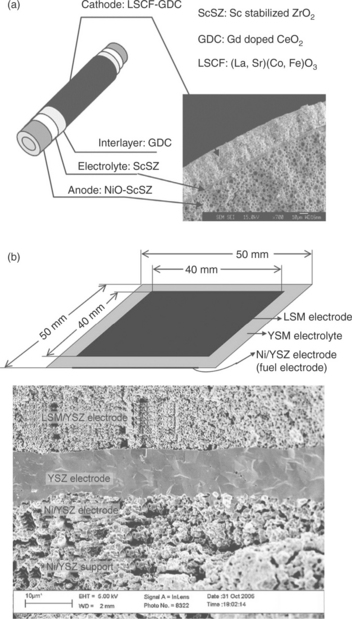
6.3 (a) A tubular (from Reference 23), and (b) a planar solid oxide cell design (from Reference 27), and the representative microstructures shown by cross-sectional electron micrographs.
6.2.2 Functional materials
The efficiency of solid oxide cells depends on the reaction kinetics on both the anode and the cathode, and the oxygen transport kinetics through the electrolyte. The chosen materials and structures for reversible solid oxide cells must enable fast kinetics for the electrode reactions and for transport of oxygen ions through the electrolyte. The high efficiency of the present SOFCs and SOECs is, in part, enabled by their high operating temperatures, typically 800–1000°C. They do not require expensive platinum catalyst materials, as is currently necessary for low-temperature (polymer electrolyte membrane) fuel cells. However, the use of oxide materials for electrolyte and electrode functionality renders the conductivity and activity acceptably high thus far only at elevated temperatures. In advancing the SOFC technologies, there is increased interest in intermediate-temperature operation in the 823–1073 K range to allow for a wider range of materials, more cost-effective fabrication methods and increased durability. The reduction in operating temperature has also been observed for the SOEC field in the limited number of experimental projects reported over recent decades,28,29 where the temperature at which the cells are tested has decreased from 1273 to 1073 K.
Here the most commonly used electrolyte and electrode materials in SOEC tests are summarized, and the challenges associated with them and new opportunities in functional SOEC materials design are discussed in the following sections. The state-of-the-art SOFC materials have formed a starting point for the SOEC development. Typical electrolytes used are made of doped zirconia, for example, yttria-stabilized zirconia (YSZ) or scandia-stabilized zirconia (ScSZ), which is a fluorite-structured oxide. SOEC cathodes are made of composites of zirconia and Ni metal catalyst, Ni/YSZ. Doped perovskites based on LaCoO3 1 for example La1 – xSr x CoyFe1 – y O3 – δ (LSCF), and composite electrodes made of a perovskite and a solid electrolyte such as La1 – x SrxMnO3 – δ (LSM)/YxZr1 – x O2 – δ (YSZ) have been proposed and used as an alternative to the conventional LSM for anodes in SOECs.30 These materials present high electronic conductivity, high oxygen ion conductivity, and reasonably high oxygen surface exchange coefficient for fast reaction kinetics at the gas/electrode interface. Both in the YSZ and in the LSM and LSCF structures, the incorporation and transport of oxygen relies on the availability and mobility of oxygen vacancies,31 as illustrated in Fig. 6.4. However, the reaction mechanisms and the reaction steps that govern the kinetics of oxygen evolution on the anodes has not yet been studied, contrary to the increasing interest and state of knowledge on elucidating the cathodic reactions on the same materials in SOFCs.32
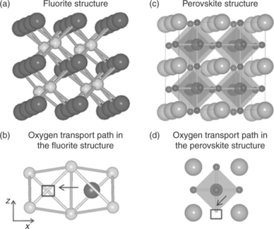
6.4 Crystal structure and oxygen migration path in the fluorite structure (a, b), representative of ZrO2 and CeO2 systems (large and small spheres are oxygen and cation sites, square is vacant oxygen site), and in the perovskite structure (c, d), representing LaGaO3, LaMnO3 and LaCoO3 systems (small, large and medium spheres are oxygen, A-site cation and B-site cation sites, squares are vacant oxygen site). Arrows in (b) and (d) show schematically the path for the oxygen migration towards the vacant site. (Source: From Reference 31.)
An important motivation for use of the traditional SOFC materials in SOECs has been that a positive correlation between the initial performance of air electrodes in both SOFC and SOEC modes was observed.27,33 However, there are contradictions in the literature about the performance, in particular, of LSM/YSZ in SOEC mode. Some authors have reported that LSM/YSZ electrodes show poor performance under electrolysis conditions.34,35 Wang et al.34 concluded that the enhancement associated with cathodic polarization is lost during electrolysis due to anodic polarization. In contrast, the best results in SOEC cells to date were reported by Jensen et al.4 using LSM/YSZ composite oxygen electrodes. Laguna-Bercero et al.36 recently addressed some of these contradictions by consistently testing the reversible anodic cathodic performance of LSCF and LSM/YSZ composite electrodes. It was found that both types of compositions show a good initial performance with low area-specific resistances, ASRs (shown in Fig. 6.5), in good agreement with Jensen et al.’s results, and with the performance of LSCF better than that of LSM/YSZ. SOFC–SOEC galvanostatic experiments were also performed for both samples and the ASR values of 0.93 and 0.79 Ω.cm2 were obtained for the LSM and the LSCF samples, respectively, showing a non-linearity of the cell response under anodic and cathodic polarization at temperatures up to 800°C. This non-linearity is important to note because it indicates different governing mechanisms on the same material when polarized cathodically versus anodically. Microstructurally, no evident differences between these electrodes were found after the combined SOFC–SOEC experiments; however, the LSM/YSZ was associated with an evident degradation rate.
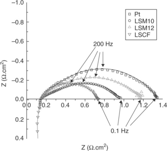
6.5 Electrochemical impedance measurements recorded at OCV and 800°C for single solid oxide cells with Pt, LSM/YSZ and LSCF anodes, and with the Ni/YSZ cathode for electrolysis under 70% H2O/24% N2/6%H2. (Source: Reference 36.)
6.3 Degradation mechanisms in solid oxide electrolysis cells
While technically promising and carrying the advantages mentioned earlier, the operation of solid oxide cells in electrolytic mode, especially when cycled between fuel cell and electrolytic modes, has thus far been challenged by the degradation of the materials.27 The research needs for enhancing our understanding of materials behavior in these systems and for their further development to enable durable and economic operation are broad. First, the polarization resistance of the cells was found to be typically higher (by 2–3 times) and the degradation rate was found to be faster when operating in electrolytic mode compared to fuel cell mode.28 The oxygen electrode is primarily responsible for this loss in efficiency and durability.28,37,38 Figure 6.6 shows the degradation rate, corresponding to an 18% loss in H2 production rate over 1000 h of operation of SOECs, observed in the electrolysis tests performed at Idaho National Laboratory in a 25-cell SOEC stack.39 The governing reasons for such fast degradation in SOECs have been investigated, and although not complete, are presented in the following. Second, there are further uncertainties about the stability of cell materials in the presence of CO2 when considering co-electrolytic operation.6 A third challenge is related to the operating temperatures. Reduced temperatures help minimize material degradation. However, they also lead to increased electrolyte ohmic resistance and electrode polarization losses given the thermally activated behavior of both the ionic transport and the charge transfer processes. For distributed production of hydrogen or syn-gas, it is desirable to develop electrolysis cells which can operate at moderate temperatures, perhaps even as low as the 300–400°C range. This way, small, local co-electrolysis plants might be established, connected directly to a local power station (e.g., local wind turbine, or existing nuclear plant) and producing synthetic fuel for the local area. For this to succeed, it is necessary to develop completely new materials and structures. At reduced temperatures (< 700°C), while ohmic resistance can be compensated, in part, by decreasing electrolyte thickness, the polarization loss on the oxygen electrode surfaces often becomes the greatest obstacle towards achieving adequate electrochemical performance. The situation is similar to the challenges with the slow oxygen reduction kinetics on the cathodes of SOFCs at reduced temperatures.
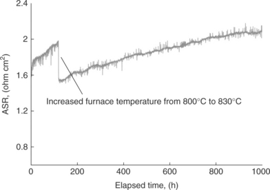
6.6 Area-specific resistance (ASR) of a 25-cell SOEC stack as a function of time for a 1000-h electrolysis test. (Source: Reference 39.)
A key reason for the faster degradation of materials in electrolytic mode is the use of materials that were originally optimized for fuel cell mode,27,28,34,36,40 despite the fact that principally different thermodynamic environments surround the materials in the fuel cell versus the electrolytic mode of operation. The use of SOFC materials has been a reasonable starting point for reversible SOECs. However, further realization of these devices requires new materials and structures that are stable under both the fuel cell and electrolytic conditions. The leading causes of degradation associated with the functional cell components in SOECs are reviewed later on the basis of the research reported to date. This is not a comprehensive list, and only highlights the perceived major degradation modes in SOECs. Unfortunately, the published literature that addresses degradation and related issues in SOECs is limited. Cr poisoning of the oxygen electrode,41−44 segregation of cations to the surface of the catalyst,45−49 interdiffusion of cations between the electrolyte and oxygen electrode grains,50 and the red-ox stability of the hydrogen electrode51 were identified to be crucial processes leading to the degradation of SOFCs. At a high level, SOECs are expected to be subject to similar causes of degradation, which are of interest here. The knowledge of degradation mechanisms in SOFCs can be a starting point for the SOECs and can offer some guidance in identifying the research areas. Because of this reason, some known degradation mechanisms in SOFCs are also included here. However, the exact mechanisms and the consequences could be distinct from those in an SOFC operation because of the different thermodynamic and electrochemical conditions and the reverse path of ionic and electronic transport in SOECs compared to SOFCs.
6.3.1 Delamination of the oxygen electrode
The delamination of the anode (oxygen electrode) from the electrolyte has been observed as a major problem leading to SOEC performance degradation (Fig. 6.7).52 The build-up of a high oxygen partial pressure at the electrode/electrolyte interface while pumping the oxygen flux into the anode from the electrolyte is thought to be one main reason for the detachment of the electrode layer from the electrolyte. According to Virkar’s model,54 one of the principal modes of failure of solid-state anode/electrolyte interface is related to the generation of high chemical potentials and corresponding ultrahigh pressure of neutral species within the electrolyte in the vicinity of the interface. For example, in an oxygen-ion-conducting solid electrolyte such as YSZ, under suitable thermodynamic conditions, the oxygen chemical potential within the solid electrolyte, ![]() , may exceed the chemical potential of gaseous oxygen. That is, it is thermodynamically possible to achieve
, may exceed the chemical potential of gaseous oxygen. That is, it is thermodynamically possible to achieve ![]() >
> ![]() in SOEC operating conditions. Because the chemical potential of gaseous reactants is a function of the partial pressure, a higher
in SOEC operating conditions. Because the chemical potential of gaseous reactants is a function of the partial pressure, a higher ![]() in YSZ may be achieved compared to that the anode can accommodate and result in electrode delamination. An interpretation of this problem solely based on ex situ visual observations, without a theoretical basis, may be misleading especially because these observations are gathered as aftermath results of some critical damage to the cell materials. While an in situ observation and proof of this mechanism is not yet available, it is consistent with the hillock-like delamination of dense thin-film LSM micro-electrodes from YSZ electrolyte upon anodic polarization reported by Brichzin et al.55,56 It is important to recall that the typical electrode materials tested in SOECs thus far are made of the perovskite oxides such as LSM and LSCF, which accommodate oxygen vacancies and rely on them for oxygen transport and oxygen exchange. However, they do not accommodate oxygen excess in a stable manner in the crystal structure. Therefore, the mitigation of this problem may consider anode or interface materials which can also accommodate oxygen excess, as will be discussed in Section 6.6.
in YSZ may be achieved compared to that the anode can accommodate and result in electrode delamination. An interpretation of this problem solely based on ex situ visual observations, without a theoretical basis, may be misleading especially because these observations are gathered as aftermath results of some critical damage to the cell materials. While an in situ observation and proof of this mechanism is not yet available, it is consistent with the hillock-like delamination of dense thin-film LSM micro-electrodes from YSZ electrolyte upon anodic polarization reported by Brichzin et al.55,56 It is important to recall that the typical electrode materials tested in SOECs thus far are made of the perovskite oxides such as LSM and LSCF, which accommodate oxygen vacancies and rely on them for oxygen transport and oxygen exchange. However, they do not accommodate oxygen excess in a stable manner in the crystal structure. Therefore, the mitigation of this problem may consider anode or interface materials which can also accommodate oxygen excess, as will be discussed in Section 6.6.
6.7 (a) A 10 cm × 10 cm SOEC surface shown from the anode side after operation. The black parts are the remnants of the anode after severe delamination of the electrode from the electrolyte. (b) A cross-section scanning electron microscopy image showing the detachment of the oxygen electrode from the electrolyte interface after electrolysis tests. (Source: Reference 53.)
6.3.2 Poisoning of the hydrogen and oxygen electrodes by contaminants
The transport of contaminants, such as Cr, Ni and Si, from interconnects and seals followed by their deposition on the electrode materials either blocks the active electrocatalytic sites or results in the formation of secondary phases that are inactive and insulating local phases.1 Research to date has enabled a better understanding of the effect of these poisoning species in SOFC degradation kinetics and has helped control the degradation rate in SOFC stacks down to lower than 2%/1000 h.57 On the other hand, investigation of these species in the context of degradation mechanisms in SOECs is still in its early phases.38,58,59 The source of contaminants and their transport mechanism, poisoning and deactivation of reaction sites and their relative impact on degradation is important to understand and control for the viability of reversible solid oxide electrolytic and fuel cells.
SiO2 poisoning of the hydrogen electrode (cathode)
The SOEC tests at Risø National Laboratory has uncovered a silica-related poisoning of the hydrogen/steam electrodes in SOEC, completely unlike that expected in SOFC conditions.58 The cells produced were shown to operate well both as fuel cells and electrolysis cells initially. The ASR obtained from the I–V curves run in electrolysis mode was higher than for fuel cell I–V curves for the same cells. At constant galvanostatic electrolysis conditions, the internal resistance of the cells was found to increase significantly during the first 100 h, after which the cell voltage stabilized. A cell that has been passivated during electrolysis could at least be partly activated by operating the cell at constant fuel cell conditions. The initial passivation of the SOECs was found to originate from Si species volatilized from the applied glass sealing and deposited as SiO2 on the active sites (triple phase boundaries) of the Ni/YSZ cathode near the electrode/electrolyte interface. The elemental analysis showing the distribution of Si in the Ni/YSZ cathode is shown in Plate IV (see color section between pages 238 and 239).40 The mechanism for the SiO2 deposition was found to be driven by the high steam partial pressures specific to the SOEC conditions, and not expected to take place in SOFC (cathodic) conditions of the same electrode. In the electrolytic conditions, the vapor pressure of Si(OH)4 over the glass sealing was found as the source for the detected Si-containing impurities in the tested cells. Since the origin of the main silicon source is Si(OH)4(g) from the sealing, then the equilibrium of the reaction
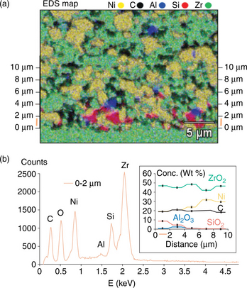
Plate IV (a) Energy dispersive spectroscopy (EDS) mapping of Si (red), Al (blue), Zr (green), Ni (yellow) and C (black). The carbon comes from holes in the porous electrode filled with epoxy. (b) Additive EDS spectra of all point analyses lying within a specified distance from the electrode/electrolyte interface. Concentrations of compounds are calculated based on the additive EDS. The concentration for each compound is given as a function of interval distance from the electrolyte in the inset. (Source: From reference 40.)
is forced toward the formation of a glassy SiO2(s) silica phase in the regions of the cell where the most steam is reduced to hydrogen. This takes place in the few micrometers of the hydrogen electrode closest to the electrolyte, and thus leads to the highest silica content being closest to the electrode/electrolyte interface. This is in agreement with the gradient for silica content found for the tested SOEC cathodes by Hauch et al.40 This degradation mode can be avoided by replacing the albite glass sealing on the cathode side of the cell test setup, and the replacement strategy has been shown to avoid Si species from being deposited in the Ni/YSZ electrode.40
Cr poisoning of the oxygen electrode (anode)
Cr poisoning of the SOFC cathodes has been extensively documented in the literature.41−44 Three main hypotheses prevail to explain the progression of the degradation mechanism. The first hypothesis suggests that this process is initiated through the formation of Cr6 +- containing gaseous species, such as CrO3 or CrO2(OH)2, from the oxidation of chromium oxide on the interconnect.60 The volatile Cr species are then reduced at the triple phase boundaries of electrode, electrolyte and air and form solid Cr2O3 and other Cr-rich phases, thereby inhibiting the electrochemistry of the electrode and leading to polarization losses.61,62 For example, the solid Cr2O3 species could react with the perovskite cathode LSM to form La1 – xSrxMn1–yCryO3 and (Cr1 – yMny)O 1.5-δ, with the formation of (Cr1 – yMny)O1.5–δ spinel being the driving force for the reaction.62 Furthermore, Matsuzaki and Yasuda found that not only the SOFC cathode but also the electrolyte material could influence the reduction of the volatile Cr-containing species due to the electrochemical state at the cathode/electrolyte interface.41 The second hypothesis suggests that, along with the vapor phase reduction, solid-state diffusion of the Cr-containing species into the oxygen electrode and chemical dissociation of the electrode material are underlining mechanisms in the deposition of Cr.63 Finally, the third and a more recent hypothesis by Zhen et al.64 and Chen et al.43 suggests that the Cr deposition process at the oxygen electrode is thermodynamically driven and kinetically limited by a nucleation reaction between the Cr species that is being transported and a ‘nucleation agent’ on the electrode. In the LSM electrode, the nucleation agent was identified to be the manganese species (Mn2+), and for LSCF electrode, it was suggested to be the SrO species segregated at the electrode surface.64 These references also assert that the driving force for the deposition of Cr species at the LSM cathode is the generation of Mn2 + species, which then react with gaseous Cr species, forming Cr–Mn–O nuclei and, subsequently, the (Cr,Mn)3O4 spinel. In addition to the electrode, the effects of Cr-related degradation have also been reported for the contact layer of SOFC cathodes. In that case, the formation of a less conducting oxide layer forming between the contact layer and the interconnect was suggested to be responsible for the degradation of the cells due to loss in the electronic path from the interconnect to the cathode.44 Clearly, there is still no consensus about the exact and global mechanism of how Cr poisons the electrochemical performance of the electrodes due to the complicated dependencies on structure, operating temperature, atmosphere, and ionic and electronic conductivities. Furthermore, the stability of the possible reaction products between Cr and a given oxygen electrode material can differ between the SOFC and SOEC due to the different thermodynamic conditions at the corresponding electrodes.
Severe chemical and structural degradation of La0.8Sr0.2CoO3 (LSC) on the anode side of SOECs was recently reported by Sharma and Yildiz when the cells were operated in the presence of Cr-containing interconnects.38 The formation of poorly conducting secondary phases due to the dissociation of the LSC contact layer was found to be an outcome of Cr poisoning. This leads to the deterioration of the electronic activation and electrocatalytic activity of the anode. Characterization of the degraded cells by Auger electron spectroscopy and analytical transmission electron microscopy indicated that the dominant cause for the LSC dissociation is the extensive inward transport of the Cr-containing phases from the stainless steel interconnects into the LSC microstructure. This process was driven by the thermodynamics governing the La–, Sr– and Cr–O phases specifically under electrolytic polarization and oxygen partial pressure conditions. The results suggest a mechanism for Cr deposition, which can nucleate between the volatile Cr-containing species, CrO3 or CrO2(OH), and the La–O and Sr–O segregates on the initial LSC surface and form secondary phases. The illustration for this governing process is shown in Fig. 6.8, accompanied by the elemental distribution in the deteriorated microstructure of LSC. The importance of surface cation segregation in a broader context is discussed in the next section, and it seems to play an important role in aggregating the Cr poisoning of LSC in SOEC anode. The exact mechanism by which Cr causes such long-range transport of Sr and Co cations, the consequent La–Cr–O phase formations, and the relation of this process to the electrochemical potential and gas pressure conditions in SOEC anode should be further quantified based on the thermodynamics involved in these reactions.
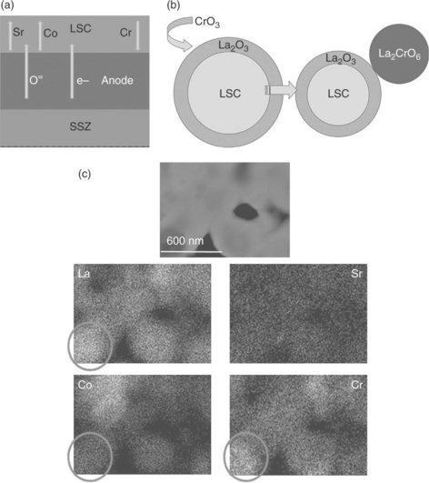
6.8 (a) Illustration of the transport of cations and charge carriers across the degraded SOEC anode/bond layer. (b) Illustration of the suggested reaction mechanism between the Cr species and the LSC surface phases. The surface of the LSC grains is A-site segregated in the as- prepared condition. These A-site-enriched phases on the surface react with the Cr-containing species and form La2CrO6. (c) Dark-field transmission electron microscopy image of a cross-sectional region in the LSC layer, with the elemental maps for La, Sr, Co and Cr at an analysis area of 1.3 × 0.9 μm. No discernable amount of Sr is left in the bulk of the LSC because of a near-complete segregation of SrO onto the top of the deteriorated LSC layer, and the high-Cr content regions are associated with high La-content in the bulk of the microstructure. (Source: Reference 38.)
6.3.3 Cation segregation and phase separation
Cation interdiffusion and segregation can adversely affect the performance of the cells through local changes in the composition and structure. Interdiffusion of cations between the oxygen electrode and the electrolyte was shown to lead to the formation of an electrochemically insulating layer or microstructure in SOFCs and has been the subject of detailed studies.50 Similar to interdiffusion, but different in location, the segregation of cations on especially the cathode surfaces in SOFCs is widely documented and has immense importance for determining the oxygen exchange activity on SOFC cathodes and SOEC anodes. If the extent of such cation interdiffusion and segregation were only small, it would not result in drastic changes in the bulk microstructure, and the original bulk phases could be retained, while the adverse effects would be confined to ‘critical’ interfaces where the segregation accumulates. However, if the movement and flux of cations is significant over the microstructure, these processes can compromise the phase stability and the global electrochemical properties of the cell materials (like the LSC microstructure tested in SOEC anode/contact layer discussed in Section 6.2).
For complex oxides, such as the perovskite family of relevance to solid oxide cells, the surface structure and chemistry (i.e., cation concentration and oxygen non-stoichiometry) are driven dynamically by the surrounding harsh environment at high temperature, in oxygen partial pressure and under electrochemical potentials.45−47,49,65−67 Under these conditions, electrode surface chemistries may vary very richly, and the atomic structure of the surface segregation, not only its composition, is important in determining the oxygen reduction and evolution activity. As a result of cation segregation, the surface could become a ‘different material’ than the bulk phase. Cation segregation is now a commonly observed and acknowledged phenomenon on the surface of the SOFC cathode materials, such as on SrTiO3 (STO),45 (La,Sr)MnO3 (LSM),46−48 (La,Sr)CoO3 (LSC)68 and SrTi1 – xFexO3 (STF).49,69 Such deviations from the bulk nominal composition and phase can directly alter the surface electronic structure and the electrocatalytic activity of the surface. A clear example to this is presented by Liang and Bonnell.70 Their work showed that the segregated Sr-rich islands that form on the annealed SrTiO3 single-crystal surface differ from the unsegregated surface both in atomic and in electronic structure. A much wider band gap (6 eV) was found on the Sr-rich segregated islands compared to that on the unsegregated pristine surface (3.2 eV). Direct evidence to the modified valance and conduction band electronic structure of segregated surfaces under various conditions was also reported on for SrFeO3,71 LSM,72 STO73,74 and (La,A)MnO3 (A = Ca, Sr, Ba).75
Despite the wide-ranging observations on cation segregation on perovskite-type oxides, the answer to how such surface segregation layers influence the oxygen reduction and evolution kinetics remains controversial. Taking Sr segregation as an example, it has been reported that Sr segregation on the surface leads to degradation of oxygen reduction activities on (LSC)68 LSM76 and STF.49 In contrast to these results, other groups have observed the enhancement of oxygen exchange kinetics by purposefully decorating (via deposition) SrO onto the surface of LSC77 and Fe-doped STO.78 However, the physical origin behind these empirical observations is not understood. An important motivating point is the lack of understanding of how the surface structure in the presence of cation segregation affects the oxygen reduction and evolution activity in SOFCs and SOECs. The specific open questions of importance for further research are: (1) What are the non-bulk-like structures that form on these segregated surfaces of perovskite oxides at elevated temperatures (e.g., the La- and Sr-rich surface of LSC shown in Fig. 6.8b)? (2) How is the electronic structure affected by the formation of a new surface composition and structure? (3) How does the segregated surface electronic structure affect the oxygen reduction and evolution activity of the electrode?
6.3.4 Red–ox stability of the hydrogen electrode
Reduction and oxidation (red-ox) cycling in SOFC anodes has been identified as an issue that leads to the instability of the Ni/YSZ electrode. Volume changes in Ni–YSZ electrodes due to reduction and oxidation of Ni catalyst particles result in mechanical stresses and consequently to microstructural changes in the electrode, which degrades its activity. NiO formation is another factor that deteriorates the surface activity of the catalyst. SOEC tests at Ris0 National Laboratory have also found significant microstructural degradation in the Ni–YSZ cathode at the high steam partial pressure conditions typical of electrolysis, especially when the cells were run at high current densities. The loss in performance for the high current density, hightemperature SOEC tests at − 2 A/cm2, 950°C and ρH2o = 0.9 was dominated by a 200% increase in the polarization resistance of the cathode over only 68 h (∆Rp = 21%/68 h).58 Postmortem microchemical analysis of these cells showed significant structural changes at the hydrogen electrode/electrolyte interface due to the relocation of Ni (mechanism illustrated in Fig. 6.9). A 2–4 μm thick dense layer of Ni on YSZ formed at the interface, caused by the relocation of Ni particles. Such a layer completely blocks the oxygen transfer from the cathode into the electrolyte. For SOECs aimed at these conditions, different hydrogen electrode materials, potentially all-ceramic-based ones, need to be considered.
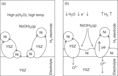
6.9 Illustration of the possible mechanism for the changes in the microstructure at the YSZ–Ni/YSZ interface observed for a high current density SOEC test. (a) The YSZ–Ni/YSZ interface at OCV prior to degradation at high current density electrolysis testing. Triple phase boundaries (3PB) are marked by dark gray squares. The high ρH2O and high temperature lead to a considerable activity of Ni(OH)2. (b) The YSZ–Ni/YSZ interface upon degradation at high current density electrolysis testing. In this microstructure, YSZ particles have electrical resistance and the electrical potential gradient in the YSZ particles is illustrated by ∆Φ. The 3PB marked by light gray squares are more reducing points than those 3PB marked by dark gray squares and the reduction of nickel hydroxide takes place at the light gray marked 3PB leading to the deposition of a dense Ni–YSZ layer. (Source: Reference 58.)
6.4 Research needs and opportunities
To date the research on materials development and fundamental studies of materials behavior in SOFC functionality has been significantly ahead of those for SOEC. Given the significant impact that can be imparted on the large-scale energy storage capabilities in a sustainable energy systems network, more extensive research on the electrolytic and reversible electrolytic fuel cell functionality of these systems is desirable and necessary. As was the focus of Section 6.5, degradation of the currently used SOFC materials in electrolytic or reversible mode is an outstanding challenge. Addressing this challenge via the development of more active and more durable materials requires first a much improved fundamental understanding of all the thermodynamic and kinetic conditions that drive the electrochemical processes in SOECs. Rational design of novel materials and structures to improve the activity and durability of solid oxide cell materials also requires the advancement of our knowledge on the electrochemical reaction and degradation mechanisms at the molecular level. This can be enabled by a systematic integration of bulk- and interface-sensitive experiments and computational theory from the electronic and atomic level. Especially the latter, unfortunately, is currently lacking in specifically the SOEC materials studies. The design and synthesis of surfaces, for example on the basis of a favorable strain state or engineered hetero-nano-structures, also provide the potential for a high density of fast reaction sites for O2 evolution on the anode and for CO2 and H2O(g) reduction on the cathode of the SOECs, as recent research from the SOFC field implies.79−81
While all these necessitate a large-scale, long-term and coordinated network of research and development activities, there already are early indications of successful results with respect to durability when the materials design considers fundamentally the electrolytic conditions. Two examples for such novel materials, one for the oxygen electrode and one for the hydrogen electrode, are highlighted in the following. In both, the targets are single-phase mixed ionic electronic conducting materials that are superior especially in terms of stability and durability for reversible electrolytic and fuel cell functionality of solid oxide cells.
6.4.1 Advanced oxygen electrode materials
The majority of the tested oxygen electrode materials in the electrolytic or reversible solid oxide cells have been based on the experience gained from the SOFC-related research, most commonly using the perovskite structured La1 – xSrxMnO3 and La1 – xSrxCo1 – yFeyO3.82 As discussed in Section 6.5, while these materials are acceptably stable under relatively reducing conditions of SOFCs, they exhibit severe delamination of the oxygen electrode from the electrolyte in SOEC mode.38 This is because these perovskites are not very flexible in maintaining phase integrity in oxygen poor as well as in oxygen-rich conditions.83 In SOECs, oxygen flux accumulates at the electrode-electrolyte interface, builds up an internal oxygen pressure, and the typically oxygen-deficient perovskites cannot inherently accommodate oxygen excess, for example in the form of interstitials. Due to this inherent structural limitation, the critical interface between the SOEC anode and electrolyte eventually ruptures.38,39,53 Therefore, a key requirement for the oxygen electrode in reversible solid oxide cells is a flexible structure that accommodates oxygen excess in SOEC mode and is also stable when oxygen poor conditions prevail in SOFC mode.
A report by Laguna-Bercero et al presents La2 – xSrxCo0 5Ni0.5O4 ± s (LSCN) as a novel electrode for reversible solid oxide cells.83 From electrochemical tests, LSCN was found to perform well and stable in both the electrolytic and fuel cell operation. ASR values obtained from the slope of the I-V curves (Fig. 6.10a) showed that at higher temperatures (800–850°C) the cell is performing equally in both operation modes. ASR values at 850°C were 1.92 and 2.05 Ωcm2 for SOFC and SOEC, respectively. At lower temperatures, 700°C, on the other hand, lower ASR values were obtained under electrolysis mode (2.60 Ωcm2) in comparison with those obtained under SOFC mode (4.13 Ωcm2). It is remarkable that these results for SOEC performance were obtained at a low steam partial pressure (ρH2O = 0.03 atm), and thus, even lower ASR values are expected at the higher steam concentrations and at high current densities. Furthermore, even an activation of the LSCN electrode was observed under anodic polarization lasting up to about 2 h, as seen in the AC impedance data in Fig. 6.10b.
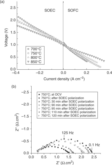
6.10 (a) I-V curves in both SOFC and SOEC mode recorded at different temperatures for the electrolyte-supported Ni–YSZ/10Sc1CeSZ/LSCN single cell. (b) Nyquist plots recorded at 750°C, showing the electrode activation upon SOEC (anodic) polarization. All impedance spectra were recorded at OCV which was constant at 0.994 V. (Source: Reference 83.)
The key to the successful demonstration of this material in reversible electrolytic fuel cell functionality is its structure that can accommodate both oxygen interstitials and vacancies depending on the surrounding thermodynamic conditions. LSCN is a Ruddlesden-Popper phase with the K2NiO4 structure, which is a layered perovskite-related system. The advantage of this material structure for the solid oxide cell oxygen electrode is its stability over a wide range of oxygen pressures. It can adopt a range of possible oxygen non-stoichiometries including both oxygen-rich states (Ln2NiO4 + δ) and oxygen-deficient states (Ln2NiO4-δ), and thus can perform stable in SOEC and in SOFC modes of operation.84 Especially its capability to house oxygen-rich stoichiometry, in the form of oxygen interstitials, renders this structure as a good candidate to avoid the electrode-electrolyte interface delamination problem in electrolytic operation. Furthermore, components of this family of materials were shown to exhibit very fast oxygen diffusion as well as fast oxygen exchange kinetics, due to a layered and flexible structure that permits oxygen interstitials to migrate easily. Recent theoretical and experimental research on one member of this structure family, the (La,Sr)2CoO4 exemplified in Fig. 6.11, explained and demonstrated the favorable oxygen reaction sites and diffusion paths in this material.85−87 In contrast to the vacancy-mediated surface reactions and oxygen transport in LSM and LSCF (as illustrated in Fig. 6.4), LSCN and other K2NiO4-structured materials incorporate and transport interstitials by an interstitialcy mechanism in oxygen-rich conditions as at the anode-electrolyte interface in electrolytic mode. This structure, with alternative cations at the A- and B-site that can further improve surface oxygen exchange kinetics, presents a promising route for development of stable and highly active oxygen electrodes for reversible solid oxide cells.

6.11 Atomic structure along the interstitialcy migration path in La2CoO4 + δ with the K2NiF4 Ruddlesden-Popper structure, at the initial, intermediate, and saddle points. A: the migrating interstitial oxygen atom and B: the oxygen atom on the LaO plane. The CoO6 octahe- dra (shaded box) cooperatively and flexibly move from a tilted to an untilted configuration to accommodate the interstitialcy migration. The solid lines connect the top and bottom oxygen atoms in the CoO6 octahedra, indicating the extent of tilt with respect to the reference dashed lines along the z-axis. (Source: From Reference 85.)
6.4.2 Advanced hydrogen electrode materials
Conventionally tested hydrogen electrodes in electrolytic and reversible modes are also based on the most widely studied and used anodes of SOFCs, in particular the composite Ni/YSZ. Instability of the Ni/YSZ against red-oxcycling58 and in high steam partial pressures is discussed in Section 6.5. This problem in practice necessitates the feeding of a small quantity of hydrogen at the inlet of the cathode of the SüEC and complicates the cell design and decreases the cell efficiency.
In contrast to the metal/oxide composite Ni/YSZ, single-phase oxide ceramics are generally stable to red-ox cycling and could therefore be operated without the complication of hydrogen feed in the electrode inlet. Tsekouras and Irvine showed that the oxygen-excess La0.3Sr0.7TiO3 + δ, A-site-deficient La0.2Sr0.7TiO3 and undoped SrTiO3 perovskite oxides can serve as very active and stable hydrogen electrodes (cathodes) in SüEC, with favorable chemical, mechanical, thermal and red-ox stability.88 Oxygen-excess compound is characterized by local oxygen-rich defects randomly distributed within the perovskite framework that induce fast conduction.89 The A-site deficient compound, as part of the LaxSr1 – 3x/2TiO3 series (x = 0.2), has been shown to be also a promising SOFC anode material.51 Steam electrolysis performance of these materials was largely independent of the presence or absence of hydrogen in the cathode inlet (as seen in Fig. 6.12), reflecting the red-ox stability of these perovskites and representing a possible advantage over the state-of-the-art Ni/YSZ composite cathode. Such favorable performance was realized particularly because this family of materials has good electronic conductivity by forming Ti3 +/Ti+ 4 couples in the reducing conditions of an SüEC cathode, in addition to surface area effects and good ionic mobility. Doping of the B-site in this material with Fe would be a good strategy to enable good conductivity also in the oxidizing conditions the SOFC operation, as would be required in a reversible cells.
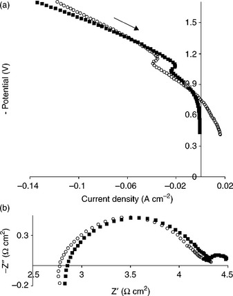
6.12 The effect of the presence or absence of hydrogen in the cathode inlet of an electrolysis cell based on a La0.3Sr0.7TiO3+↓ cathode. (a) Current–voltage (I-V) curves and (b) electrochemical impedance spectroscopy under − 1.5 V bias. All measurements were carried out at 900°C. Empty circles: 47%H2O/3%H2/50%N2. Filled squares: 47%H2O/53%N2. (Source: Reference 88.)
6.5 Summary and conclusions
Solid oxide cells that function reversibly in fuel cell and electrolytic modes offer the possibility of conversion and storage of energy through congruent production of electricity, hydrogen and syn-gas. Coupling of this technology to clean energy sources as nuclear, solar and wind also enables large-scale energy storage and load-following capability in electric power, integration of renewables into the electric grid, and decrease CO2 emissions. In order to achieve this potentially high-impact goal, development of durable, highly active and economical materials is necessary. The challenge in the practical implementation of this technology thus far arises mainly from the degradation of materials especially in the electrolytic mode, and this has rendered the reversibility difficult to achieve. The developments in the optimization of material compositions and structures for SOFCs have paved a reasonable starting point for SOECs. However, this has also been the key reason for the faster degradation of performance in electrolytic mode because those materials were originally optimized for fuel cell mode and principally different thermodynamic environments surround the materials in electrolytic mode. The delamination of the oxygen electrode from the electrolyte due to high oxygen partial pressure build-up at the electrolyte-electrode interface is one distinct deterioration mode found in SOECs when the conventional SOFC cathode materials, LSM or LSCF, are used as the anode. On the other hand, when the oxygen electrode was made of a Ruddlesden-Popper structure material which can accommodate both oxygen excess (under anodic conditions) and oxygen deficiency (under cathodic conditions) stably, the reversible electrolytic fuel cell operation was successfully demonstrated. On the hydrogen electrode side, the red-ox instability issue with the Ni–YSZ electrode and the partial re-deposition of Ni that block the electrolyte surface at high steam pressures in SOEC were avoided by using single-phase ceramics which have high electronic and ionic conductivity in the reducing conditions of the SOEC cathode. Therefore, a key need is the design of materials that take into account the specific thermodynamic conditions and drivers in SOEC mode of operation in addition to the SOFC functionality. For this, advancement of our knowledge on the electrochemical reaction and degradation mechanisms at the molecular level is also necessary. A systematic integration of bulk- and interface-sensitive experiments and computational theory from the electronic and atomic level, studied on a large scale, would benefit this purpose. Finally, the design and synthesis of surfaces and interfaces with a high density of fast reaction sites for O2 evolution on the anode and for CO2 and H2O(g) reduction on the cathode of the SOECs should be pursued for obtaining high-activity electrodes, in addition to the engineering of bulk material compositions and structure.
6.6 References
1. Singhal S.C., Kendall K., Singhal S.C., Kendall K., eds. High-temperature Solid Oxide Fuel Cells: Fundamentals, Design and Applications. Elsevier Ltd, 2003.
2. Mogensen, M., Jensen, S.H., Hauch, A., Chorkendorff, I., Jacobsen, T. Reversible solid oxide cells. Advances in Solid Oxide Fuel Cells III. 2008; 28(4):91–101.
3. Yildiz, B., Hohnholt, K.J., Kazimi, M.S. Hydrogen production using high-temperature steam electrolysis supported by advanced gas reactors with supercritical CO2 cycles. Nucl Technol. 2006; 155(1):1–21.
4. Jensen, S.H., Larsen, P.H., Mogensen, M. Hydrogen and synthetic fuel production from renewable energy sources. Int J Hydrogen Energ. 2007; 32(15):3253–3257.
5. Jensen, S.H., Sun, X.F., Ebbesen, S.D., Knibbe, R., Mogensen, M. Hydrogen and synthetic fuel production using pressurized solid oxide electrolysis cells. Int J Hydrogen Energ. 2010; 35(18):9544–9549.
6. Zhan, Z., Kobsiriphat, W., Wilson, J.R., Pillai, M., Kim, I., Barnett, S.A. Syngas production by coelectrolysis of CO2-H2O – the basis for a renewable energy cycle. Energy Fuels. 2009; 23:3089–3096.
7. Graves, C., Ebbesen, S.D., Mogensen, M., Lackner, K.S. Sustainable hydrocarbon fuels by recycling CO(2) and H(2)O with renewable or nuclear energy. Renew Sust Energ Rev. 2011; 15(1):1–23.
8. Hartvigsen, S., Elangovan, L., Frost, L., Nickens, A., Stoots, C., O’Brien, J., Herring, J.S. Carbon dioxide recycling by high temperature co-electrolysis and hydrocarbon synthesis. Fuel Cell Seminar 2007. 2008; 12:625–637.
9. Graves, C., Ebbesen, S.D., Mogensen, M. Co-electrolysis of CO(2) and H(2)O in solid oxide cells: Performance and durability. Solid State Ionics. 2011; 192(1):398–403.
10. Donitz, W., Erdle, E. High-temperature electrolysis of water-vapor – status of development and perspectives for application. Int J Hydrogen Energ. 1985; 10(5):291–295.
11. Isenberg, A.O. Energy-conversion via solid oxide electrolyte electrochemical- cells at high-temperatures. Solid State Ionics. 1981; 3–4:431–437. [(Aug)].
12. Larsen, P., Bagger, C., Linderoth, S., Mogensen, M., Primdahl, S., Jorgensen, M., et al, Status of the dansish SOFC programYokokawa, H., Singhal, S.C., eds. 5th. SOFC. The Electrochemical Society Inc, Pennington, 2001:28–37. [VIIPV-2001-16].
13. Herring, J.S., O’Brien, J.E., Stoots, C.M., Hawkes, G.L., Hartvigsen, J.J., Shahnam, M. Progress in high-temperature electrolysis for hydrogen production using planar SOFC technology. Int J Hydrogen Energ. 2007; 32(4):440–450.
14. Hauch, A., Ebbesen, S.D., Jensen, S.H., Mogensen, M. Highly efficient high temperature electrolysis. J Mater Chem. 2008; 18(20):2331–2340.
15. Yang, X., Irvine, J.T.S. (La0.75Sr0.25)(0.95)Mn0.5Cr0.5Ο3 as the cathode of solid oxide electrolysis cells for high temperature hydrogen production from steam. J Mater Chem. 2008; 18(20):2349–2354.
16. Laguna-Bercero, M.A., Skinner, S.J., Kilner, J.A. Performance of solid oxide electrolysis cells based on scandia stabilised zirconia. J Power Sources. 2009; 192(1):126–131.
17. Wang, W.S., Huang, Y.Y., Jung, S.W., Vohs, J.M., Gorte, R.J. A comparison of LSM, LSF, and LSCo for solid oxide electrolyzer anodes. J Electrochem Soc. 2006; 153(11):A2066–A2070.
18. Brisse, A., Schefold, J., Zahid, M. High temperature water electrolysis in solid oxide cells. Int J Hydrogen Energ. 2008; 33(20):5375–5382.
19. Hagen, A.M.M., Ramousse, S., Larsen, P.H., Barfod, R., Hendriksen, P.V., Properties and performance of SOFCs produced on a pre-pilot plant scale. M. Mogensen. 6th European Fuel Cell Forum, 2004:930–939.
20. O’Brien, J., Stoots, C.M., Herring, J.S., High temperature electrolysis for hydrogen production from nuclear energy – technology summary. Idaho National Laboratory Technical Report, 2010. [INL/EXT-09-16140].
21. Haratyk, G., Forsberg, C.F. Incentives for reversible hydrogen electrolyzerfuel cells for peak electricity. Holywood, Florida, USA: Transactions of the American Nuclear Society; 2010. [June 2010].
22. Forsberg, C., Haratyk, G., Nuclear wind hydrogen systems for variable electricity and hydrogen production. International Congress on Energy 2011. American Institute of Chemical Engineers: 2011, Minneapolis, Minnesota, 2011. [234665].
23. Suzuki, T., Hasan, Z., Funahashi, Y., Yamaguchi, T., Fujishiro, Y., Awano, M. Impact of anode microstructure on solid oxide fuel cells. Science. 2009; 325(5942):852–855.
24. Ni, M., Leung, M., Leung, D. Technological development of hydrogen production by solid oxide electrolyzer cell (SOEC). Int J Hydrogen Energ. 2008; 33(9):2337–2354.
25. Udagawa, J., Aguiar, P., Brandon, N.P. Hydrogen production through steam electrolysis: Control strategies for a cathode-supported intermediate temperature solid oxide electrolysis cell. J Power Sources. 2008; 180(1):354–364.
26. Larminie, A.D. Fuel Cell Systems Explained, 2nd ed. Wiley; 2003.
27. Hauch, A., Jensen, S.H., Ramousse, S., Mogensen, M. Performance and durability of solid oxide electrolysis cells. J Electrochem Soc. 2006; 153(9):A1741.
28. Herring, J., Obrien, J., Stoots, C., Hawkes, G., Hartvigsen, J., Shahnam, M. Progress in high-temperature electrolysis for hydrogen production using planar SOFC technology. Int J Hydrogen Energ. 2007; 32(4):440–450.
29. Hino, R., Haga, K., Aita, H., Sekita, K. R & D on hydrogen production by high- temperature electrolysis of steam. Nucl Eng Des. 2004; 233(1–3):363–375.
30. Jiang, S.P. Development of lanthanum strontium manganite perovskite cathode materials of solid oxide fuel cells: A review. J Mater Sci. 2008; 43(21):6799–6833.
31. Chroneos, A., Yildiz, B., Tarancon, A., Parfitt, D., Kilner, J.A. Oxygen diffusion in solid oxide fuel cell cathode and electrolyte materials: Mechanistic insights from atomistic simulations. Energ Environ Sci. 2011; 4(8):2774–2789.
32. Adler, S.B. Factors governing oxygen reduction in solid oxide fuel cell cathodes. Chem Rev. 2004; 104(10):4791–4843.
33. Marina, O.A., Pederson, L.R., Williams, M.C., Coffey, G.W., Meinhardt, K.D., Nguyen, C.D., Thomsen, E.C. Electrode performance in reversible solid oxide fuel cells. J Electrochem Soc. 2007; 154(5):B452–B459.
34. Wang, W., Huang, Y., Jung, S., Vohs, J.M., Gorte, R.J. A comparison of LSM, LSF, and LSCo for solid oxide electrolyzer anodes. J Electrochem Soc. 2006; 153(11):A2066.
35. Chen, X.J., Chan, S.H., Khor, K.A. Defect chemistry of La1 – xSrxMnO3 ± δ under cathodic polarization. Electrochem Solid St. 2004; 7(6):A144–A147.
36. Laguna-Bercero, M.A., Kilner, J.A., Skinner, S.J. Performance and characterization of (La, Sr)MnO3/YSZ and La0.6Sr0.4Co0.2Fe0.8Ο3 electrodes for solid oxide electrolysis cells. Chem Mater. 2010; 22(3):1134–1141.
37. Yu, B., Zhang, W.Q., Xu, J.M., Chen, J. Microstructural characterization and electrochemical properties of Ba(0.5)Sr(0.5)Co(0.8)Fe(0.2)O(3 delta) and its application for anode of SOEC. Int J Hydrogen Energ. 2008; 33(23):6873–6877.
38. Sharma, V.I., Yildiz, B. Degradation mechanism in La(0.8)Sr(0.2)CoO(3) as contact layer on the solid oxide electrolysis cell anode. J Electrochem Soc. 2010; 157(3):B441–B448.
39. Sohal, M.S., O’Brien, J.E., Stoots, C.M., Sharma, V.I., Yildiz, B., Virkar, A., Degradation issues in solid oxide cells during high temperature electrolysis. Proceedings of the Asme 8th International Conference on Fuel Cell Science; Vol. 1. Engineering, and Technology 2010, New York, NY, 2010:377–387.
40. Hauch, A., Jensen, S.H., Bilde-Sorensen, J.B., Mogensen, M. Silica segregation in the Ni/YSZ electrode. J Electrochem Soc. 2007; 154(7):A619.
41. Matsuzaki, Y., Yasuda, I. Dependence of SOFC cathode degradation by chromium-containing alloy on compositions of electrodes and electrolytes. J Electrochem Soc. 2001; 148(2):A126–A131.
42. Konysheva, E., Penkalla, H., Wessel, E., Mertens, J., Seeling, U., Singheiser, L., Hilpert, K. Chromium poisoning of perovskite cathodes by the ODS alloy Cr5Fe1Y(2)O(3) and the high chromium ferritic steel Crofer22APU. J Electrochem Soc. 2006; 153(4):A765–A773.
43. Chen, X.B., Zhang, L., Jiang, S.P. Chromium deposition and poisoning on (La(0.6)Sr(0.4-x)Ba(x)) (Co(0.2)Fe(0.8))O(3) (0 <= x <= 0.4) cathodes of solid oxide fuel cells. J Electrochem Soc. 2008; 155(11):B1093–B1101.
44. Yang, Z.G., Xia, G.G., Singh, P., Stevenson, J.W. Electrical contacts between cathodes and metallic interconnects in solid oxide fuel cells. J Power Sources. 2006; 155(2):246–252.
45. Szot, K., Pawelczyk, M., Herion, J., Freiburg, C., Albers, J., Waser, R., Hulliger, J., Kwapulinski, J., Dec, J. Nature of the surface layer in ABO(3)-type Perovskites at elevated temperatures. Appl Phys A-Mater Sci Process. 1996; 62(4):335–343.
46. Fister, T.T., Fong, D.D., Eastman, J.A., Baldo, P.M., Highland, M.J., Fuoss, P.H., Balasubramaniam, K.R., Meador, J.C., Salvador, P.A. In situ characterization of strontium surface segregation in epitaxial La0.7Sr0.3MnO3 thin films as a function of oxygen partial pressure. Appl Phys Lett. 93(15), 2008.
47. Borca, C.N., Xu, B., Komesu, T., Jeong, H.K., Liu, M.T., Liou, S.H., Dowben, P.A. The surface phases of the La0.65Pb0.35MnO3 manganese perovskite surface. Surf Sci. 2002; 512(1–2):L346–L352.
48. Dulli, H., Plummer, E.W., Dowben, P.A., Choi, J., Liou, S.H. Surface electronic phase transition in colossal magnetoresistive manganese perovskites: La0.65Sr0.35MnO3. Appl Phys Lett. 2000; 77(4):570–572.
49. Jung, W., Tuller, H.L. Investigation of surface Sr segregation in model thin film solid oxide fuel cell perovskite electrodes. Energ Environ Sci. 2011; 5(1):5370–5378.
50. Simner, S.P., Anderson, M.D., Engelhard, M.H., Stevenson, J.W. Degradation mechanisms of (la, Sr) (Co, Fe)O3 SOFC cathodes. Electrochem Solid St. 2006; 9(10):A478–A481.
51. Irvine, J.T.S., Savaniu, C.D. Reduction studies and evaluation of surface modified A-site deficient La-doped SrTiO3 as anode material for IT-SOFCs. J Mater Chem. 2009; 19(43):8119–8128.
52. Sohal, M.S., O’Brien, J.E., Stoots, C.M., Sharma, V.I., Yildiz, B., Virkar, A. Degradation issues in solid oxide cells during high temperature electrolysis. J Fuel Cell Sci Technol. 2012; 9(1):011017.
53. Sohal, M.S., O’Brien, J.E., Stoots, C.M., Herring, J.S., Hartvigsen, J., Larsen, D., Elangovan, S., Carter, J.D., Sharma, V.I., Yildiz, B., Critical causes of degradation in integrated laboratory scale cells during high-temperature electrolysis. Idaho National Laboratory Report, 2009. [No INL/EXT-09-16004].
54. Virkar, A.V. Mechanism of oxygen electrode delamination in solid oxide electro- lyzer cells. Int J Hydrogen Energ. 2010; 35(18):9527–9543.
55. Brichzin, V., Fleig, J., Habermeier, H.U., Maier, J. Investigation of the cathodic polarization mechanism in SOFCs by means of LSM-microelectrodes. Elec Soc S. 2001; 2001(16):555–563.
56. Brichzin, V., Fleig, J., Habermeier, H.U., Cristiani, G., Maier, J. The geometry dependence of the polarization resistance of Sr-doped LaMnO3 microelec- trodes on yttria-stabilized zirconia. Solid State Ionics. 2002; 152:499–507.
57. Borglum, B. The 10th Annual Solid State Energy Conversion Alliance (SECA) Workshop, 2009.
58. Hauch, A., Ebbesen, S.D., Jensen, S.H., Mogensen, M. Solid oxide electrolysis cells: Microstructure and degradation of the Ni/yttria-stabilized zirconia electrode. J Electrochem Soc. 2008; 155(11):B1184–B1193.
59. Mawdsley, J.R., Carter, J.D., Kropf, A.J., Yildiz, B., Maroni, V.A. Post-test evaluation of oxygen electrodes from solid oxide electrolysis stacks. Int J Hydrogen Energ. 2009; 34(9):4198–4207.
60. Fergus, J.W. Effect of cathode and electrolyte transport properties on chromium poisoning in solid oxide fuel cells. Int JHydrogen Energ. 2007; 32(16):3664–3671.
61. Stanislowski, M., Froitzheim, J., Niewolak, L., Quadakkers, W.J., Hilpert, K., Markus, T., Singheiser, L. Reduction of chromium vaporization from SOFC interconnectors by highly effective coatings. J Power Sources. 2007; 164(2):578–589.
62. Hilpert, K., Das, D., Miller, M., Peck, D.H., Weiss, R. Chromium vapor species over solid oxide fuel cell interconnect materials and their potential for degradation processes. J Electrochem Soc. 1996; 143(11):3642–3647.
63. Quadakkers, W.J., Greiner, H., Hansel, M., Pattanaik, A., Khanna, A.S., Mallener, W. Compatibility of perovskite contact layers between cathode and metallic interconnector plates of SOFCs. Solid State Ionics. 1996; 91(1–2):55–67.
64. Zhen, Y.D., Tok, A.I.Y., Boey, F.Y.C., Jiang, S.P. Development of Cr-tolerant cathodes of solid oxide fuel cells. Electrochem Solid St. 2008; 11(3):B42–B46.
65. Decorse, P., Caboche, G., Dufour, L.C. A comparative study of the surface and bulk properties of lanthanum-strontium-manganese oxides La1-xSrxMnO3 +/-delta as a function of Sr-content, oxygen potential and temperature. Solid State Ion. 1999; 117(1–2):161–169.
66. Katsiev, K., Yildiz, B., Balasubramaniam, K., Salvador, P.A. Electron tunneling characteristics on La0.7Sr0.3MnO3 thin-film surfaces at high temperature. Appl Phys Lett. 95(9), 2009.
67. Lynch, M.E., Yang, L., Qin, W.T., Choi, J.J., Liu, M.F., Blinn, K., Liu, M.L. Enhancement of La(0.6)Sr(0.4)Co(0.2)Fe(0.8)O(3-delta) durability and surface electrocatalytic activity by La(0.85)Sr(0.15)MnO(3 +/−-delta) investigated using a new test electrode platform. Energ Environ Sci. 2011; 4(6):2249–2258.
68. Kubicek, M., Limbeck, A., Fromling, T., Hutter, H., Fleig, J. Relationship between cation segregation and the electrochemical oxygen reduction kinetics of La(0.6)Sr(0.4)CoO(3-delta) thin film electrodes. J Electrochem Soc. 2011; 158(6):B727–B734.
69. Chen, Y., Chung, W.C., Cai, Z., Kim, J.J., Tuller, H.L., Yildiz, B., Impact of Sr segregation on the electronic structure and oxygen reduction activity of SrTi1- xFexO3 surface, 2012. [submitted].
70. Liang, Y., Bonnell, D.A. Structures and chemistry of the annealed SrTiO3(001) surface. Surf Sci. 1994; 310(1–3):128–134.
71. Bocquet, A.E., Fujimori, A., Mizokawa, T., Saitoh, T., Namatame, H., Suga, S., Kimizuka, N., Takeda, Y., Takano, M. Electronic-structure of SrFe4 +O3 and related Fe perovskite oxides. Phys Rev B. 1992; 45(4):1561–1570.
72. de Jong, M.P., Dediu, V.A., Taliani, C., Salaneck, W.R. Electronic structure of La0.7Sr0.3MnO3 thin films for hybrid organic/inorganic spintronics applications. J Appl Phys. 2003; 94(11):7292–7296.
73. Wei, H., Maus-Friedrichs, W., Lilienkamp, G., Kempter, V., Helmbold, J., Gomann, K., Borchardt, G. Surface structure of oxygen annealed donor doped SrTiO3(100) single crystals studied with spectroscopic electron microscopy. J Electroceram. 2002; 8(3):221–228.
74. van der Heide, P.A.W., Jiang, Q.D., Kim, Y.S., Rabalais, J.W. X-ray photoelectron spectroscopic and ion scattering study of the SrTiO3(001) surface. Surf Sci. 2001; 473(1–2):59–70.
75. Choi, J., Dulli, H., Liou, S.H., Dowben, P.A., Langell, M.A., Choi, J., Dulli, H., Liou, S.H., Dowben, P.A., Langell, M.A. The influence of surface terminal layer and surface defects on the electronic structure of CMR perovskites: La(0.65)A(0.35)MnO(3) (A = Ca, Sr, Ba). Phys Status Solidi B-Basic Res. 1999; 214(1):45–57.
76. Jiang, S.P., Love, J.G. Origin of the initial polarization behavior of Sr-doped LaMnO3 for O-2 reduction in solid oxide fuel cells. Solid State Ion. 2001; 138(3–4):183–190.
77. Mutoro, E., Crumlin, E.J., Biegalski, M.D., Christen, H.M., Shao-Horn, Y. Enhanced oxygen reduction activity on surface-decorated perovskite thin films for solid oxide fuel cells. Energ Environ Sci. 2011; 4:3689–3696.
78. Wagner, S.F., Warnke, C., Menesklou, W., Argirusis, C., Damjanovic, T., Borchardt, G., Ivers-Tifee, E. Enhancement of oxygen surface kinetics of SrTiO3 by alkaline earth metal oxides. Solid State Ion. 2006; 177(19–25):1607–1612.
79. Yildiz, B., Kushima, A., Yip, S. Competing strain effects in reactivity of LaCoO(3) with oxygen. Phys Rev B. 82(11), 2010.
80. Yildiz, B., Jalili, H., Han, J.W., Kuru, Y., Cai, Z.H. New insights into the strain coupling to surface chemistry, electronic structure, and reactivity of La(0.7)Sr(0.3) MnO(3). J Phys Chem Lett. 2011; 2(7):801–807.
81. Yildiz, B., Kushima, A. Oxygen ion diffusivity in strained yttria stabilized zirconia: Where is the fastest strain? J Mater Chem. 2010; 20(23):4809–4819.
82. Adler, S.B. Factors governing oxygen reduction in solid oxide fuel cell cathodes. Chem Rev. 2004; 104(10):4791–4844.
83. Laguna-Bercero, M.A., Kinadjan, N., Sayers, R., El Shinawi, H., Greaves, C., Skinner, S.J. Performance of La2-xSrxCo0.5Ni0.5Ο4 ± δ as an oxygen electrode for solid oxide reversible cells. Fuel Cells. 2011; 11(1):102–107.
84. Chauveau, F., Mougin, J., Bassat, J.M., Mauvy, F., Grenier, J.C. A new anode material for solid oxide electrolyser: The neodymium nickelate Nd2NiO4 + δ. J Power Sources. 2010; 195(3):744–749.
85. Kushima, A., Parfitt, D., Chroneos, A., Yildiz, B., Kilner, J.A., Grimes, R.W. Interstitialcy diffusion of oxygen in tetragonal La(2)CoO(4+delta). Phys Chem Chem Phys. 2011; 13(6):2242–2249.
86. Chroneos, A., Parfitt, D., Kilner, J.A., Grimes, R.W. Anisotropic oxygen diffusion in tetragonal La(2)NiO(4+delta): molecular dynamics calculations. J Mater Chem. 2010; 20(2):266–270.
87. Parfitt, D., Chroneos, A., Kilner, J.A., Grimes, R.W. Molecular dynamics study of oxygen diffusion in Pr(2)NiO(4+delta). Phys Chem Chem Phys. 2010; 12(25):6834–6836.
88. Tsekouras, G., Irvine, J.T.S. The role of defect chemistry in strontium titan- ates utilised for high temperature steam electrolysis. J Mater Chem. 2011; 21(25):9367.
89. Irvine, J.T.S., Ruiz-Morales, J.C., Canales-Vazquez, J., Savaniu, C., Marrero-Lopez, D., Zhou, W.Z. Disruption of extended defects in solid oxide fuel cell anodes for methane oxidation. Nature. 2006; 439(7076):568–571.